1968 Quincy Model 230-32 Compressor Rebuild
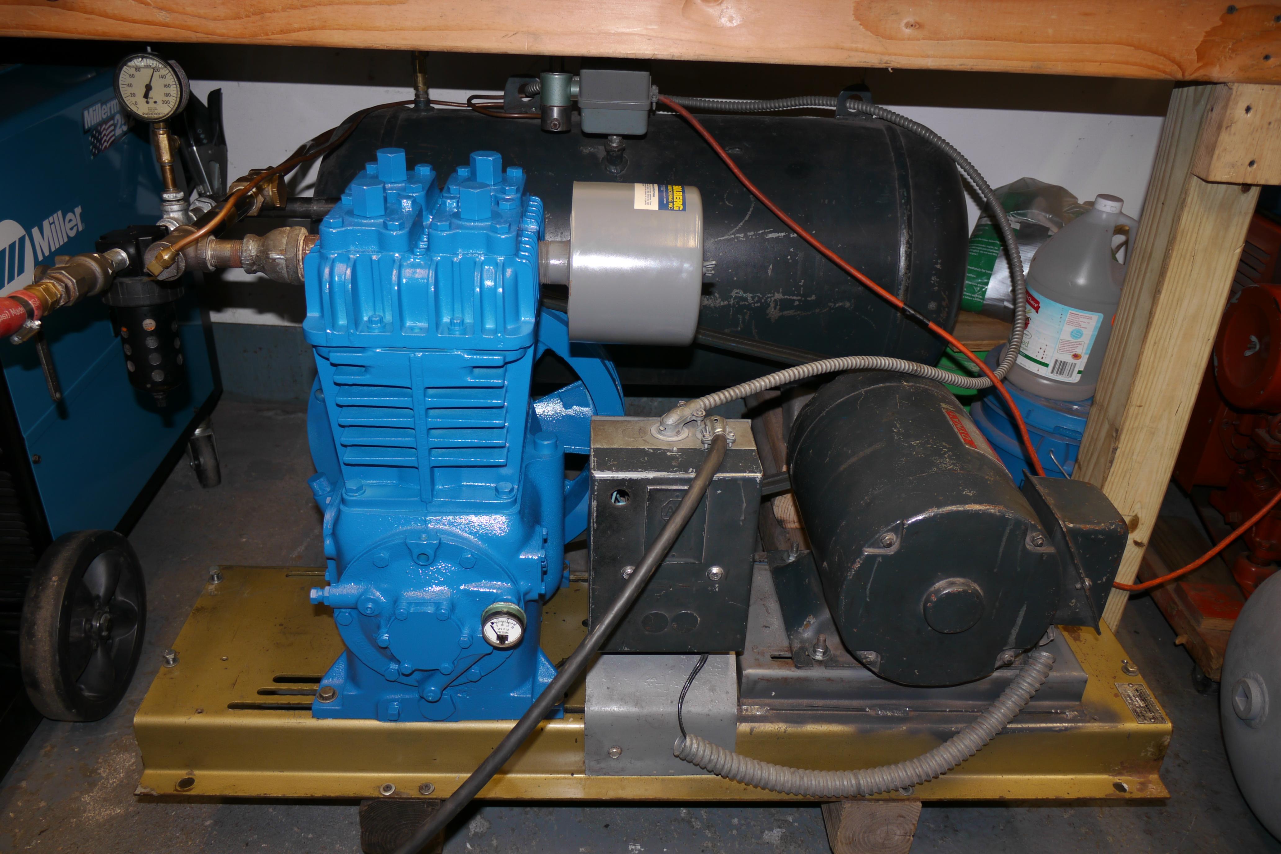
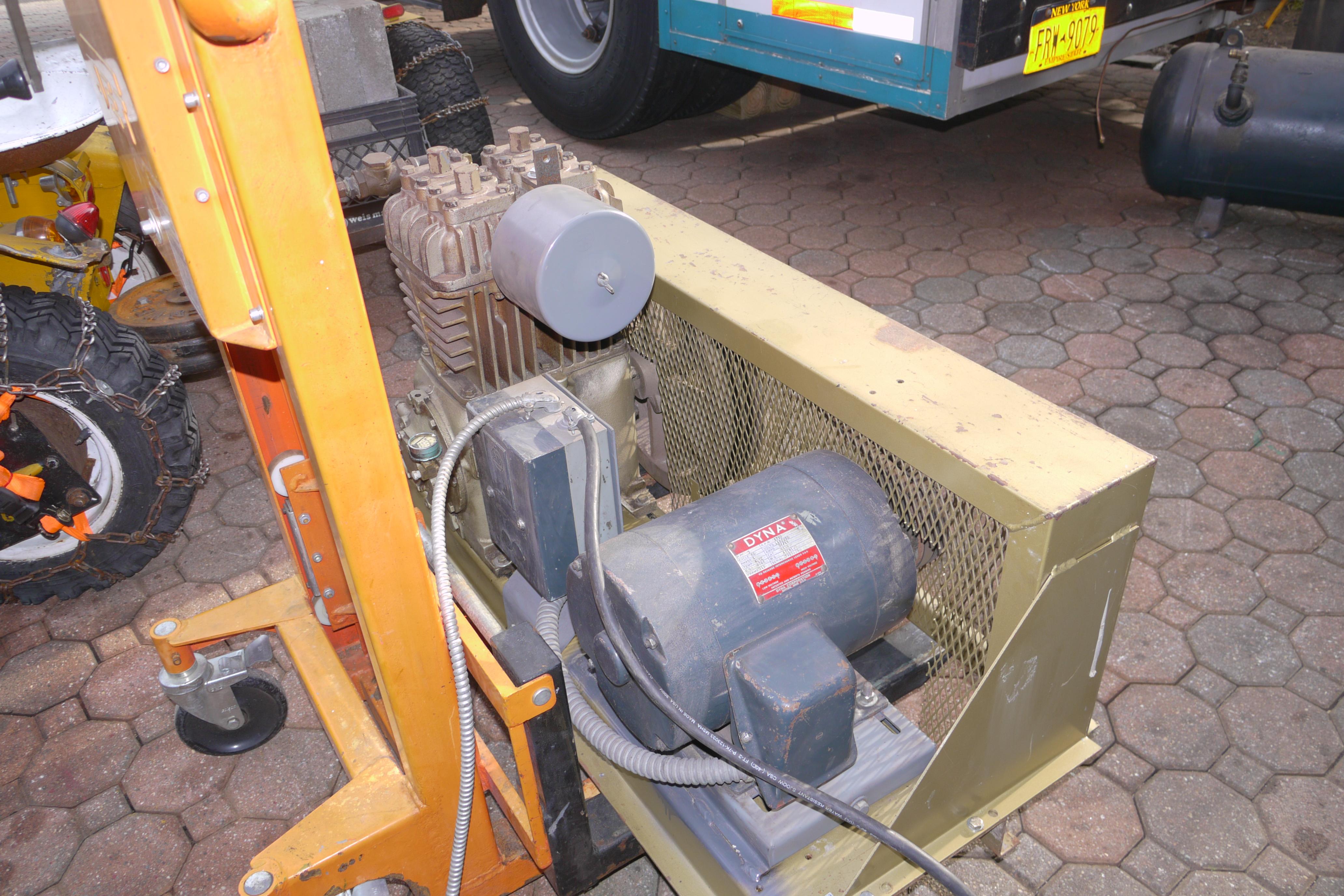
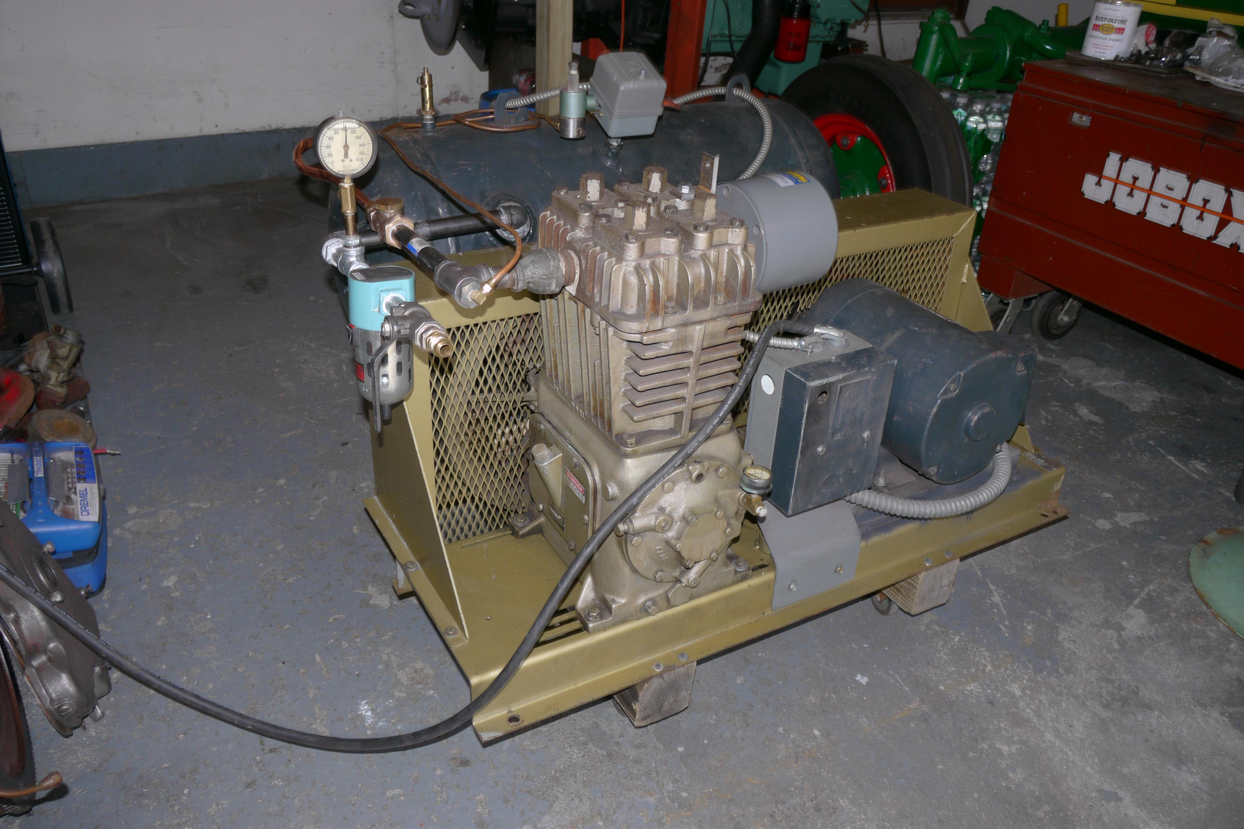
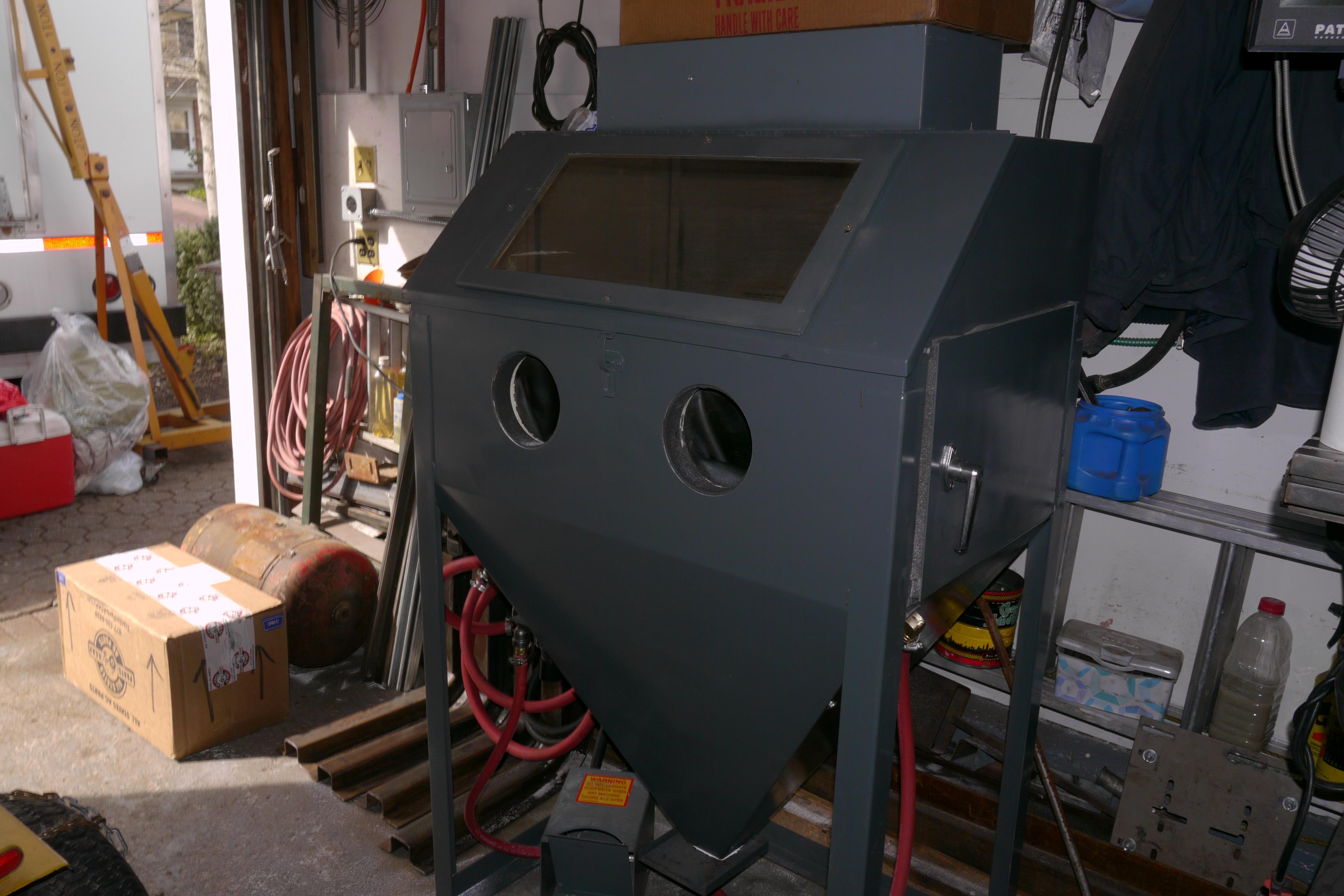
In April of 2015 I was in the market for a moderate sized industrial compressor to run my air tools, blow guns and my newly acquired Trinco blast cabinet. A friend of mine in Virginia led me onto this compressor as it was nearby and inexpensive. I was surprised to win the bid at just $180.00. The compressor was located about twenty miles away in Baldwin, New York. It came with a small 30 gallon air tank and a 3 horsepower 230 volt single phase Dyna motor. Arthur, the previous owner was able to power it up for me so that I could hear it work. Everything sounded normal despite the plumbing and wiring being an absolute mess. Arthur told me that this compressor powered the blast furnace of Merrick High School. When the 5 horsepower three phase motor that drove it burned out, the school discarded the compressor and he took the compressor head home. For this compressor to outlive a three phase motor is a testament to how overbuilt these Quincy compressors are. At this time I can only speculate that this compressor was mounted on a 60 or 80 gallon tank. I have never seen a model 230 compressor factory installed on a smaller tank. Arthur, like myself lives in suburbia and understands how valuable space is. His compressor outfit rolled right underneath his workbench, exactly how I planned to store and use my compressor. The workbench in my garage is narrow, so I needed to reorganize the components so that they would fit without obstruction.


Because Quincy no longer manufactures this specific model compressor today, it was rather difficult to find information and specifications on it. The compressor model number “230” happens to be a common number for electrical voltage “230 Volts” so all of my searches ended up with hundreds of different 230 volt compressors. After perusing Quincy’s current QR-25 lineup I noticed that the model 240 compressor was strikingly similar in design and appearance to my model 230 compressor. It turns out that the only major difference between the 230 and the 240 compressors is the bore of the pistons. My model 230 compressor has a 3-1/2″ bore and 3″ stroke, whereas the slightly larger and current model 240 has a 4″ bore and a 3″ stroke. Luckily the current QR-25 brochure listed the cfm output of the 240 compressor as well as a suggested motor size and rpm range. Knowing that a model 240 compressor can produce 23.5 cfm (cubic feet per minute) of air flow at 100psi at its maximum speed of 900rpm, I made an educated guess that my 230 compressor was able to produce right around 20 cfm of air volume at 100psi. 100 psi, (pounds per square inch) is the limit and rating of Quincy’s entire line of single stage compressors. When higher air pressure is required, a two stage compressor must be used.

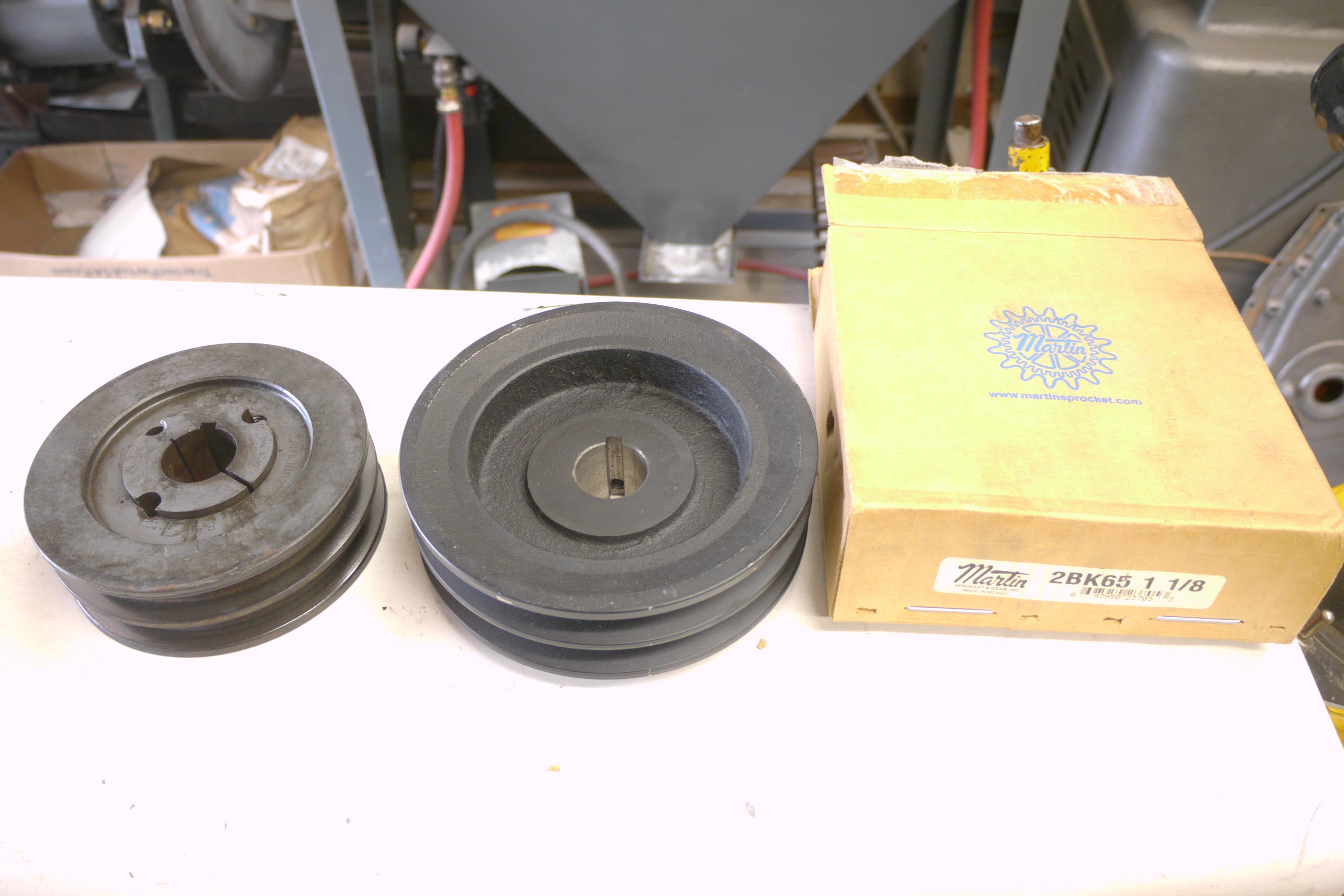
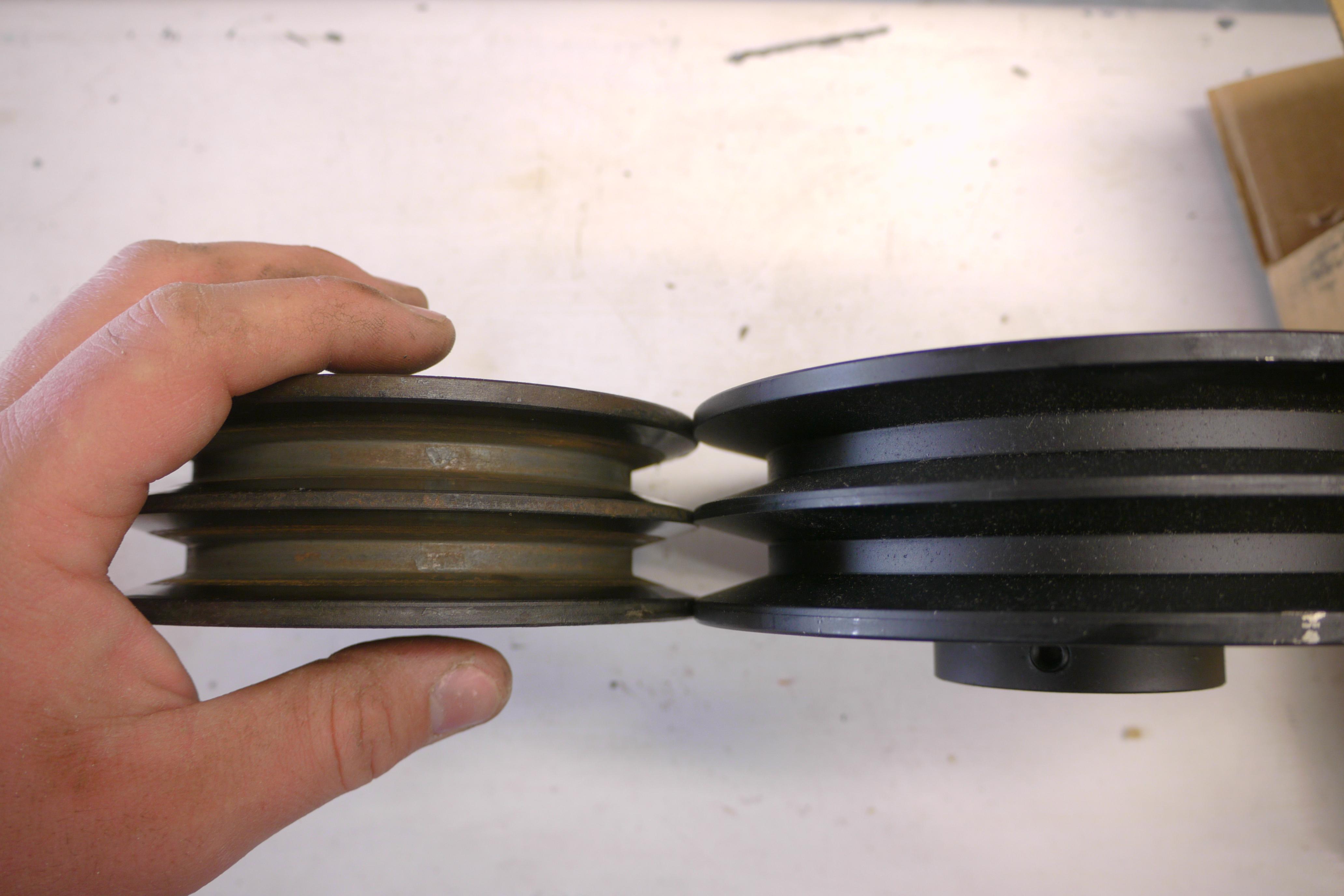
One of the first things I noted was the relatively slow charge time of the 30 gallon compressor tank. I determined that the compressor was spinning well below its rated speed. The 3 horsepower motor was turning the compressor at just 565rpm. This resulted in a net volume output of just 10.8 cfm. I measured the current draw of the motor and checked it against the nameplate rating of the motor. The motor was drawing 18.6 amps at 100psi, just over the rating of the motor. I traced the high amperage motor draw to three things, thick old oil in the compressor, misaligned belts, and wires incapable of supporting a motor of this size. I was able to get the running amperage of the motor to be 14.2 amps, well underneath the 18 amp rating of the motor. I purchased a larger diameter pulley for the motor (6-1/4″ instead of 5-1/8″) which bumped the speed of the compressor up to 680rpm and output to 14.3cfm. The increased compressor speed increased the load on the motor to 16.2 amps, just under the 18 amp rating of the motor.
14.3cfm might not sound like much, but it is a pretty sizeable amount of air volume, considering the biggest reciprocating compressors that you can buy at a big box store are only about 6cfm. Unfortunately 14cfm isnt quite enough air to sandblast efficiently. My Trinco bead blast cabinet requires 20cfm of air volume with the smallest 3/16″ blast nozzle installed. My compressor simply could not keep up. I had to continually let off of the blast pedal to keep the compressor operating in the 90-100psi range. 90psi is considered the most efficient pressure for media blasting.
Design Decisions
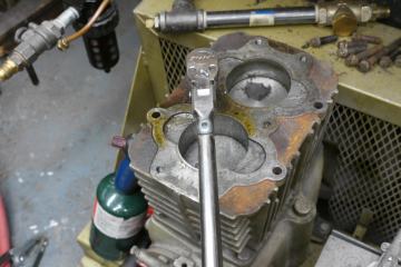
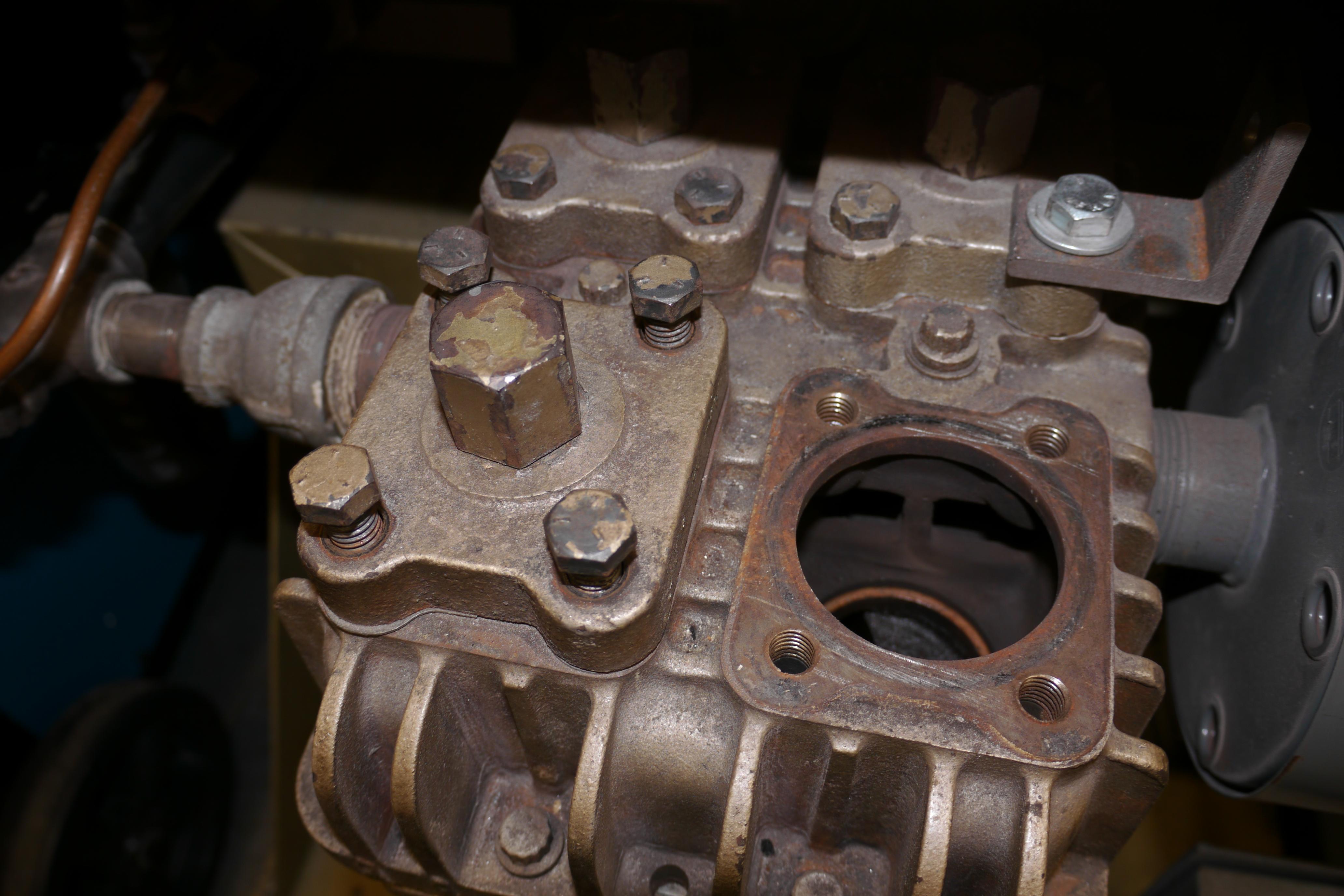
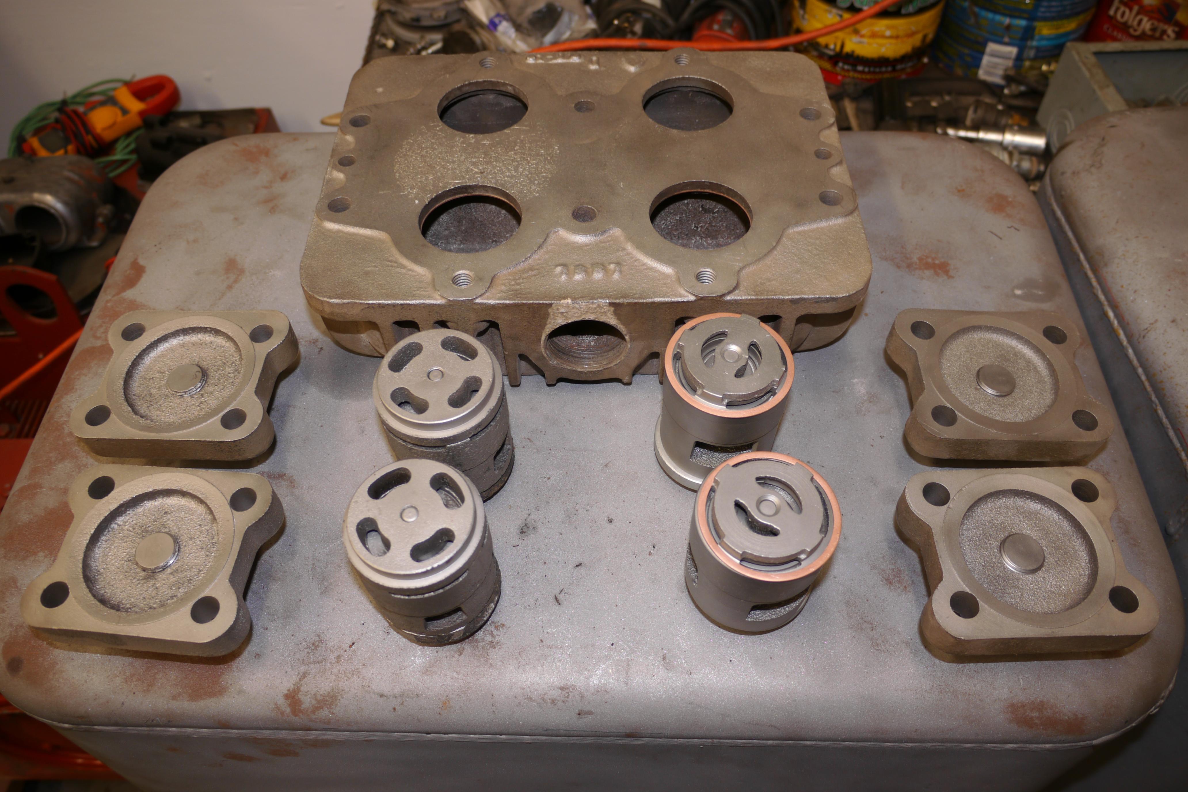
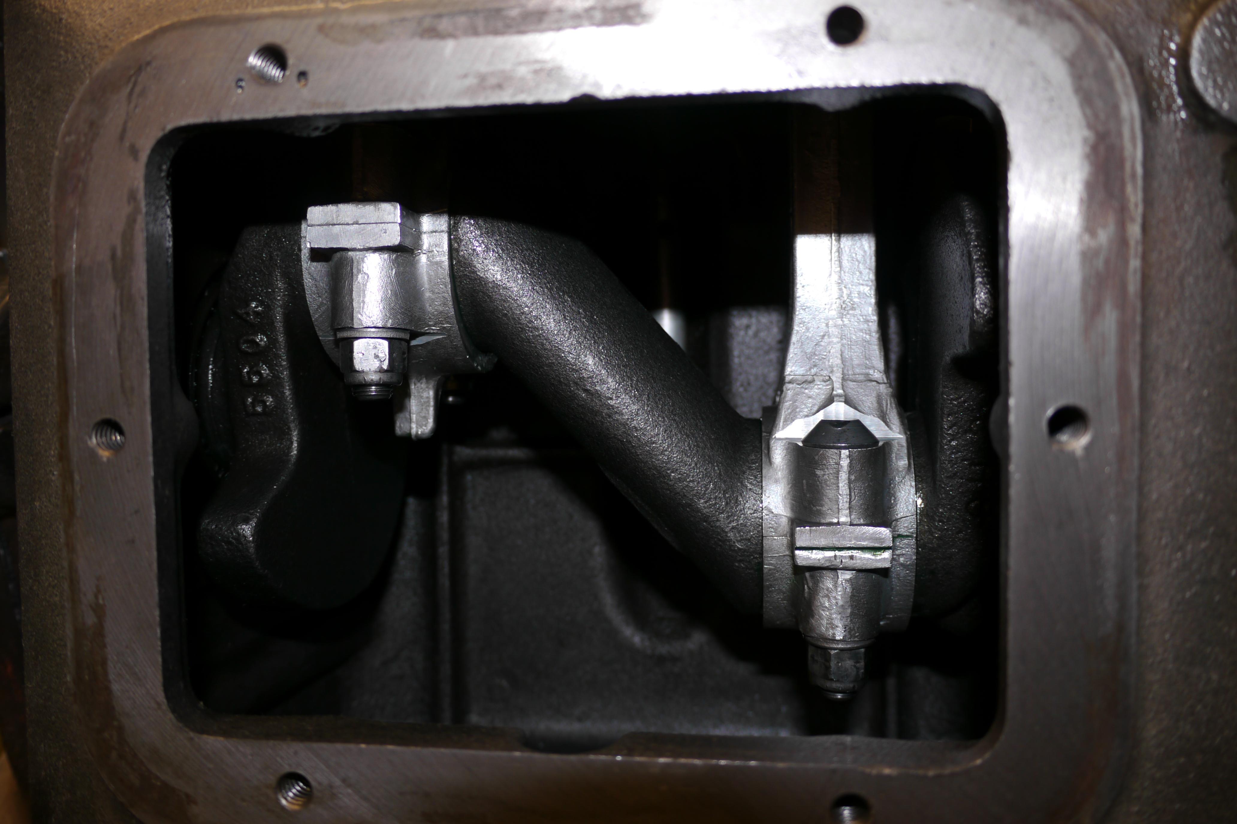
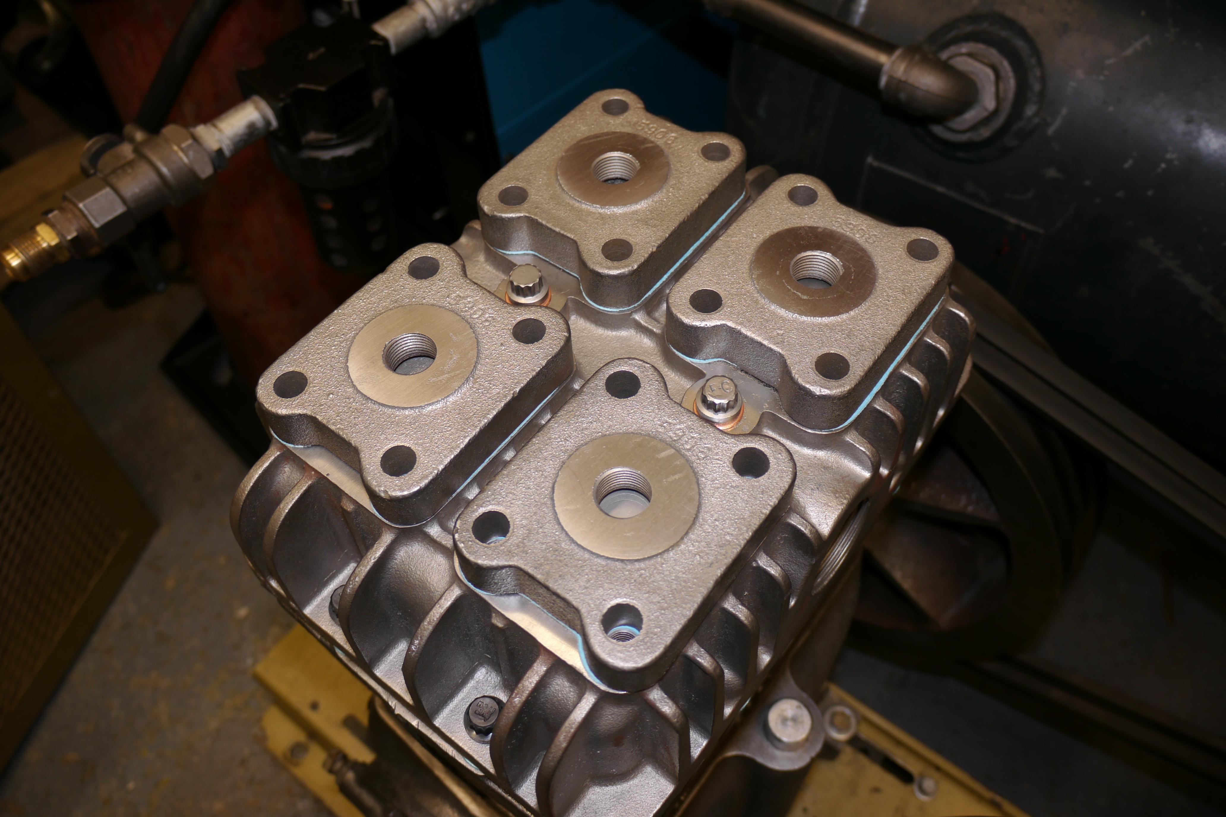
Unfortunately on June 16th of 2015 my Quincy model 230 compressor developed a ticking sound. With a hundred projects already on my plate I decided to pull the valve covers and take a look inside the compressor. I removed the intake valve cover off of the rear cylinder, and everything looked great inside. The valve spacer was in great shape, and the intake valve looked like it was in decent shape.

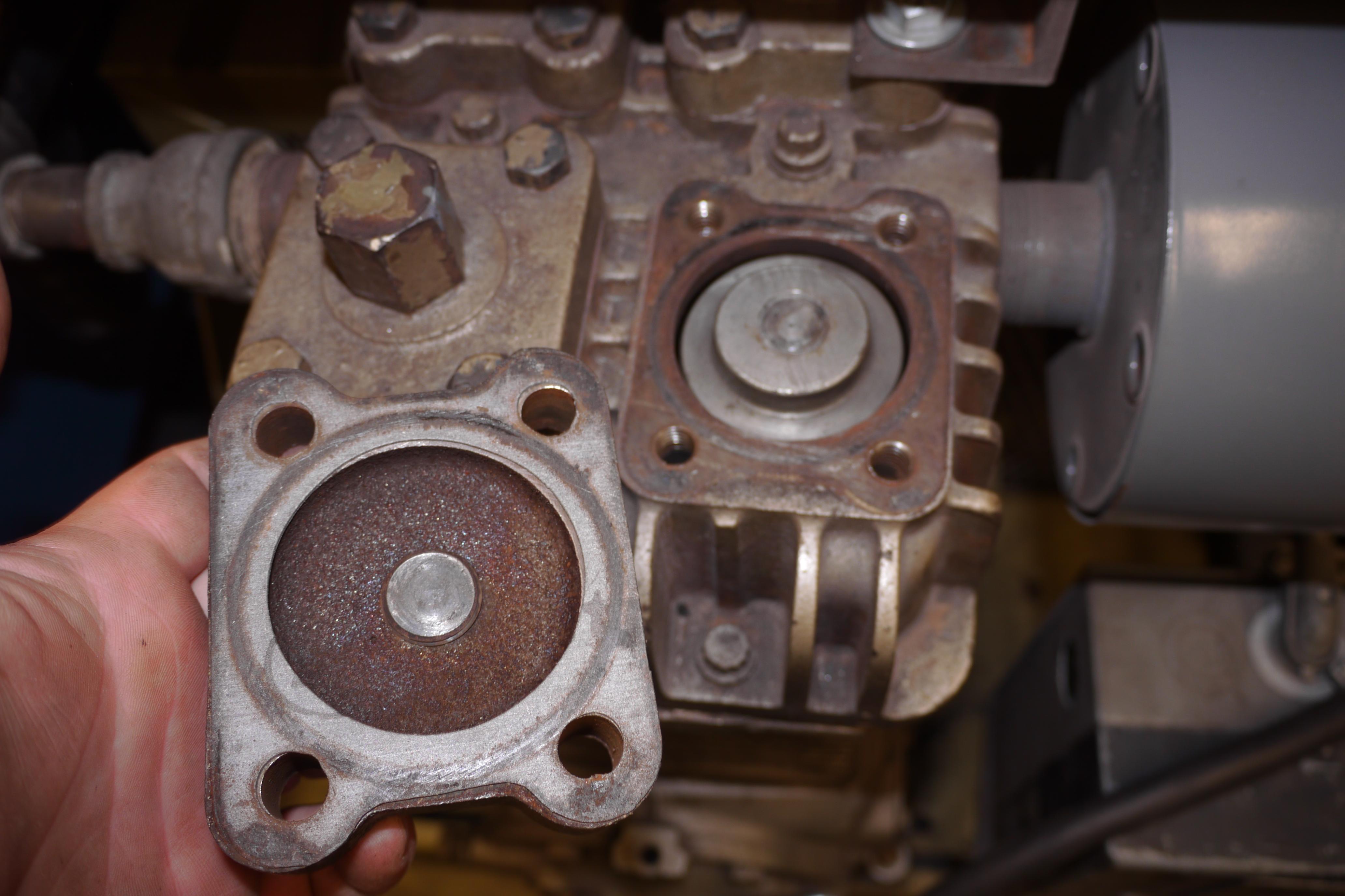
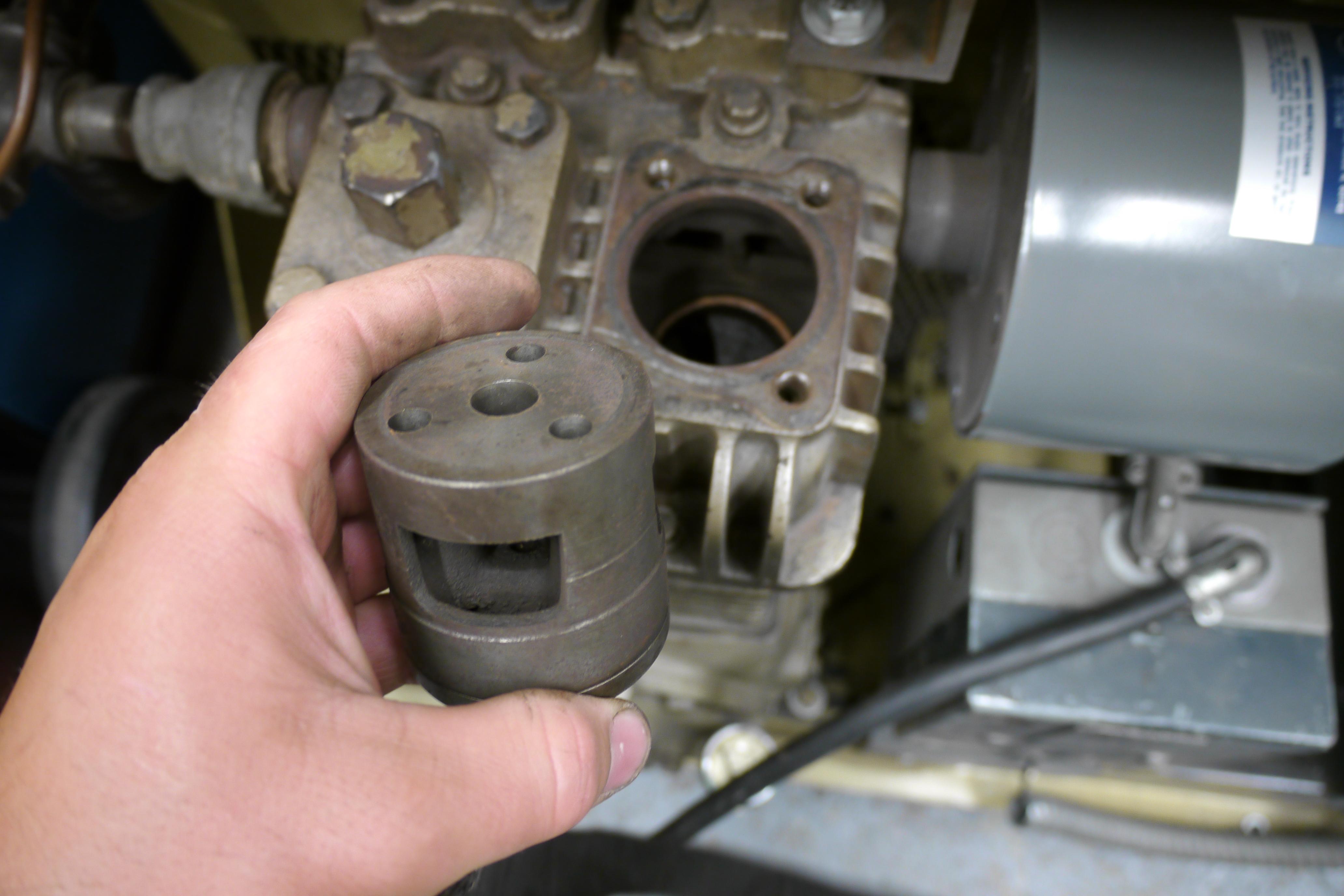
Not seeing anything out of the ordinary, I removed the discharge valve cover for the rear cylinder. Yikes look at all of that rust and scale! I grabbed the shop-vac and started sucking up all of the loose scale. It took quite a lot of wiggling to get the discharge valve body out of the cylinder head. The entire valve was rusted top to bottom, it is truly amazing that it still worked.

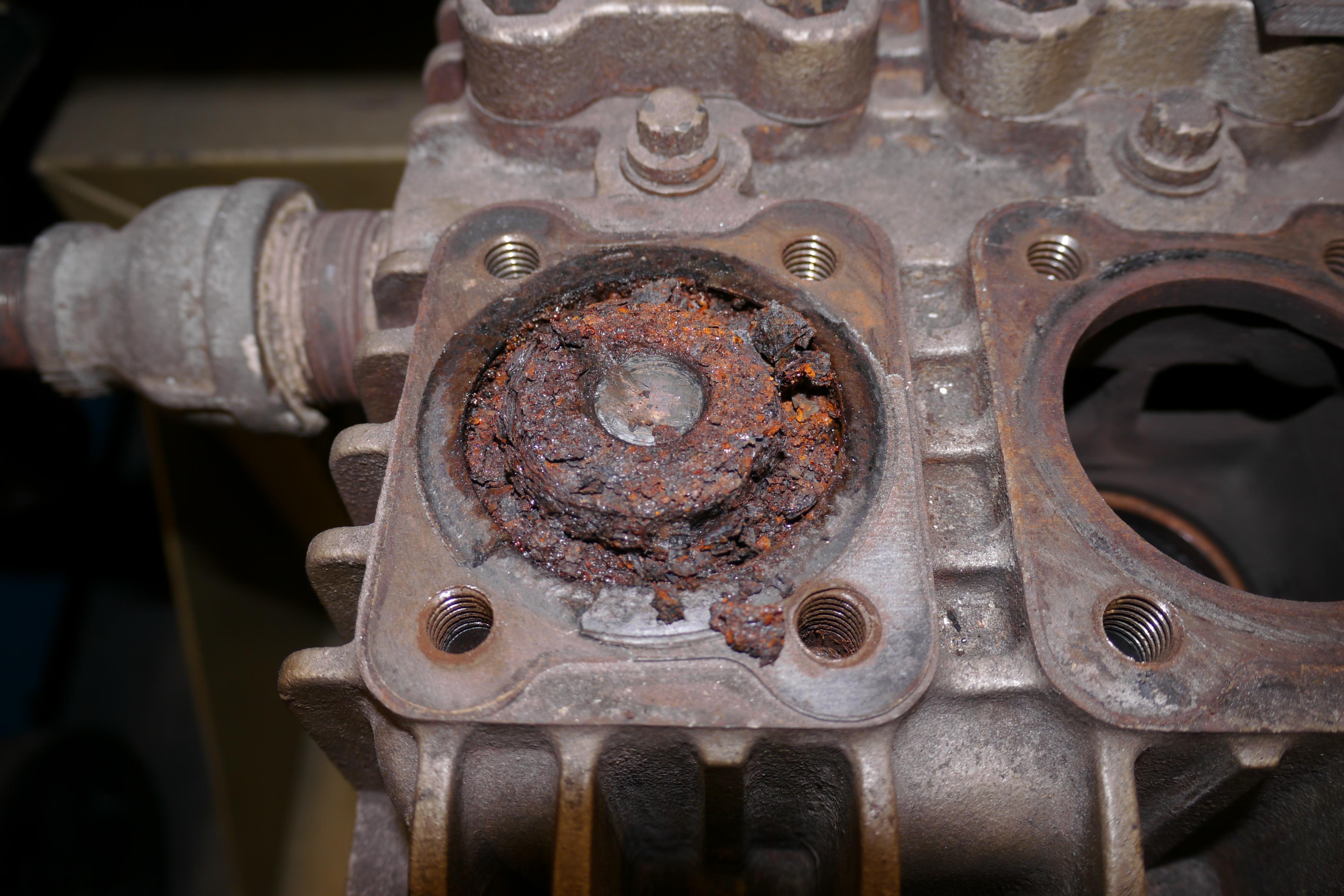
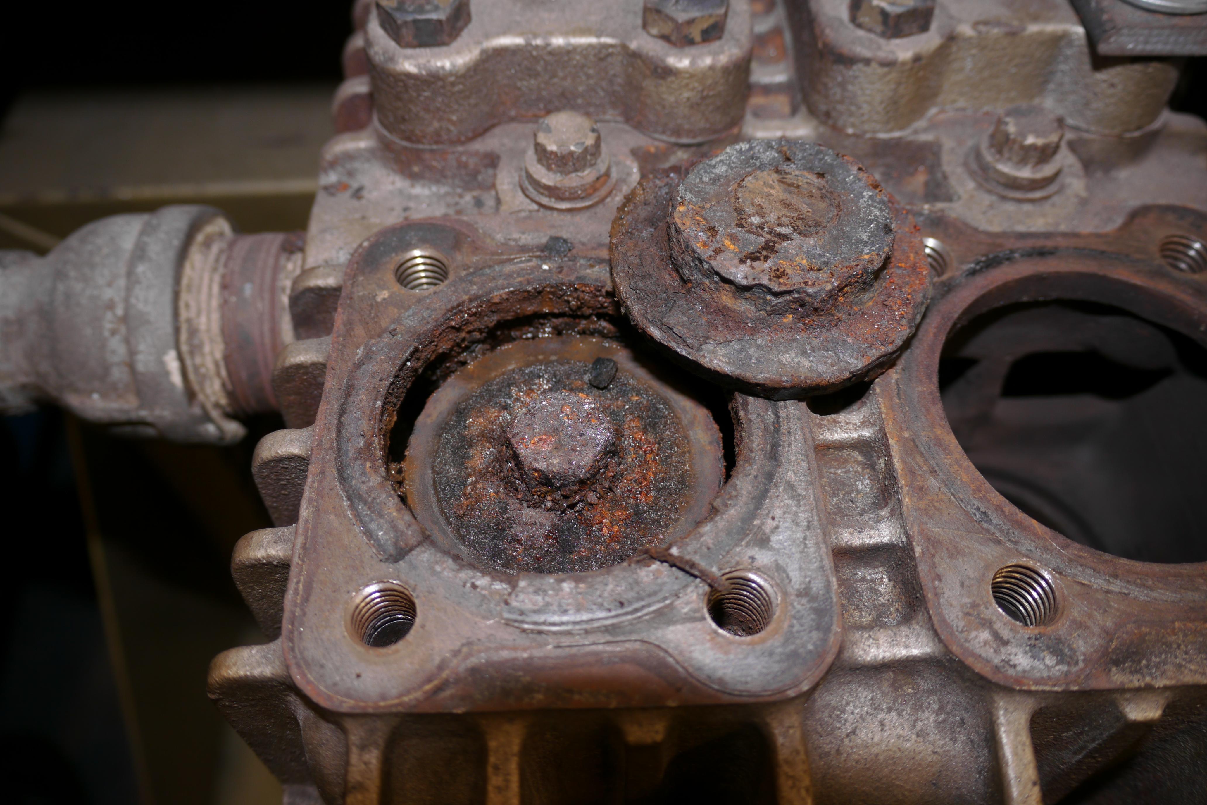
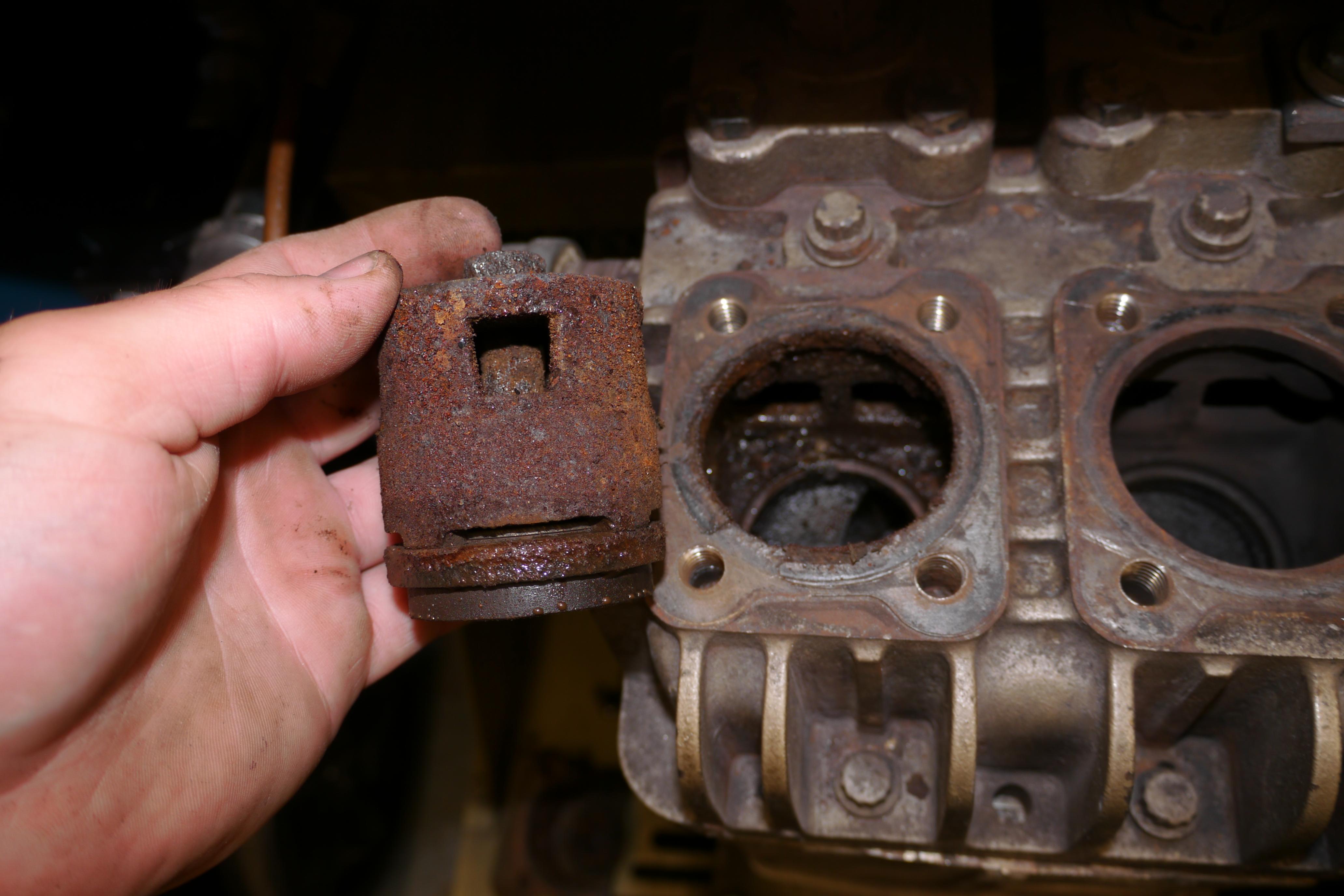
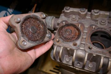
Seeing the condition of the rear two valves, I decided to pull the front valve covers, spacers and valves from the cylinder head. Like the rear cylinder, the front cylinder had a moderately clean intake valve and an extremely rusty discharge valve.
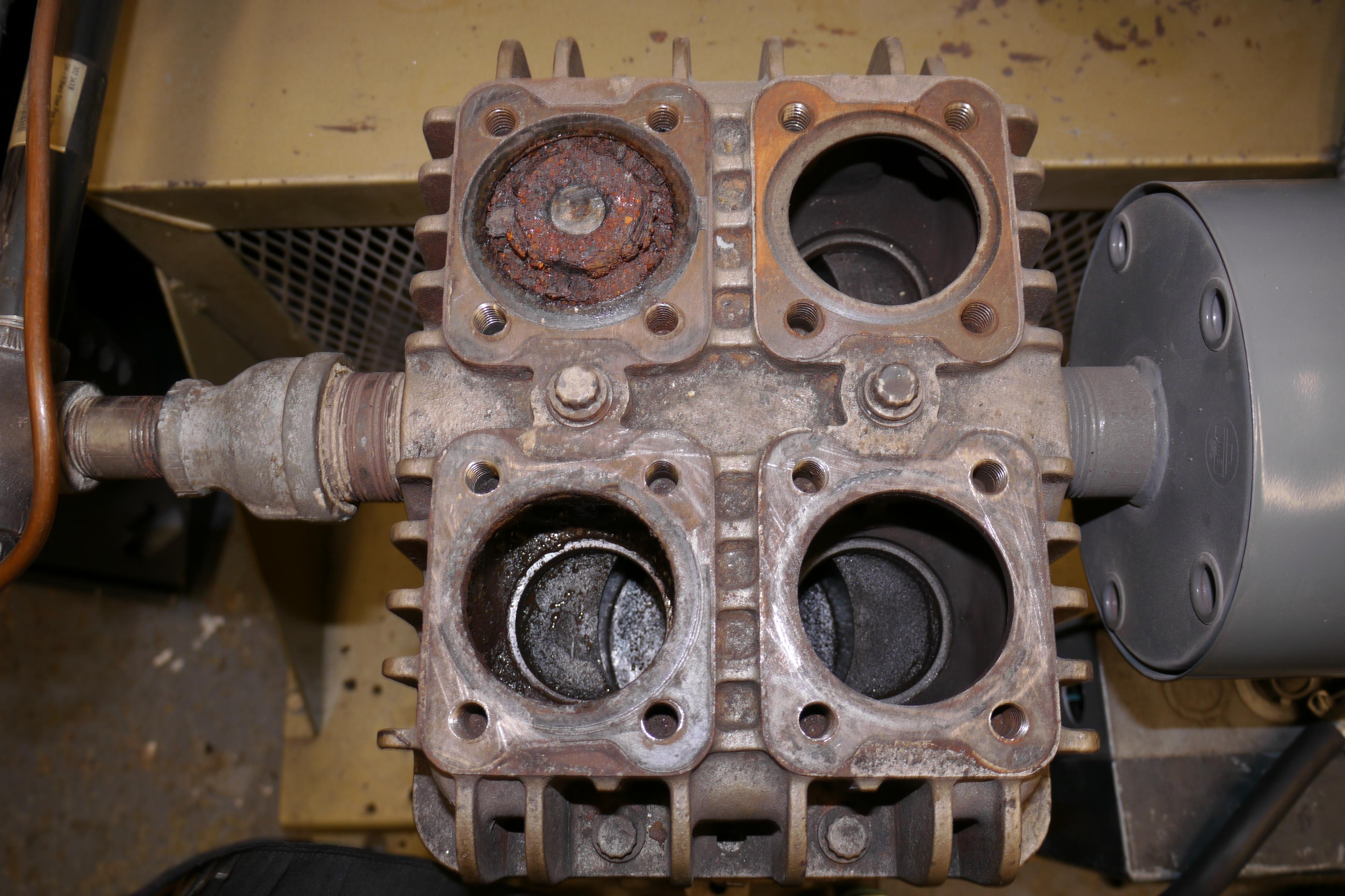


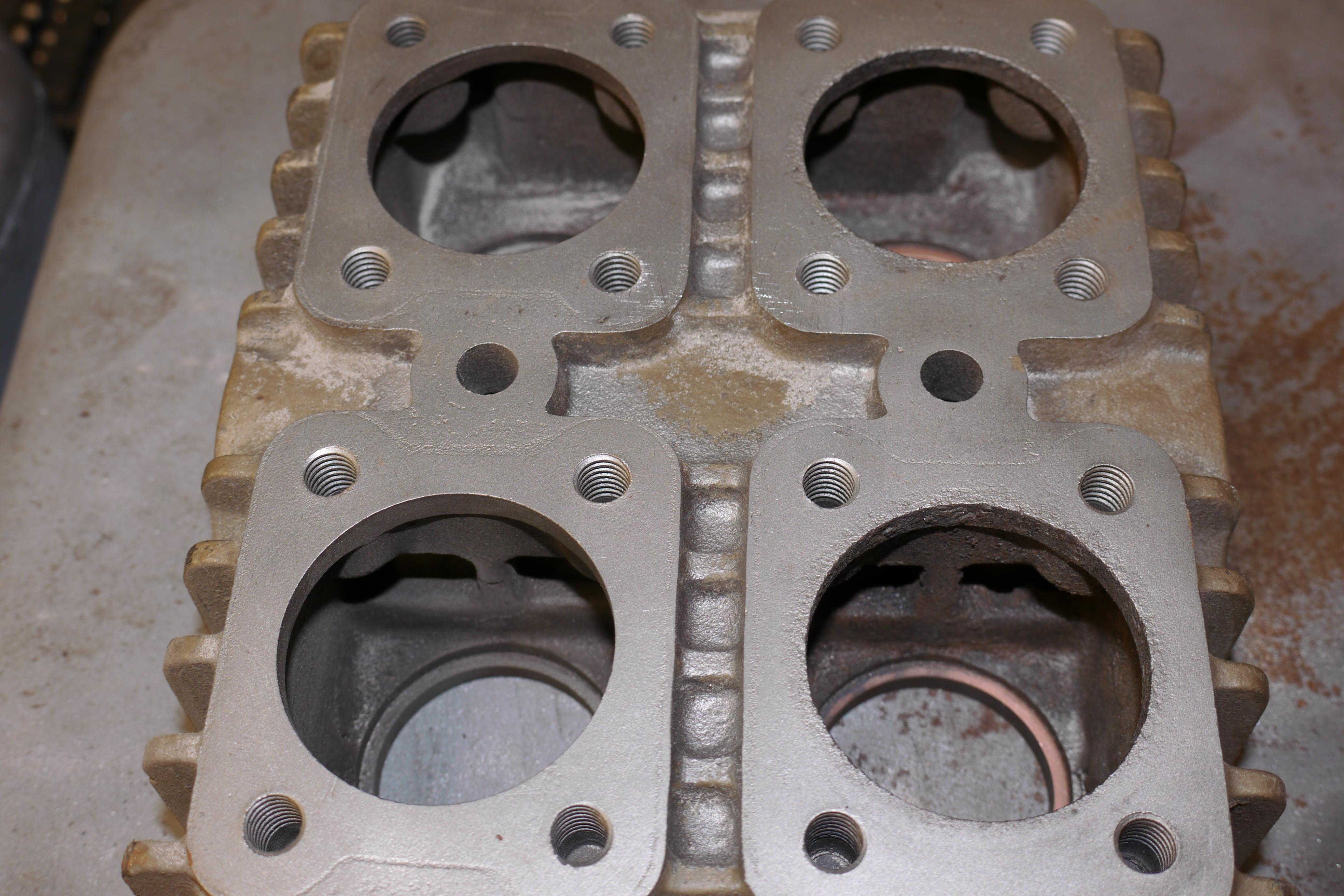
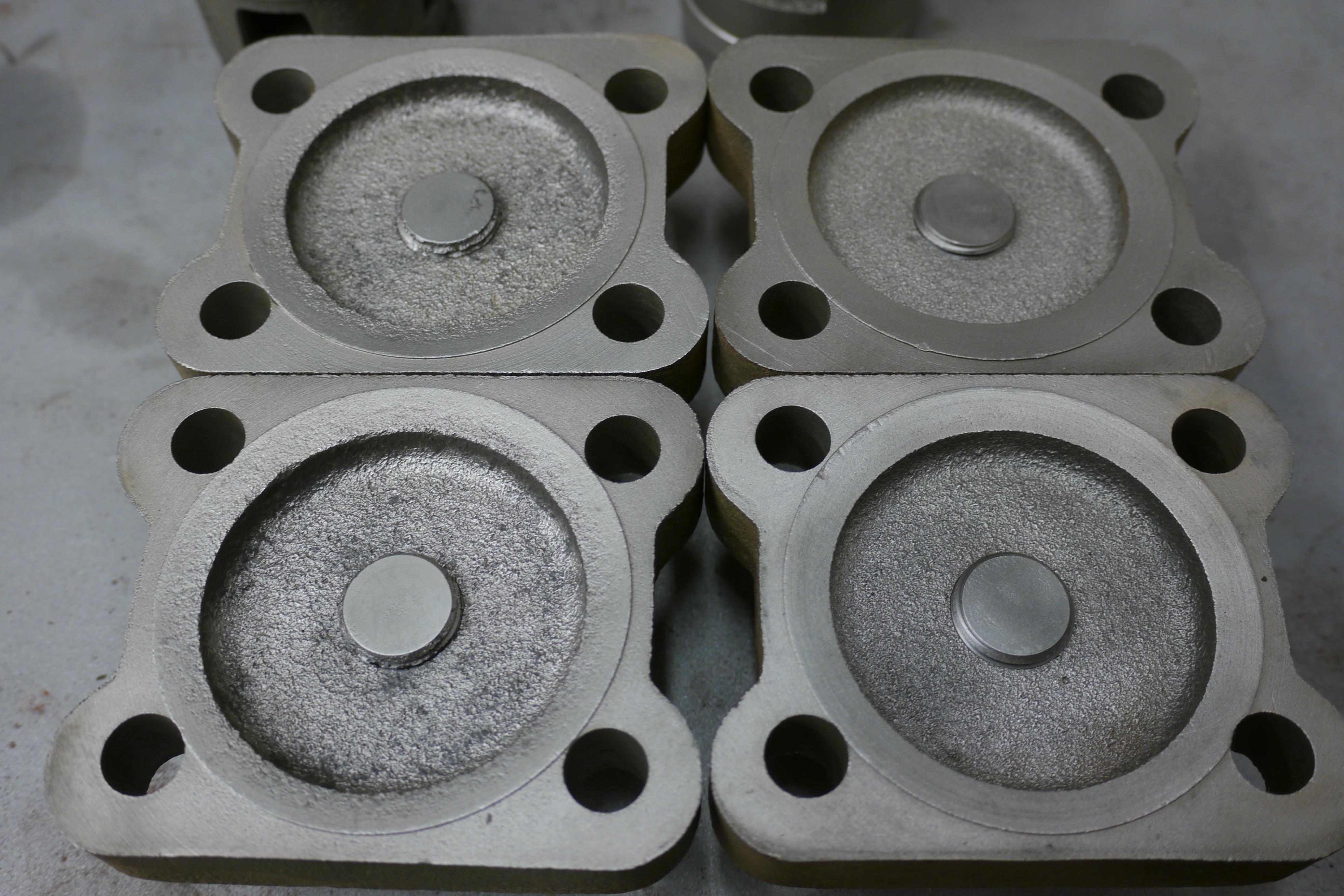
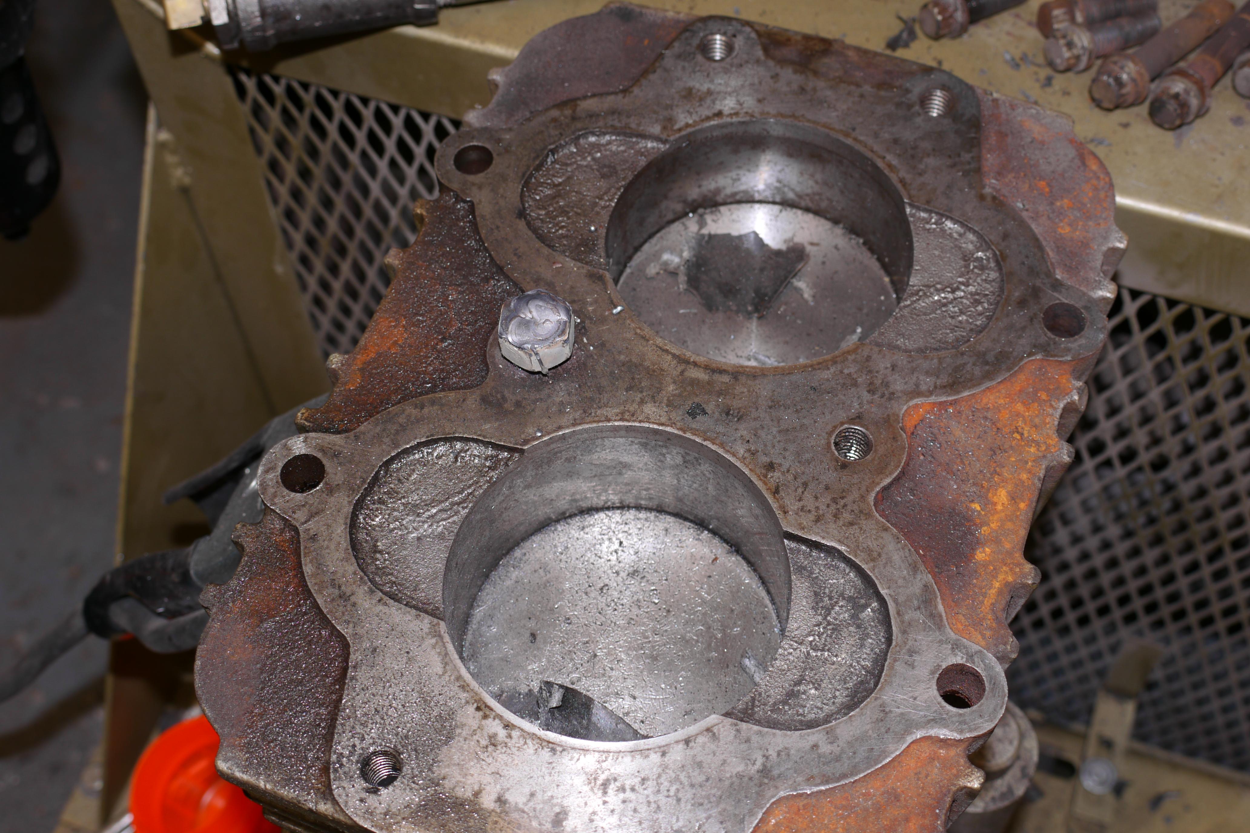
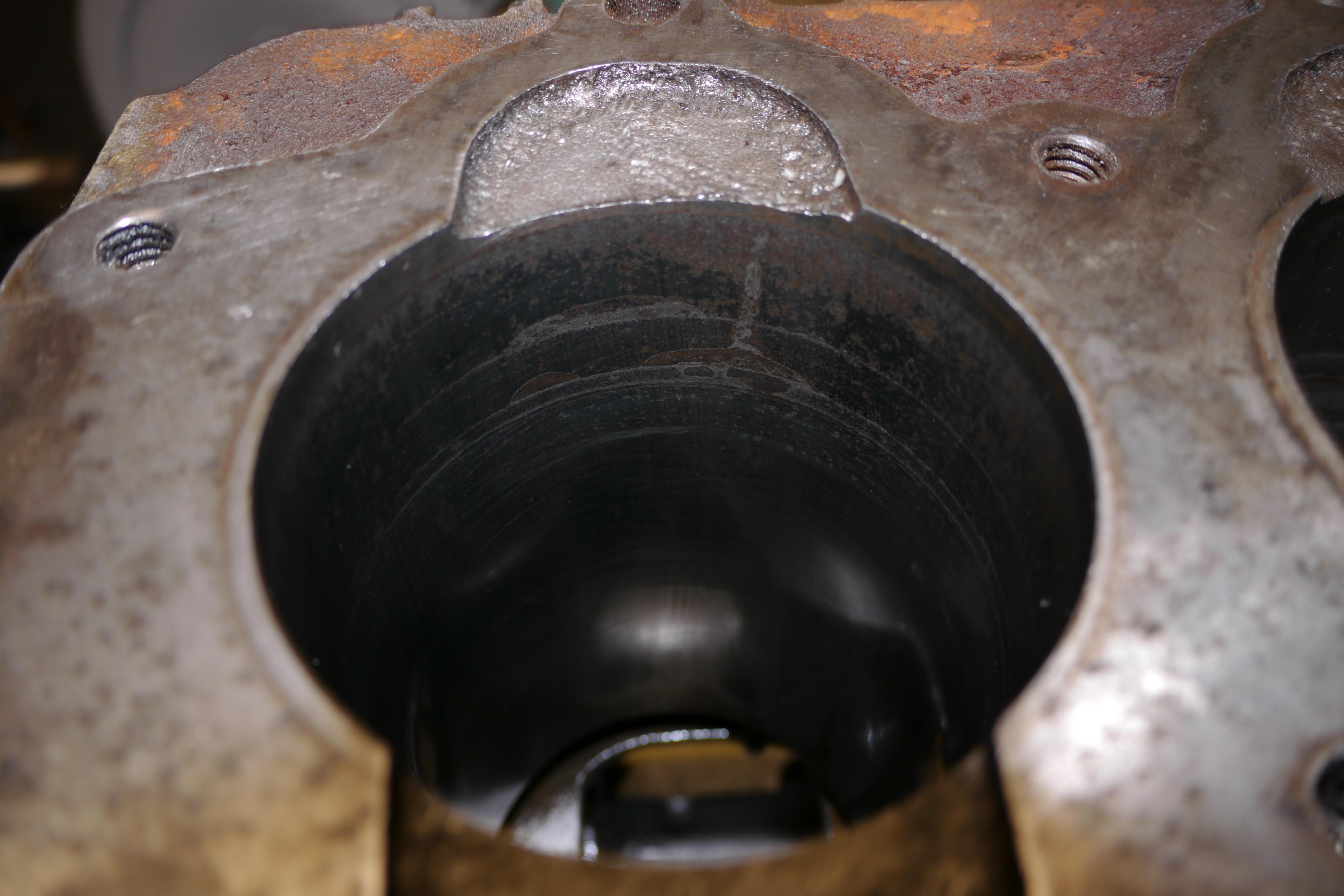
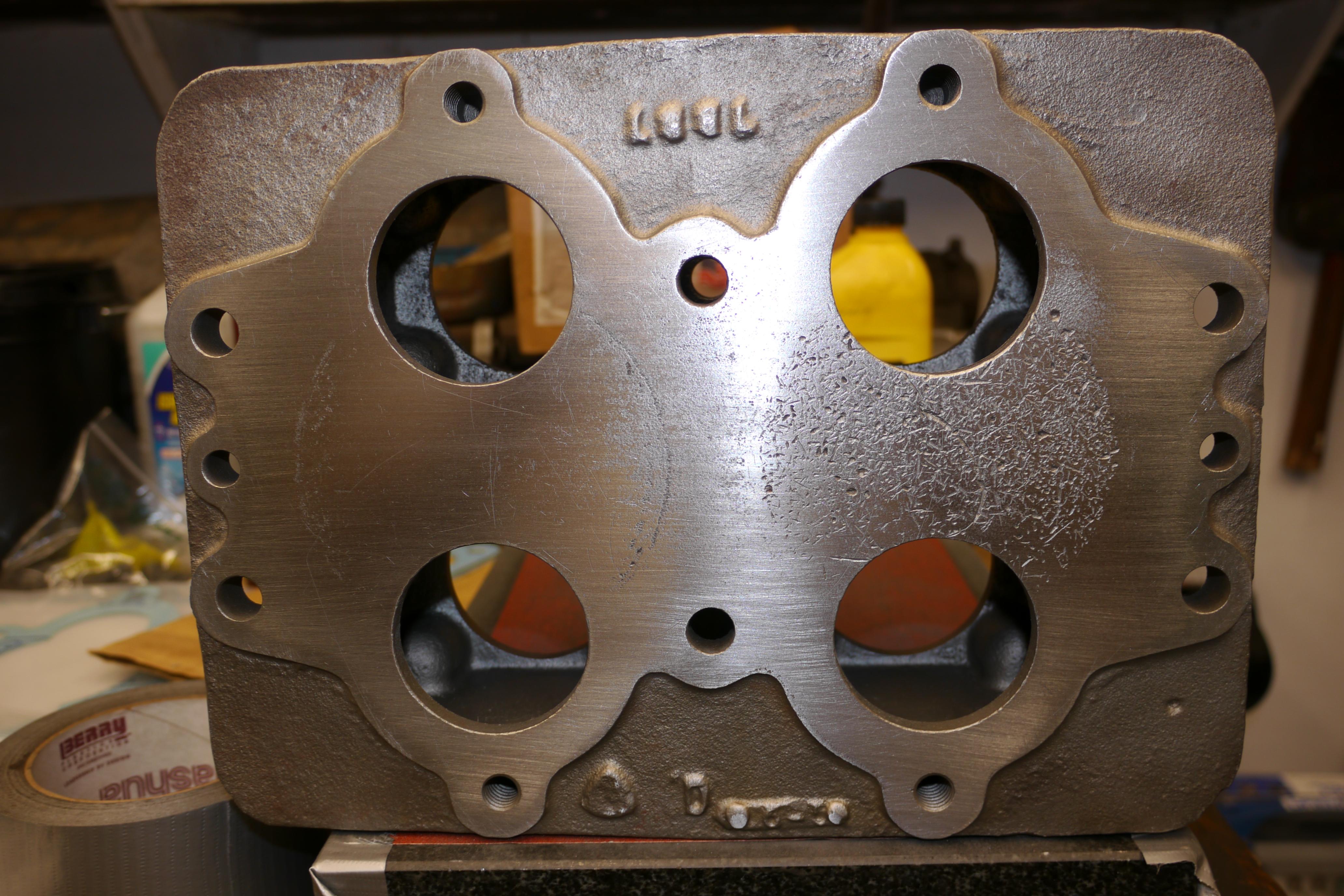
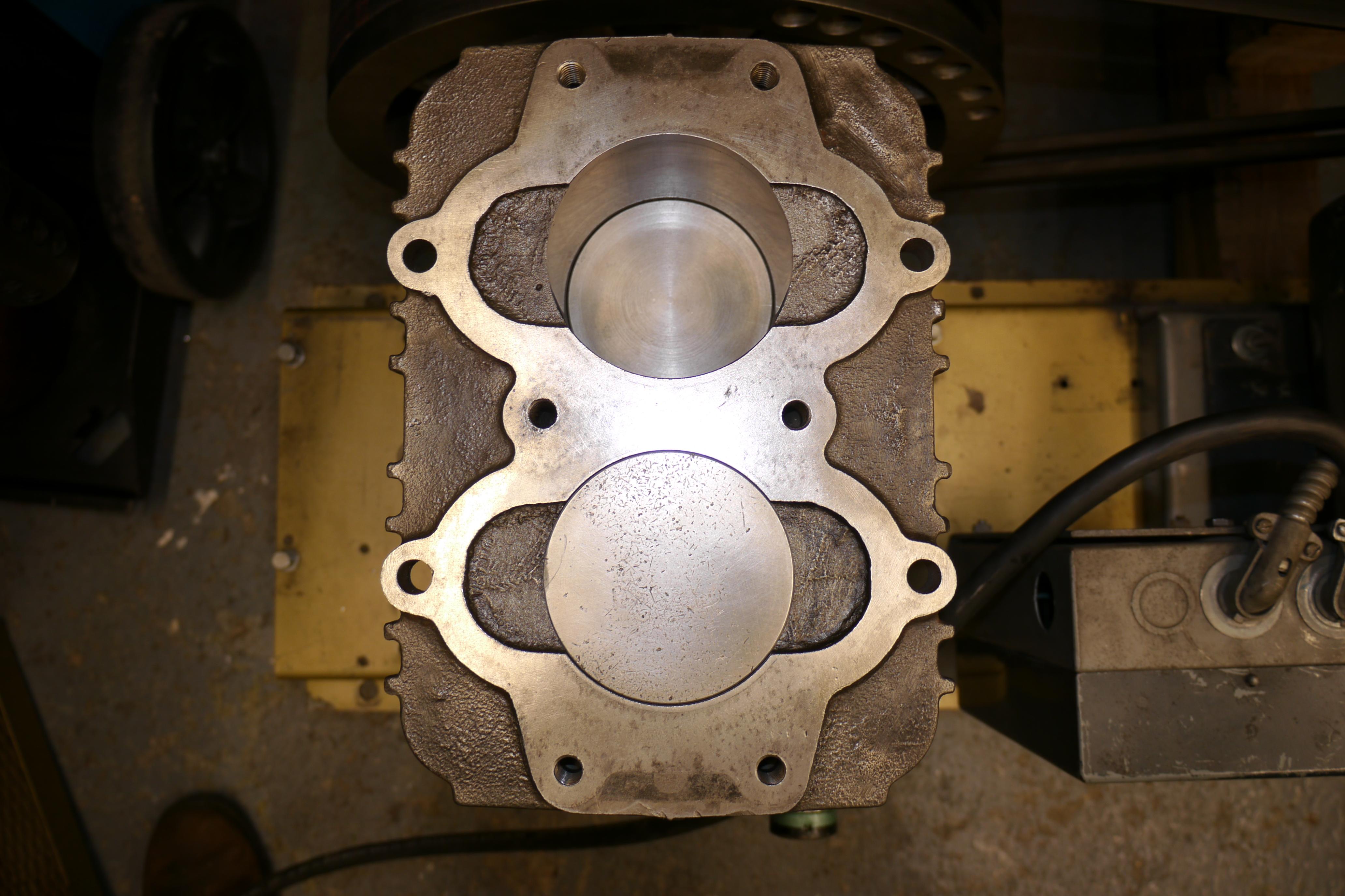
It is absolutely amazing that this compressor compressed air at all with the discharge valves in such poor condition. The cylinder head was literally a mess, full of rust and loose scale. Even though I vacuumed up as much loose scale as I could find, the cylinders received their fare share of rust from the cylinder head above. I removed the air cleaner and the discharge line from the cylinder head, and proceeded to remove the cylinder head. Of course one of the cylinder head bolts sheared off. Needless to say I was able to remove the cylinder head without too much trouble. Upon removing the cylinder head my first thought was: “Wow look at how rusty those cylinders are” and then “Oh boy this is going to be expensive."
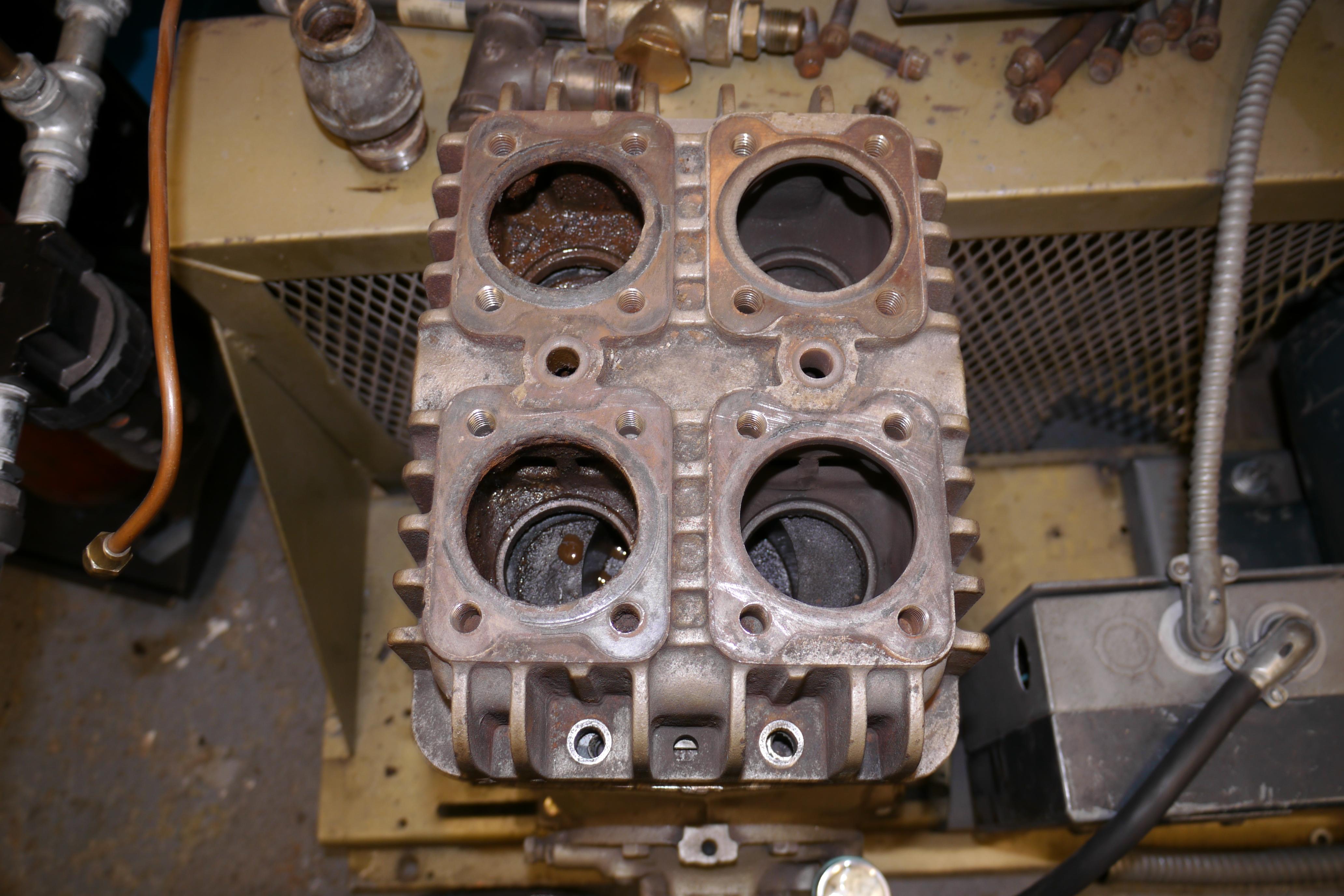
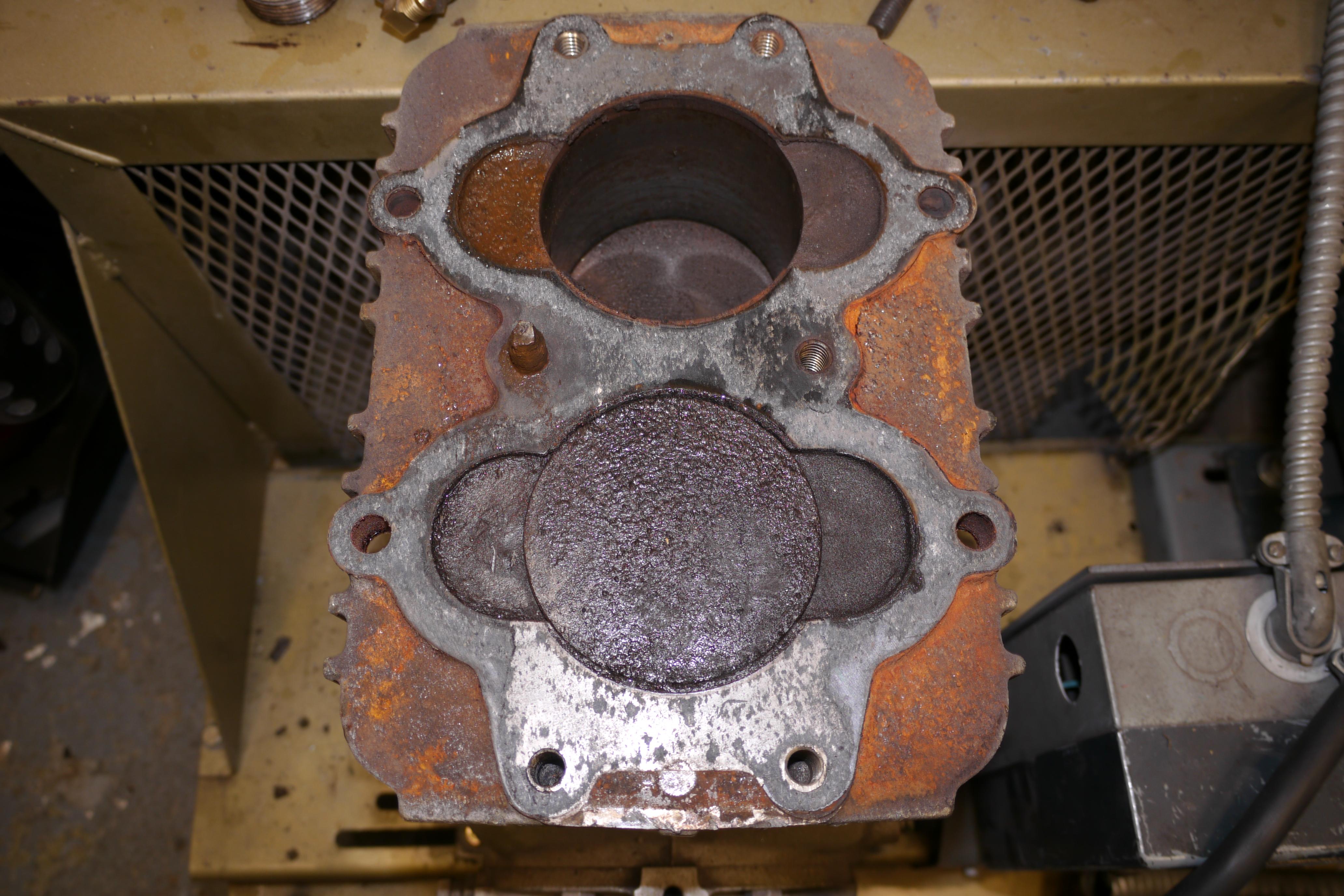
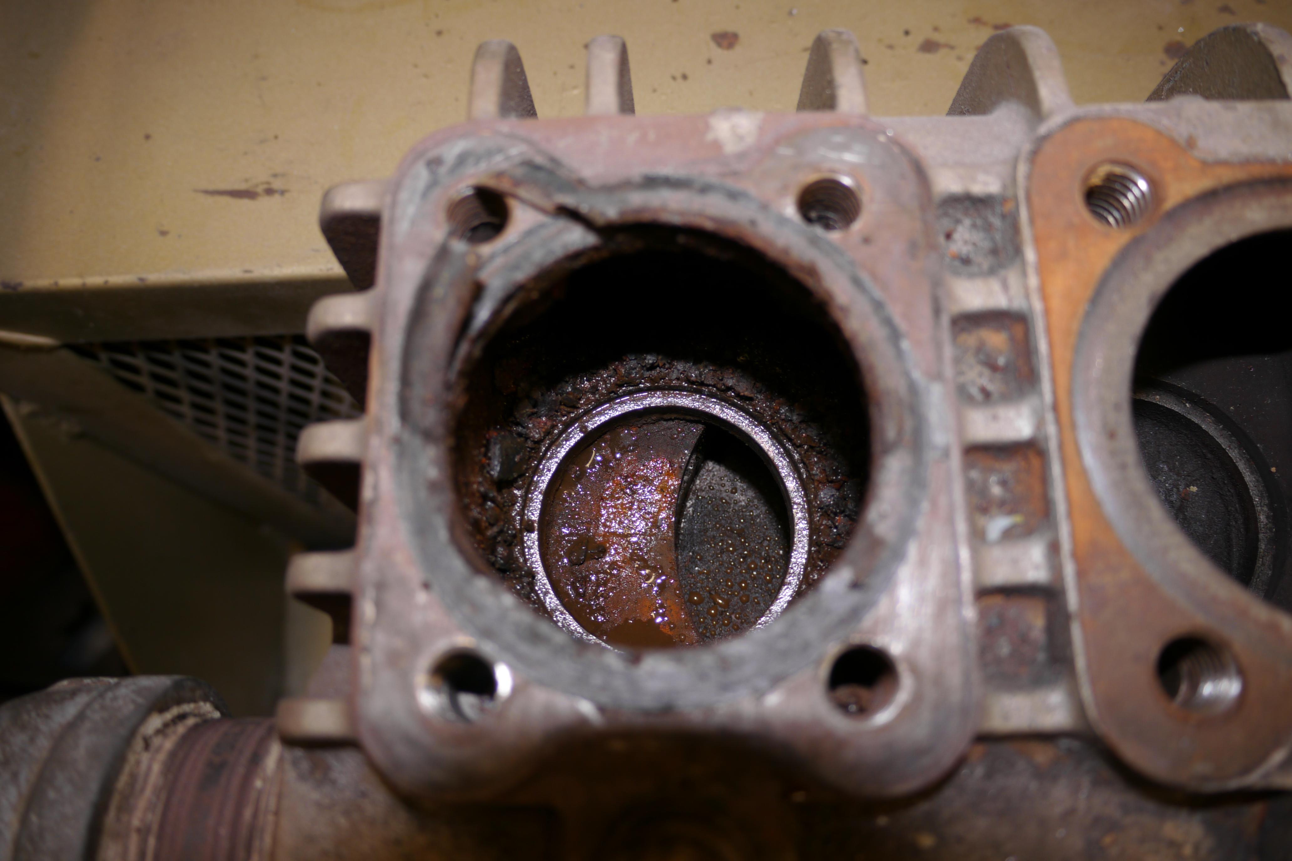
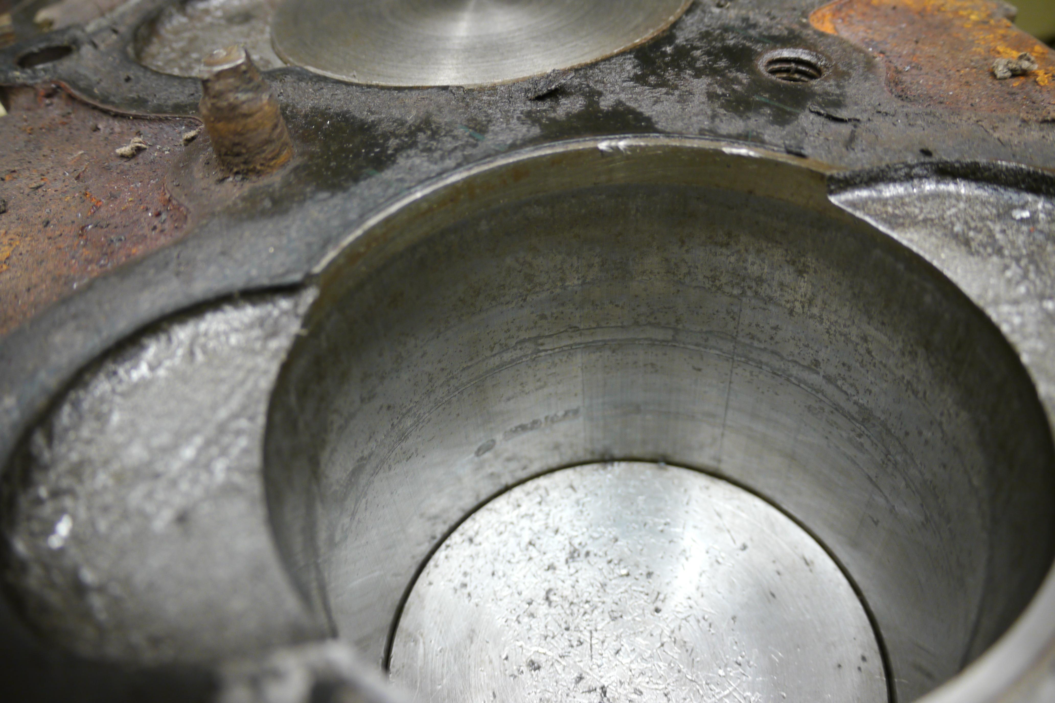
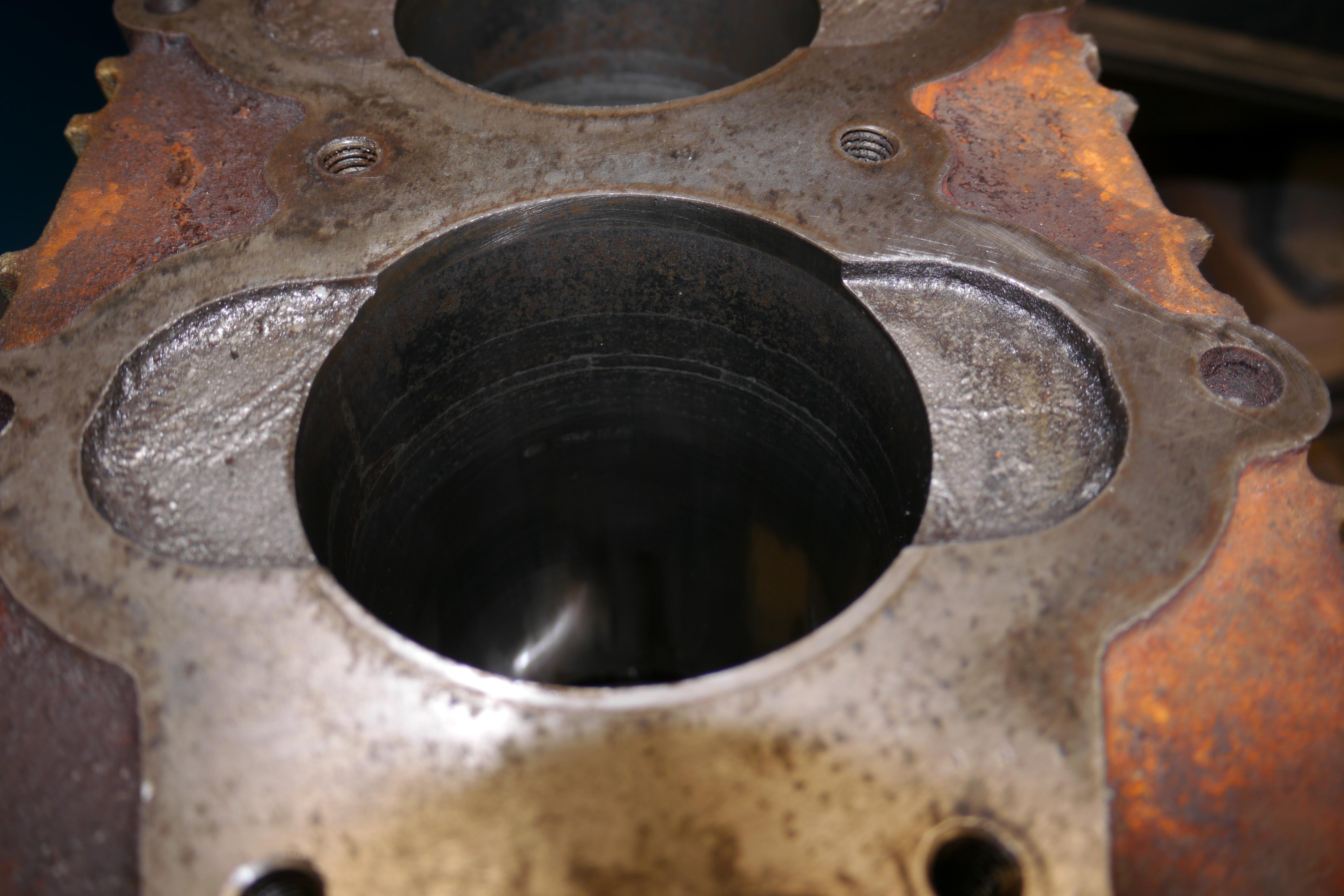
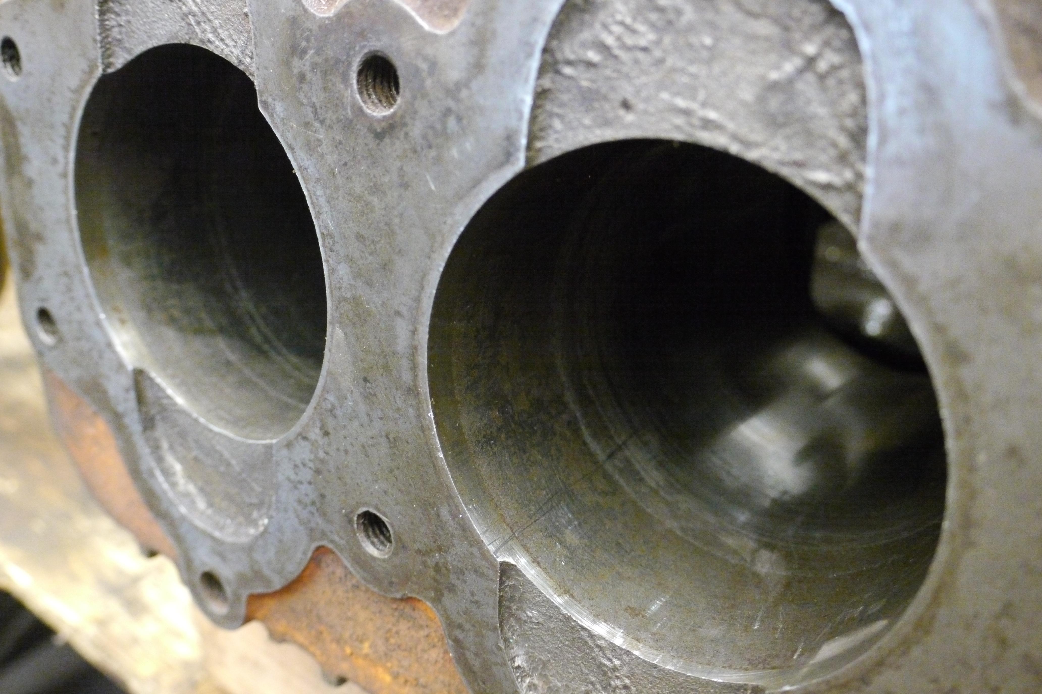
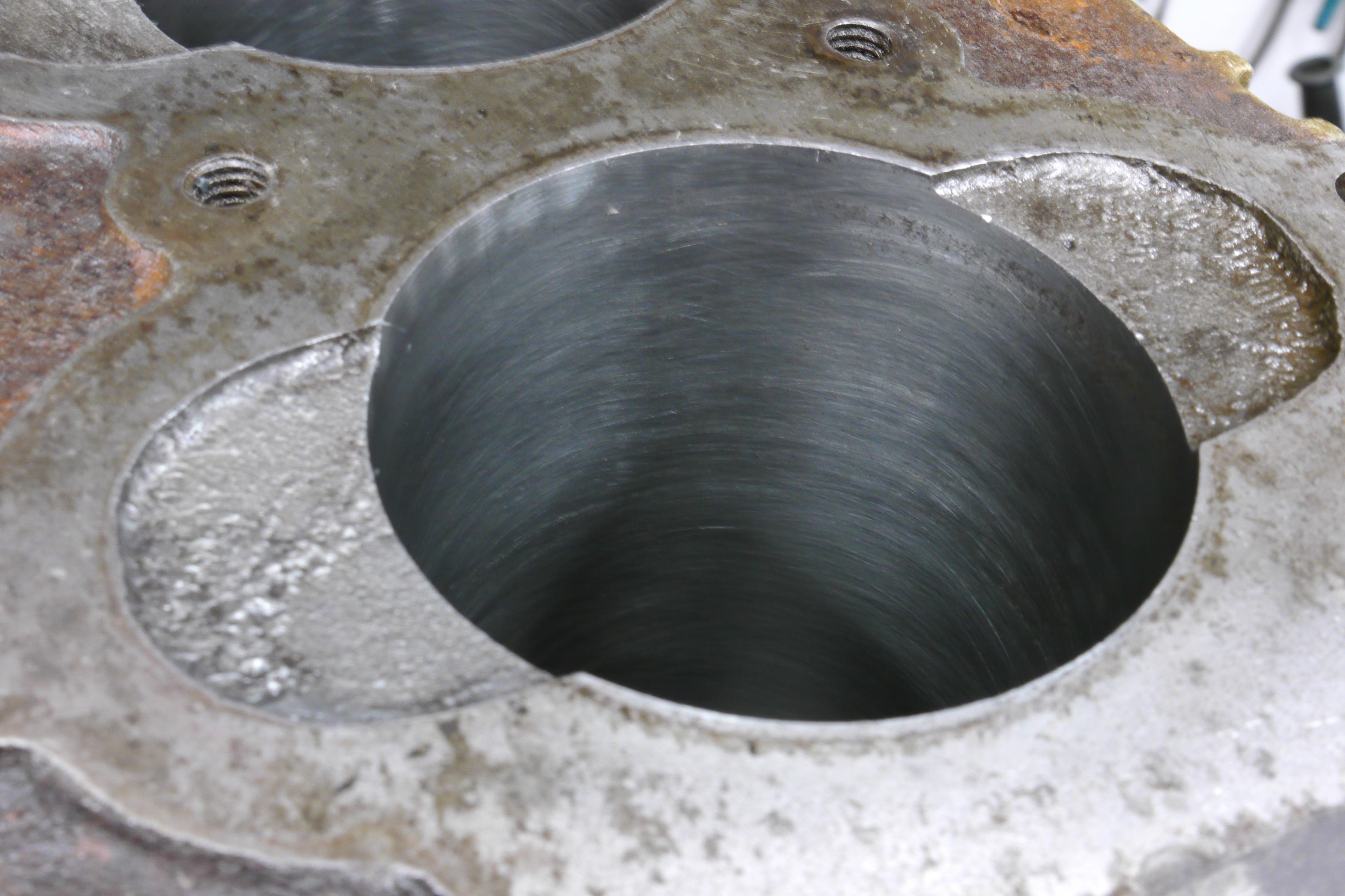
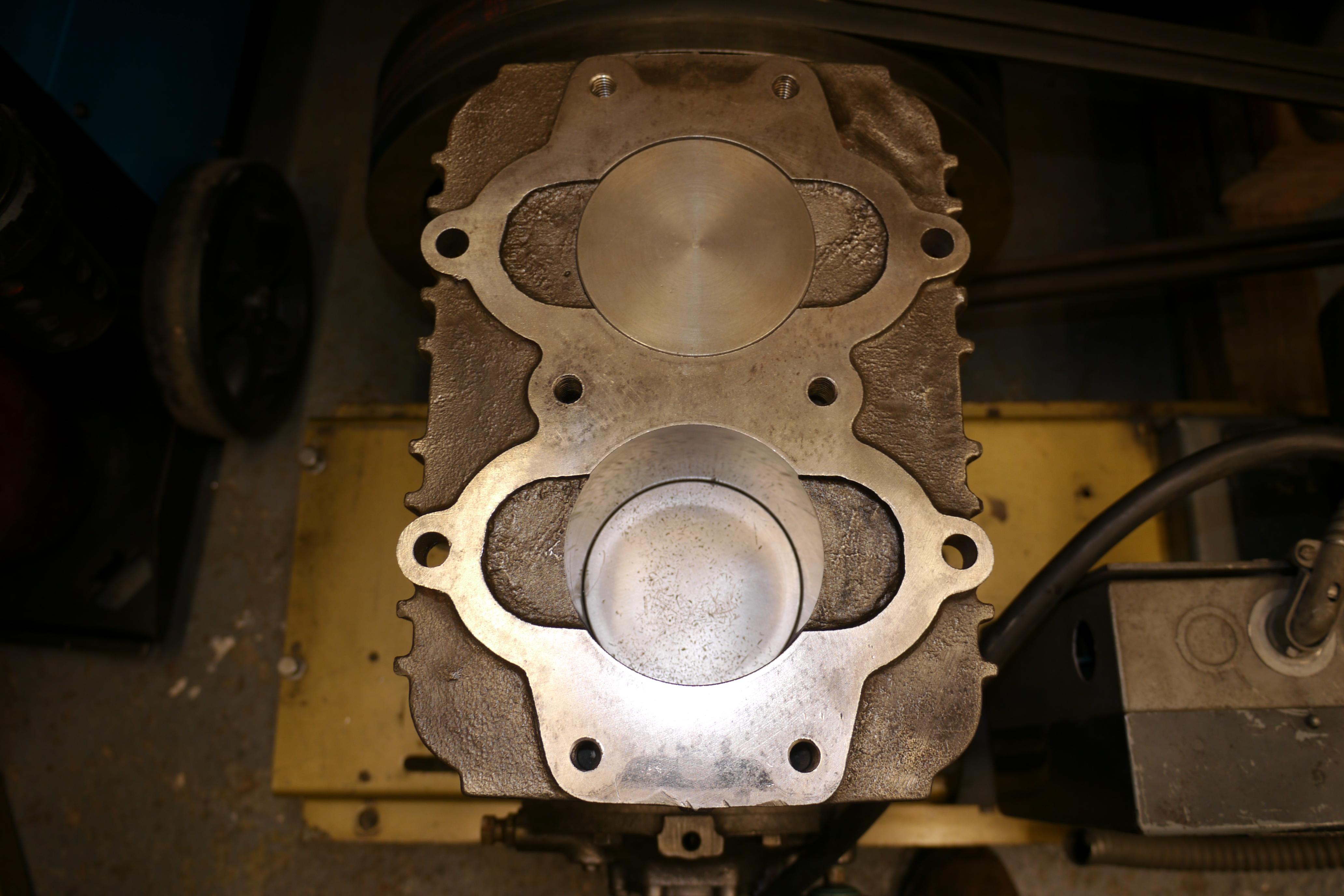
I cleaned the piston domes and the cylinder walls, discovering that this compressor eat something in the past. The cylinders tell quite a story. The concentric bands around the cylinder indicate that the compressor was locked up at one point. The rings essentially rusted to the cylinder wall. The previous owner must have free’ed the compressor up by forcing it to turn with an electric motor. This compressor was definitely used, abused and then left out to rust. Here is the carnage in the rear cylinder.
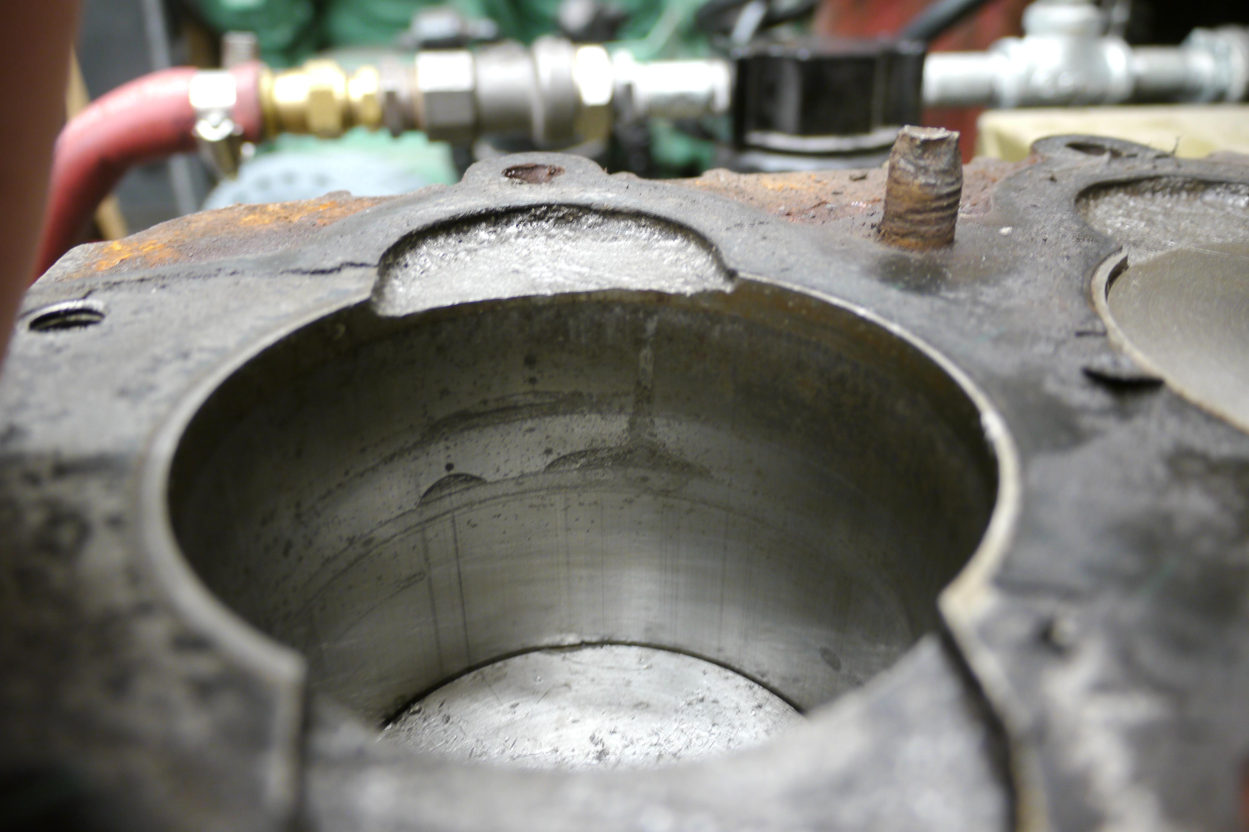
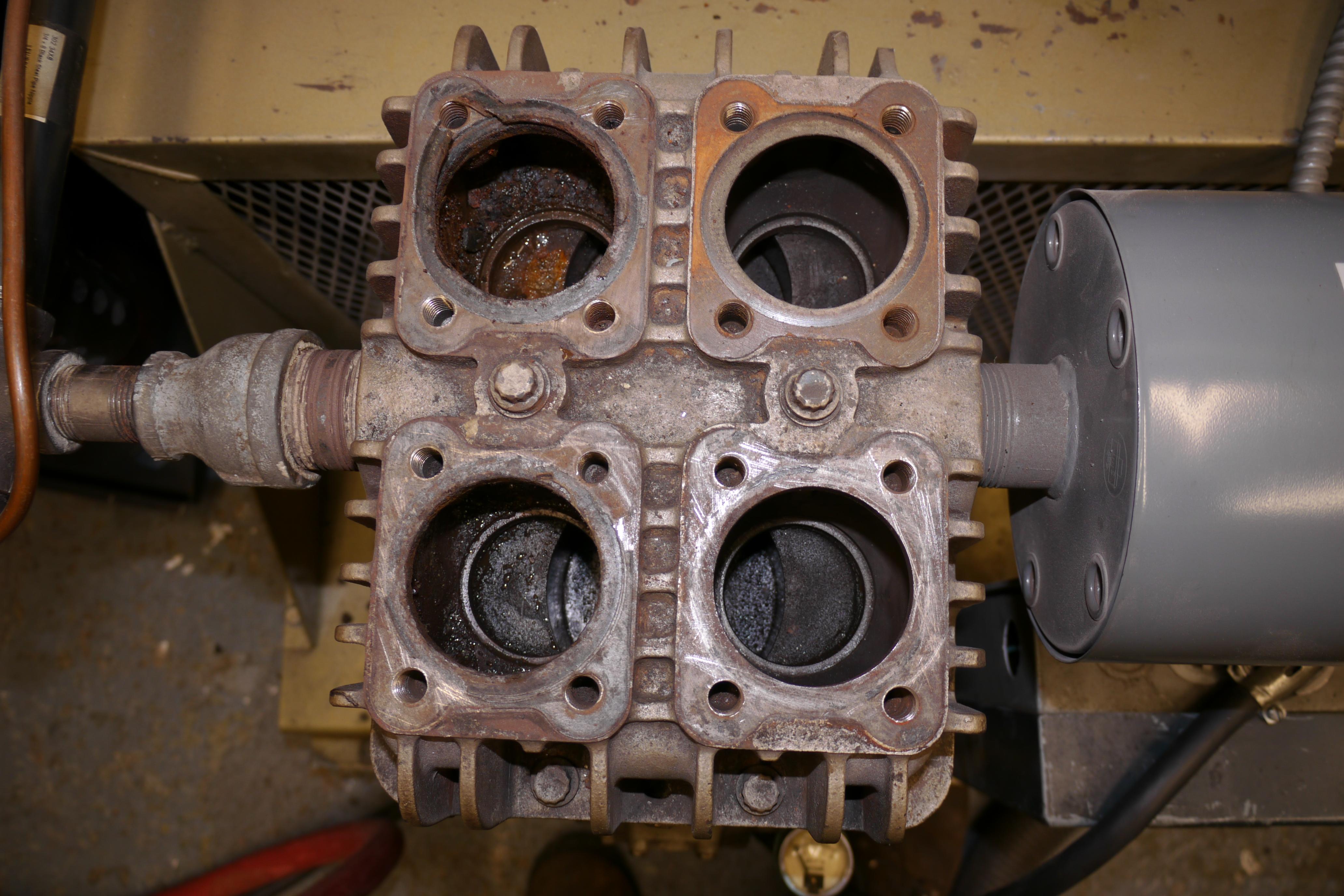
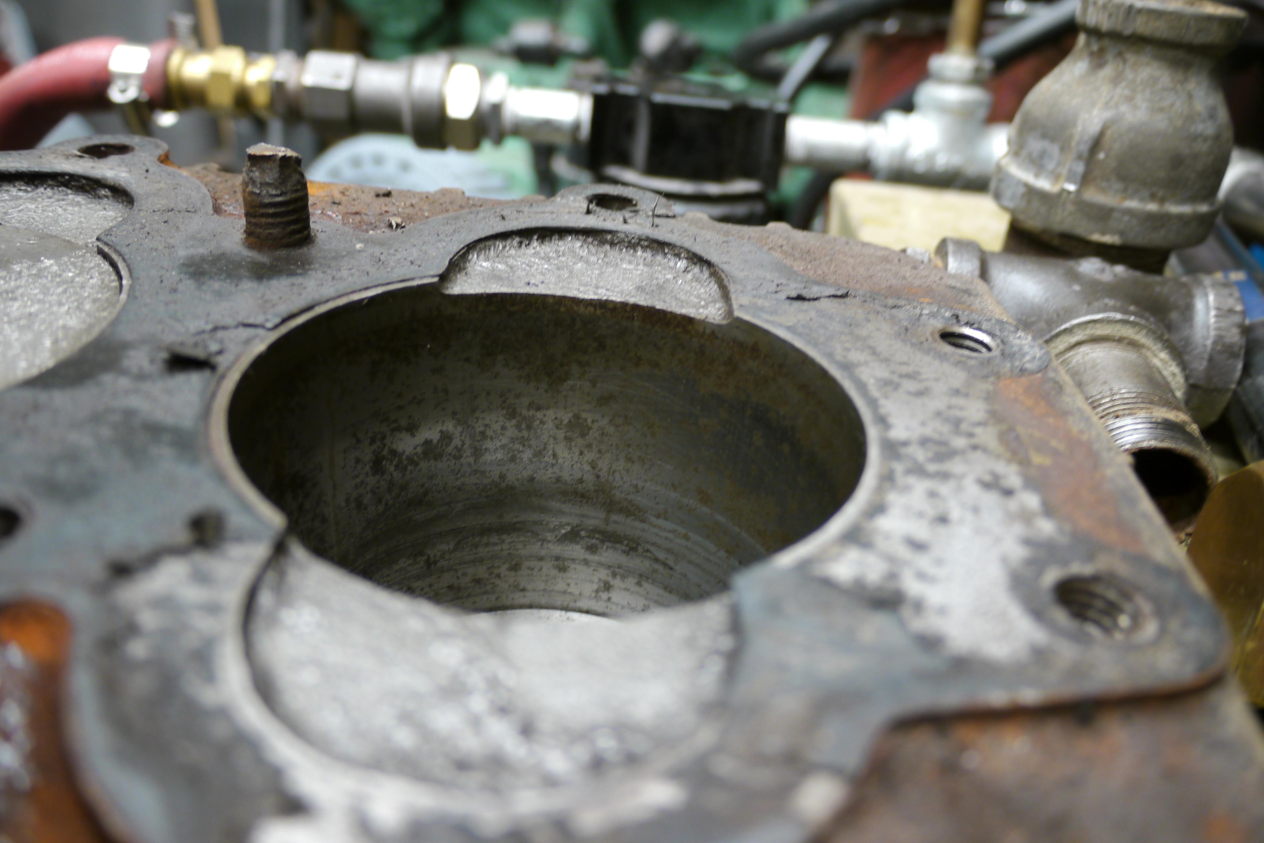
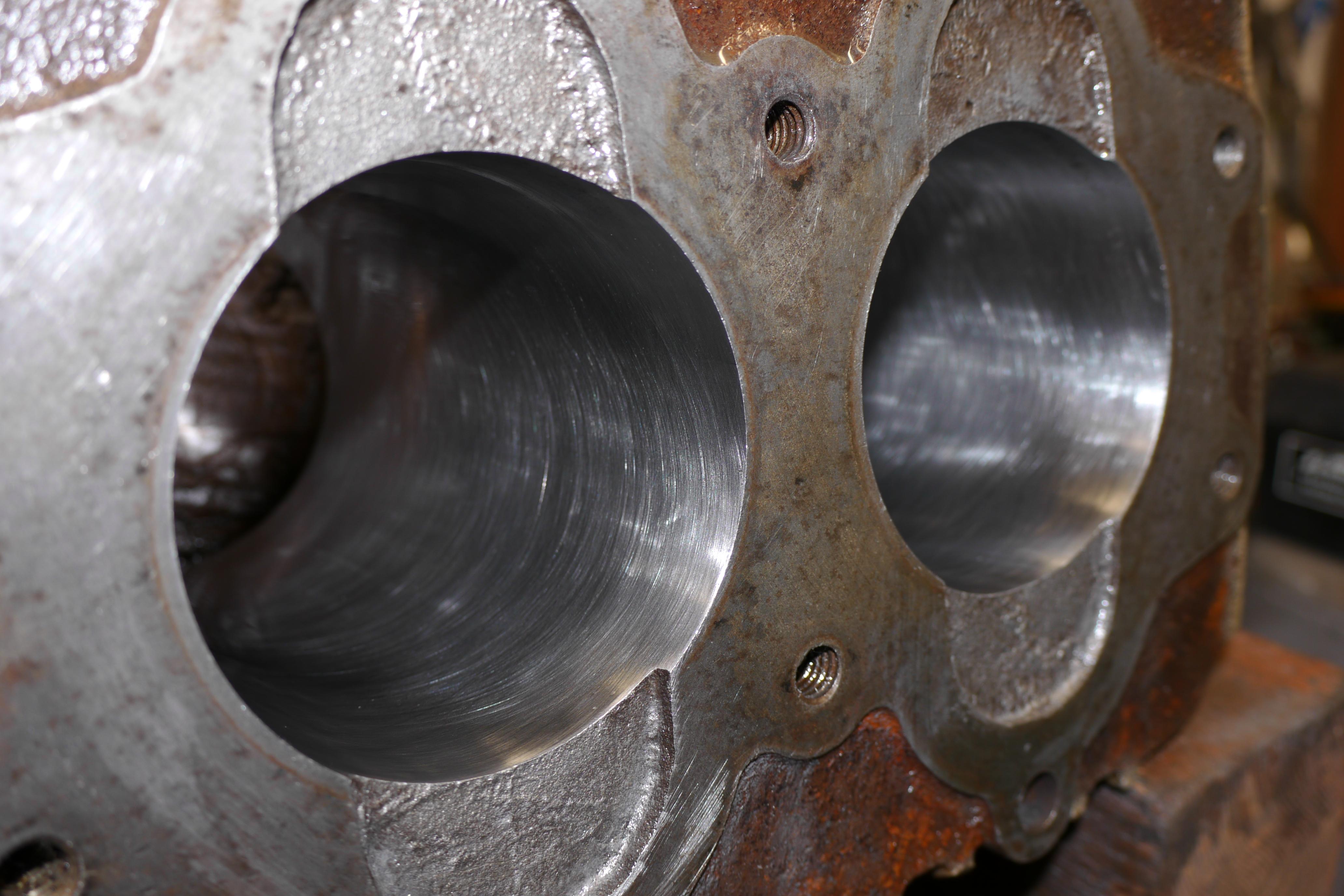
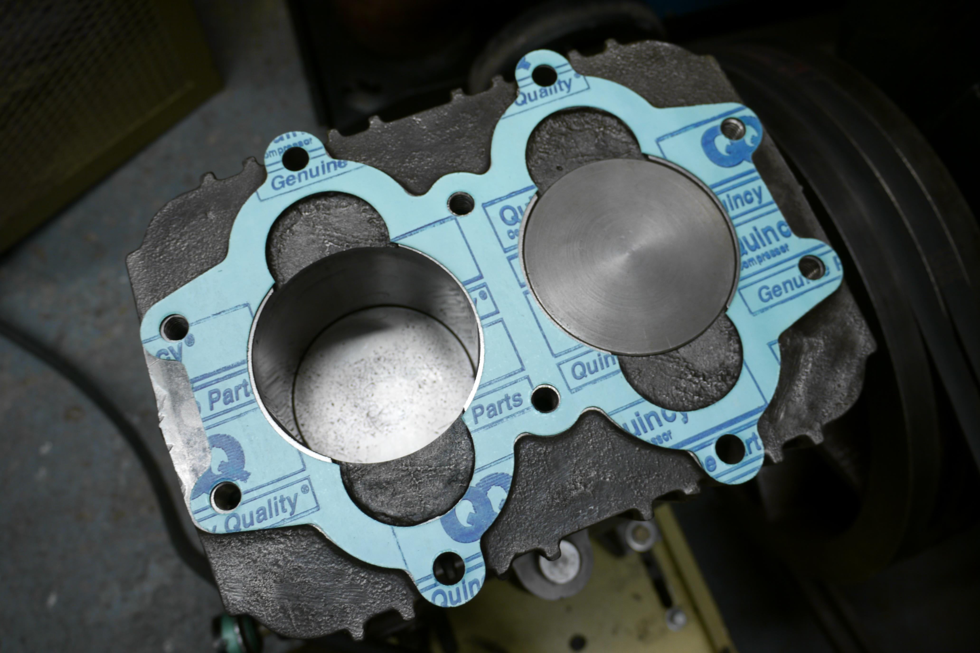
And in the front cylinder:

At this point, the compressor is not looking so good. The valves need to be rebuilt/replaced, the cylinders need to be honed or bored and I might need to replace the pistons and rings. Quincy compressors are not by and means cheap, so this will surely be an expensive rebuild. Without anything to loose, I hooked up my blast cabinet to my 1953 US Navy issue Devilbiss gasoline powered air compressor, and began bead blasting the valves. My Devilbiss compressor has a 32cfm capacity, which makes quick work of media blasting. Media blasting is almost as rewarding as painting. The result is nearly instant and so gratifying. I use Clemco Zero 801210 military grade glass bead. I was able to knock all of the rust, scale and debris from the valves and cylinder head in a short amount of time.

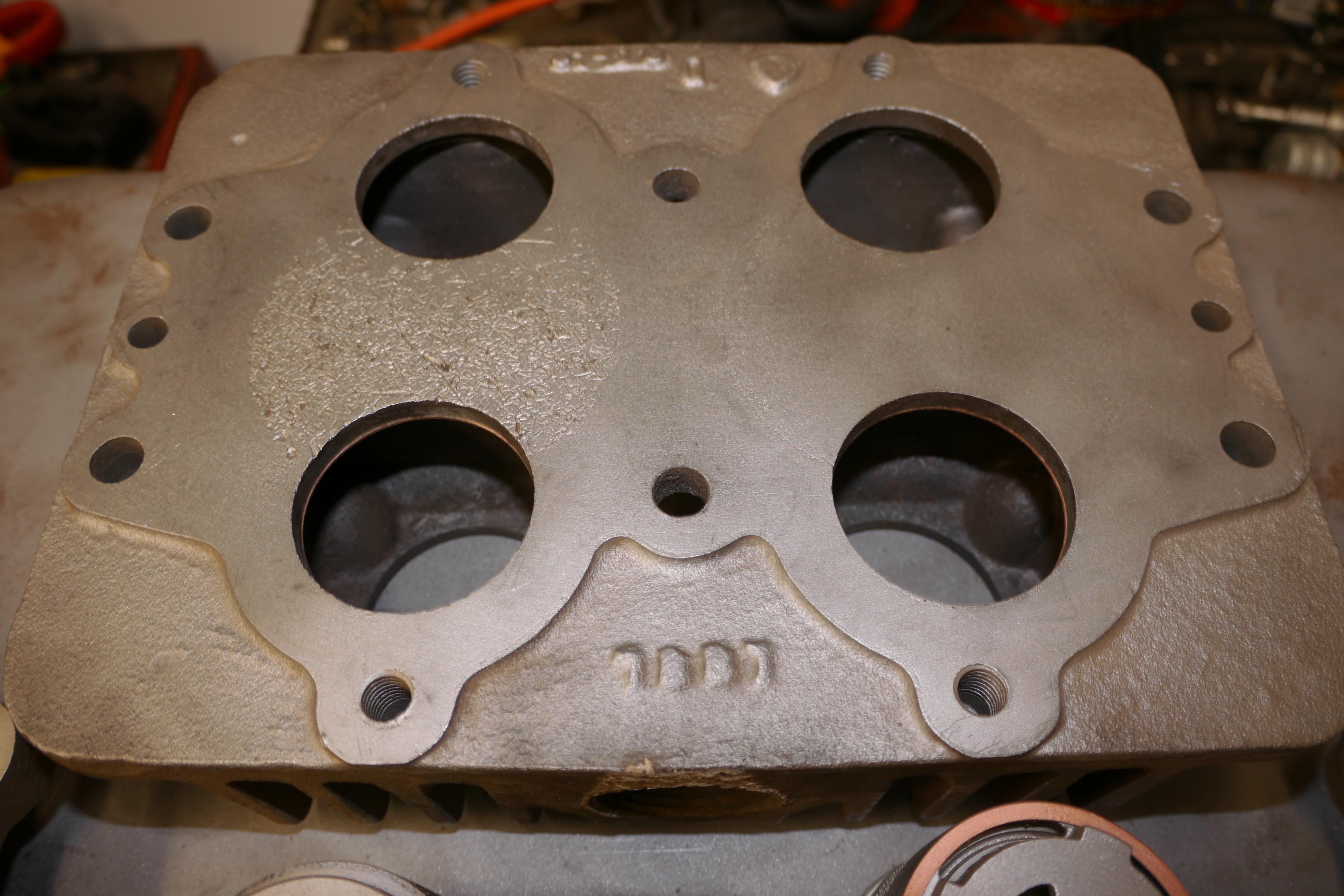
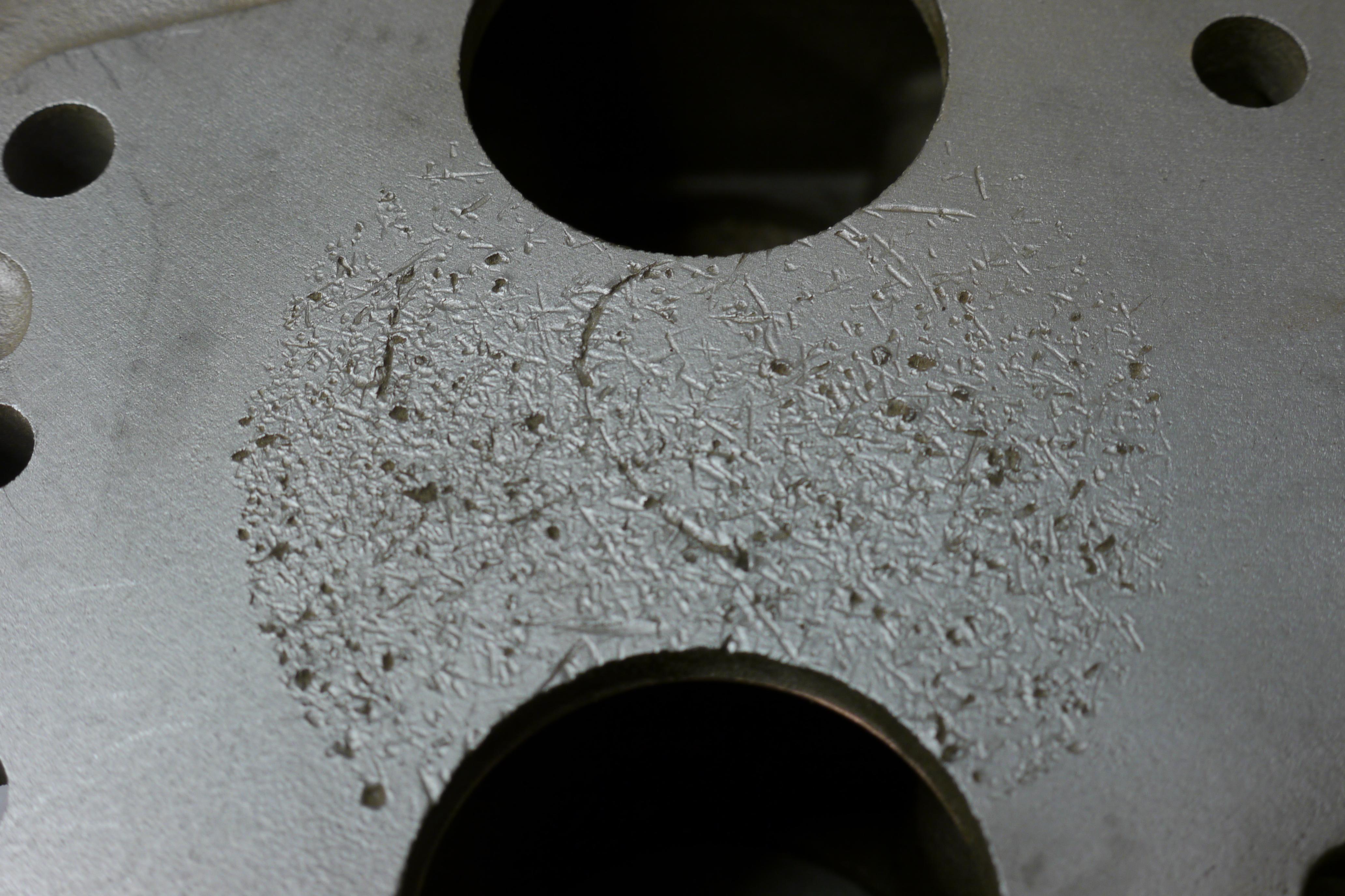
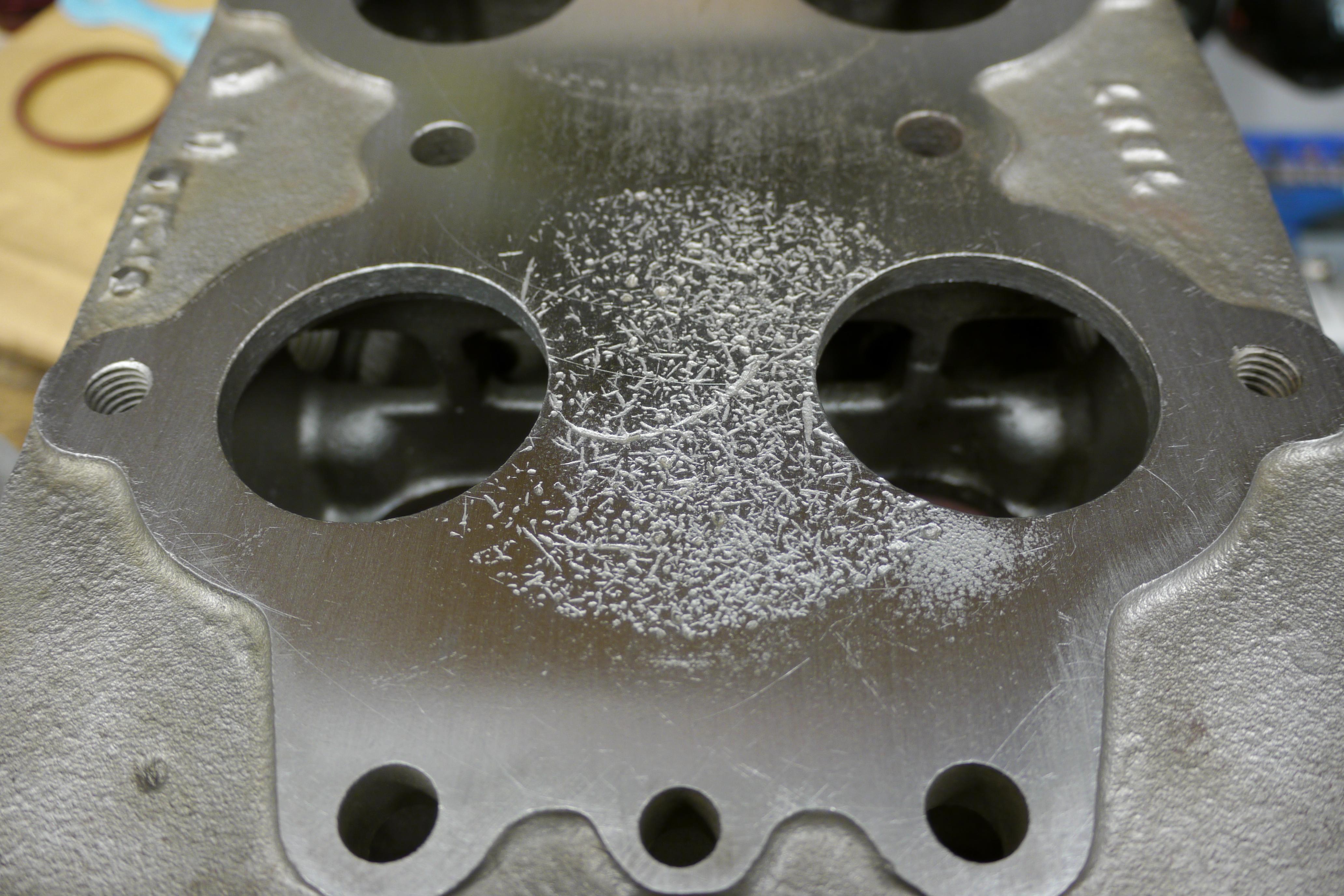
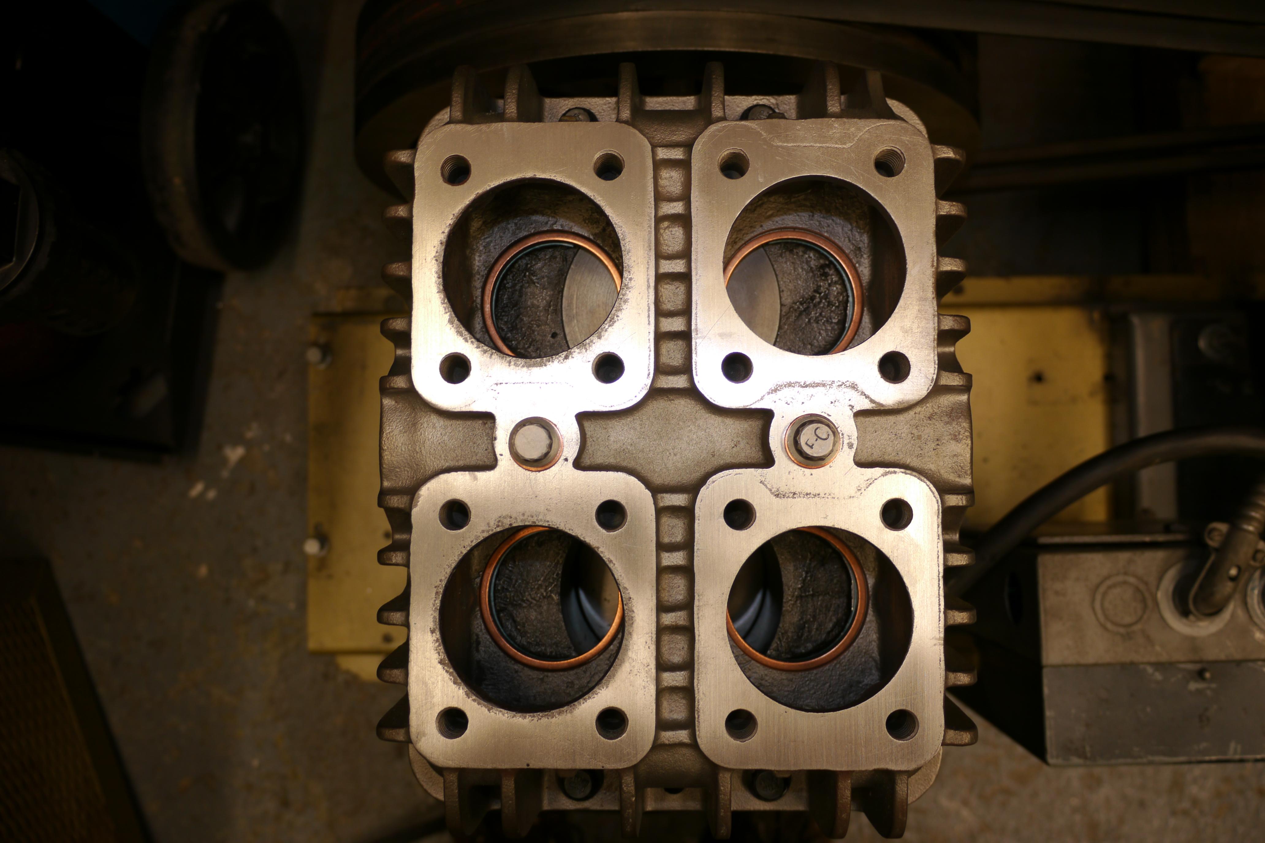
The old parts are now clean as a whistle, and ready to be inspected. The cylinder head shows all of the tell tale signs of a discharge valve failure. Inadequate tension on the discharge valve likely caused the valve body to vibrate with excessive force, shattering the discharge valve disc. The hardened steel valve disc was clearly dancing around in the cylinder before being broken into pieces small enough to exit the cylinder head. Luckily the pitting is not too severe, resurfacing the cylinder head and piston might render the parts useable again. Some preliminary blasting around the recessed shoulder which the valves sit on reveals that the valves were not over-torqued at any point. I am told by the local compressor shop that over-torquing the valves can result in the bottom of the cylinder head blowing out.
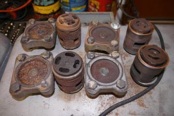
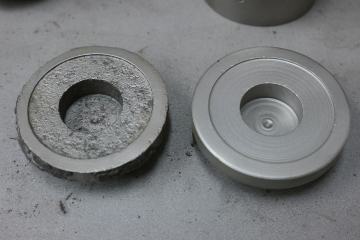
Media blasting the valve bodies and spacers revealed quite a bit of wear all around. Both of the discharge valve spacers were completely eroded away, and both of the discharge valve bodies were heavily pitted.
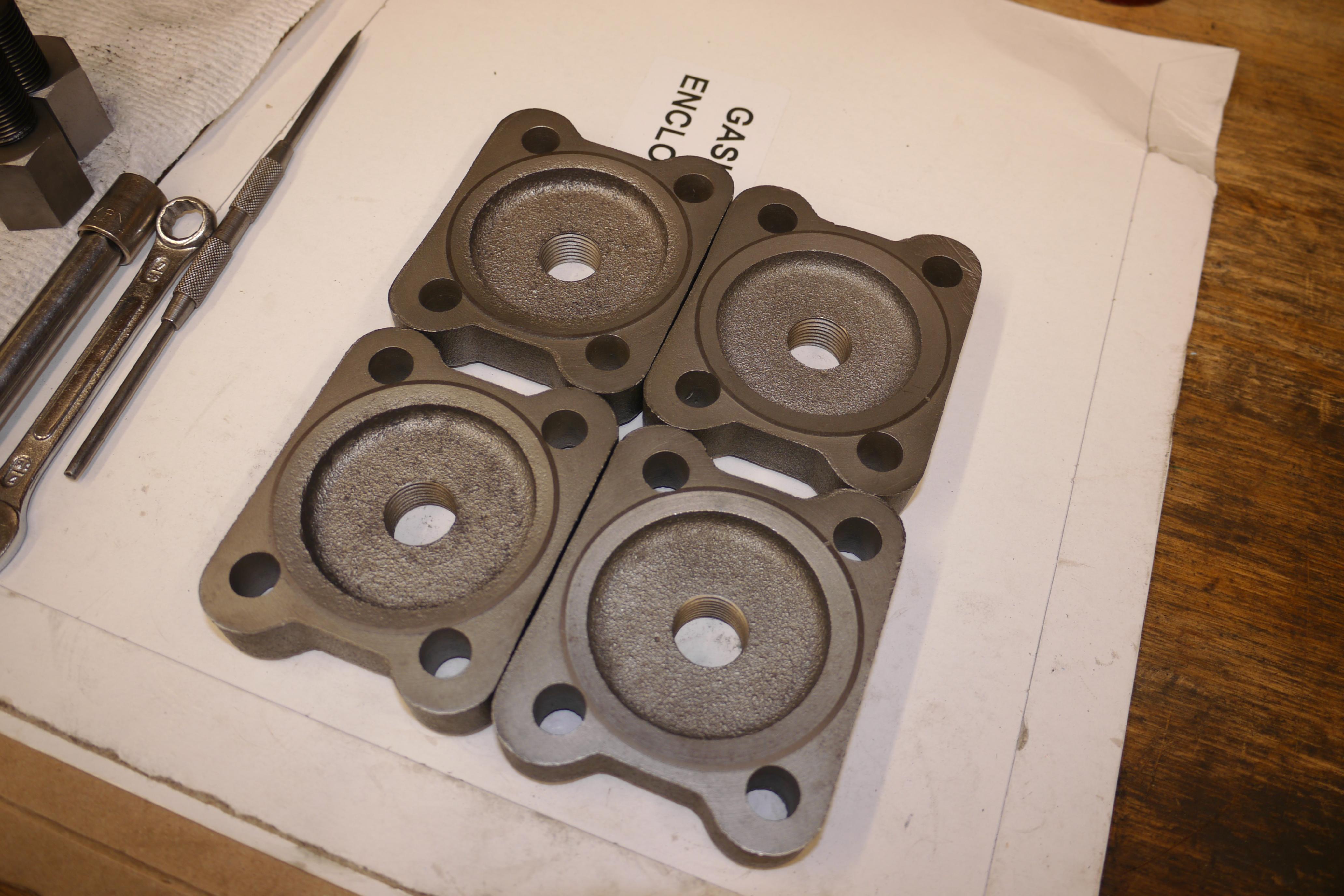
The valve covers themselves were internally pitted with the discharge valve covers significantly more eroded than the intake valve covers.
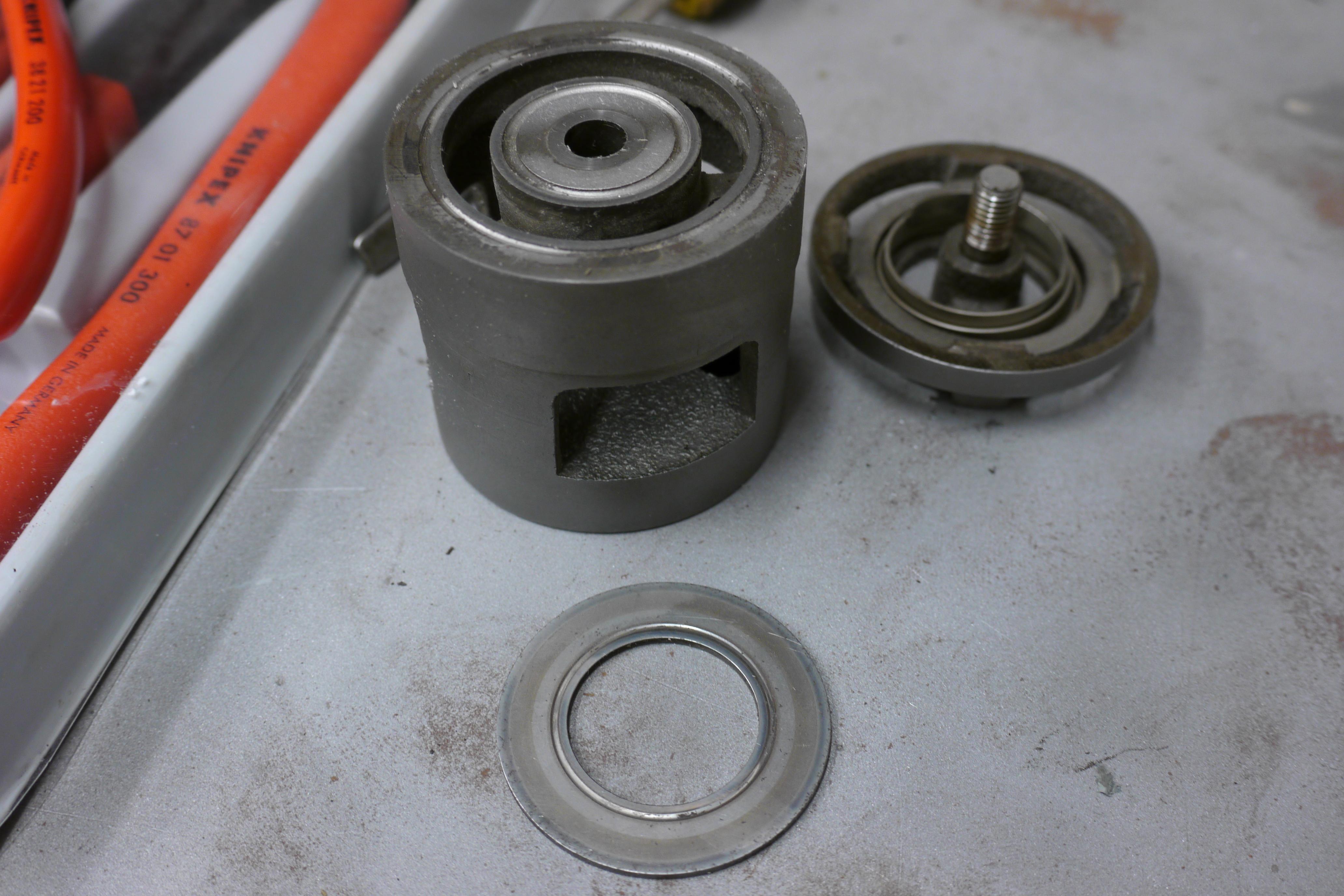
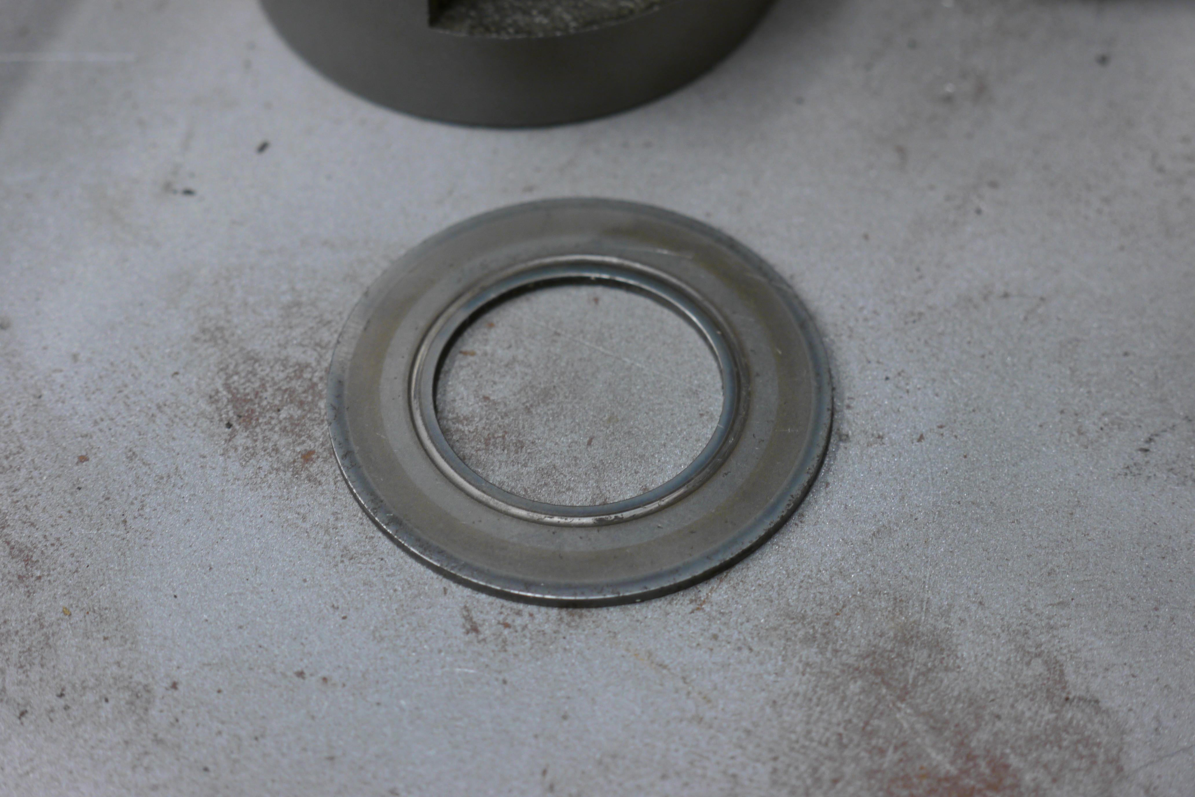
Dismantling the discharge valve bodies revealed how much internal wear there was on these parts. The valve posts (bolt’s) which run through the center of the valve body were heavily rusted and were quite difficult to remove through the small hole in the top of the valve body. Removing the post unscrews the discharge valve seat from the valve body, exposing the discharge valve itself and the discharge valve spring. All of these parts were heavily corroded by the moisture inherently produced by the process of compressing air.
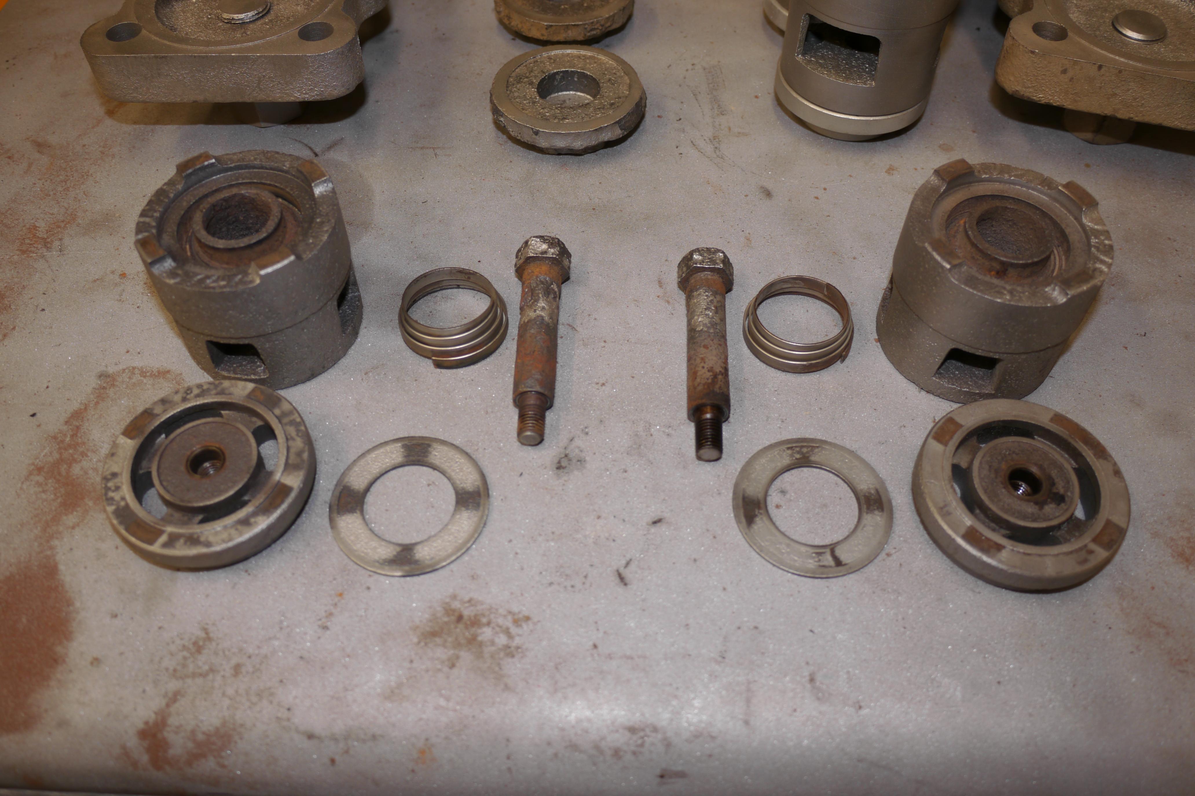

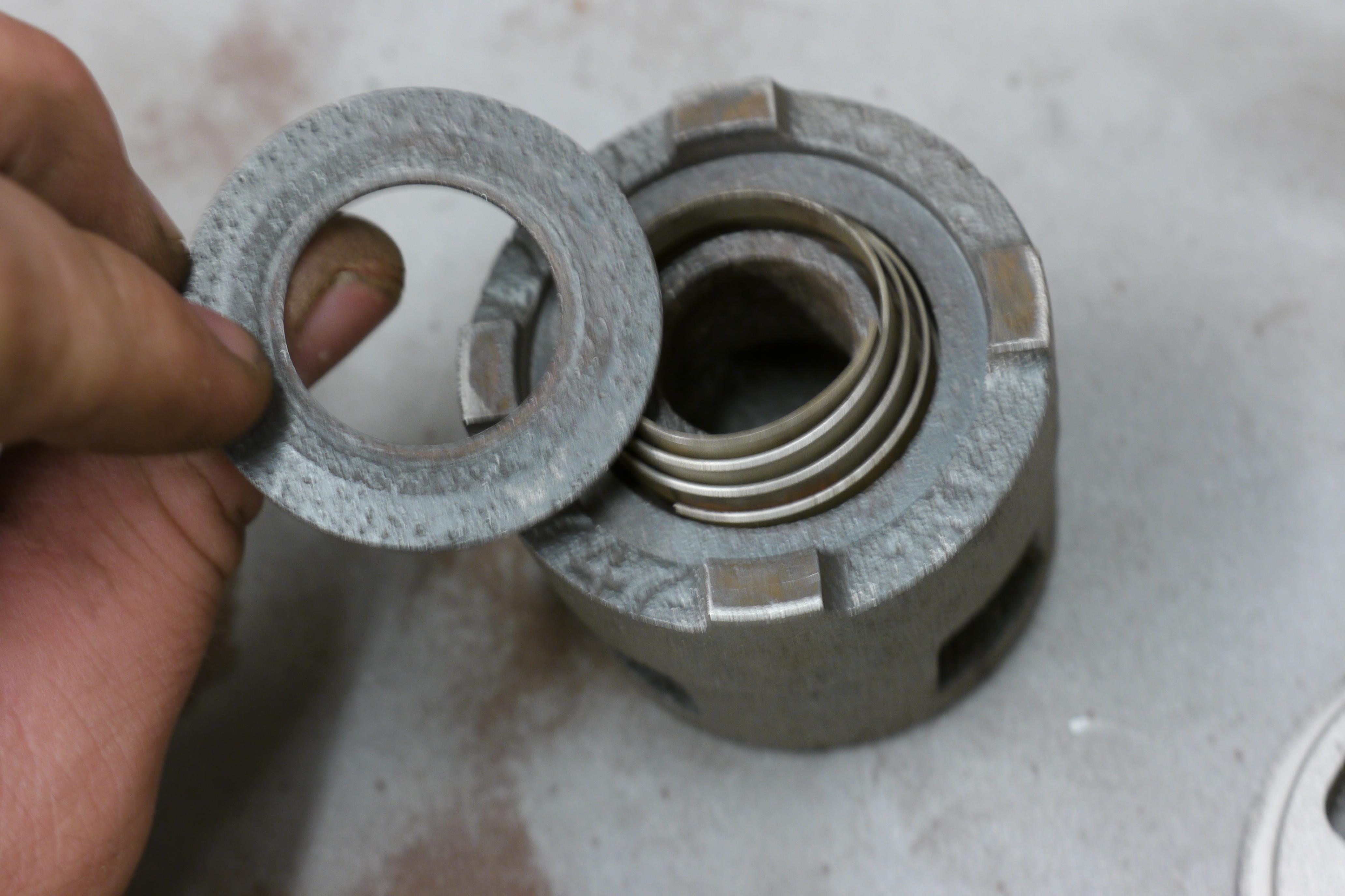

The intake valves were in slightly better cosmetic condition, however dismantling them revealed where the ticking noise was coming from. After unscrewing the intake valve bumper from the body and seat, it was apparent that the intake valves were extremely worn. The valve spring had worn a groove nearly all of the way through the valve disc!
Knowing that the valves will need to be completely rebuilt with new bumpers, seats, springs and discs I continued to pull the compressor apart. There was just no sense in simply rebuilding the cylinder head if the rest of the compressor was equally as worn. As you recall, one of the cylinder head bolts had sheared off. I was able to weld a nut to the broken off stub, and with a little additional heat around the threaded hole, I was able to remove the stubborn end of the bolt.

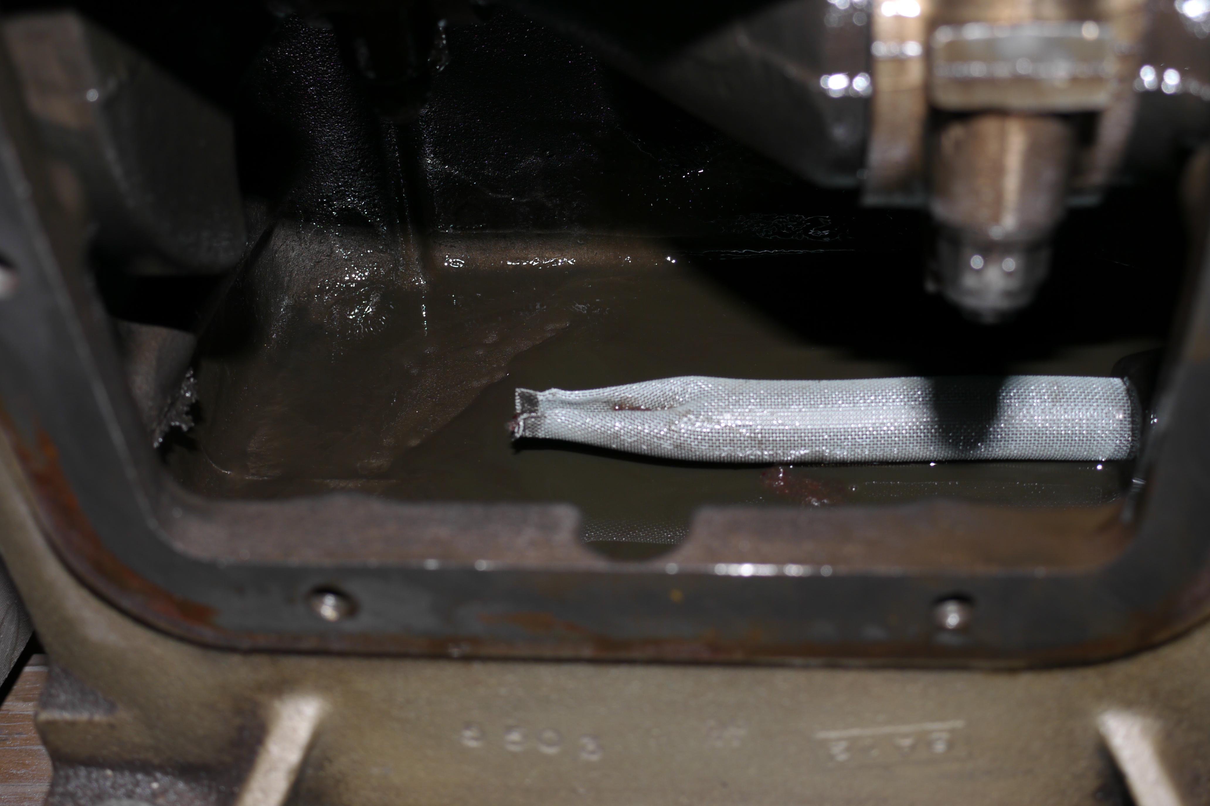
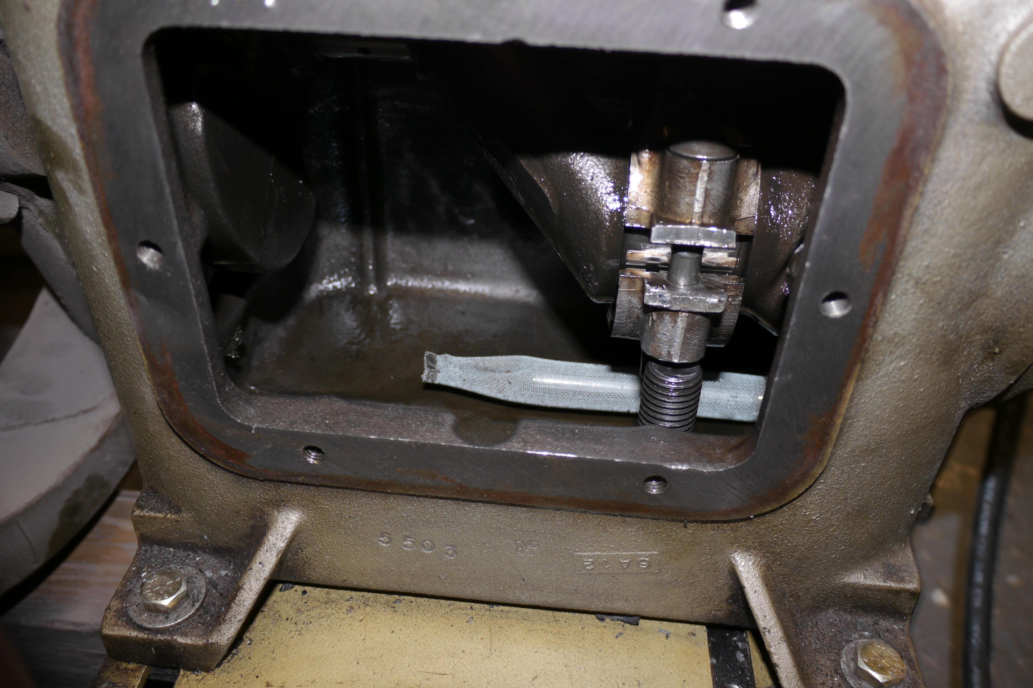
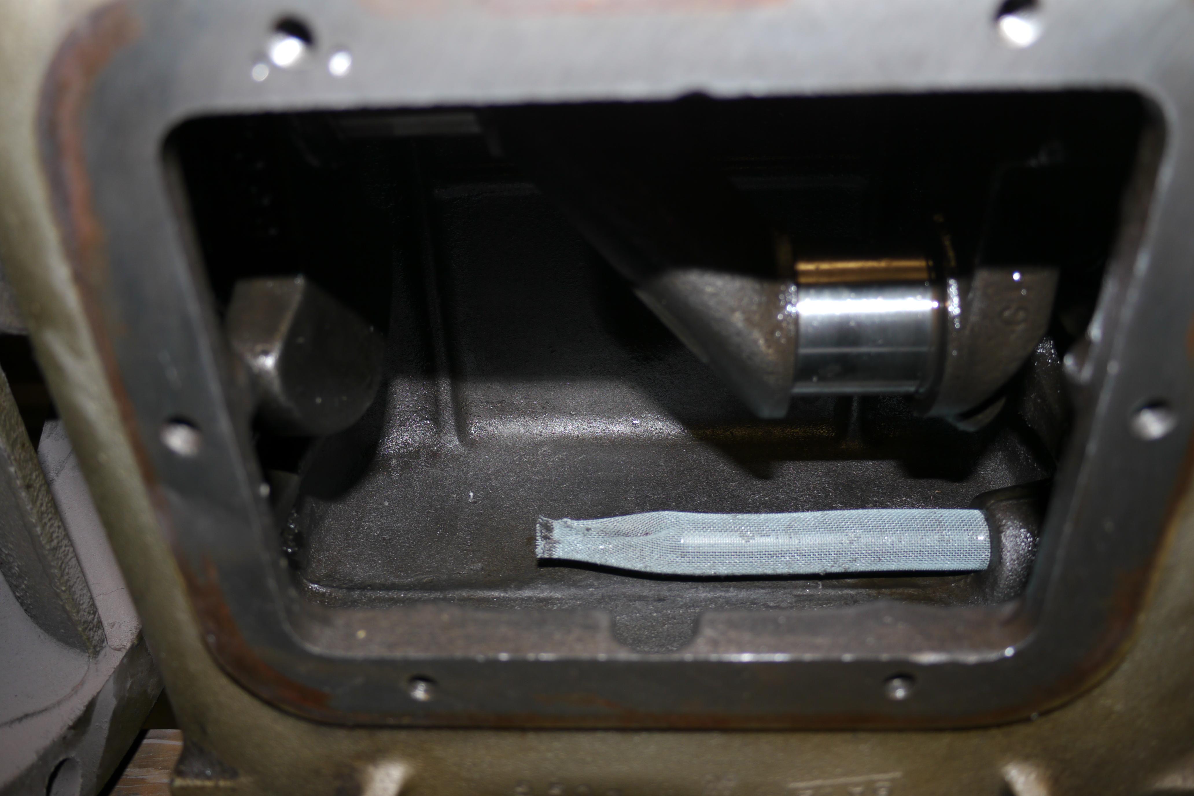
The next step was to remove the pistons from the compressor. In order to do so, you have to remove the inspection cover on the side of the compressor, and remove the lock nuts on the end of the connecting rod caps. I took this opportunity to clean out all of the old oil and sludge from the inside of the compressor. Quincy uses a mesh screen to keep any large contaminants out of the oil pump. Removing the connecting rod caps is easier said then done. First you need to rotate the crankshaft so that the crank throws are horizontal. Then you need to wedge a solid object, a bolt or socket underneath the connecting rod bolt, so that when the crankshaft is turned the bolt will push down on the solid object below, pushing the bolt through the top of the connecting rod. Once both of the connecting rod bolts are pushed through the top of the connecting rod, you will be able to remove the connecting rod cap and remove the connecting rod and piston from the cylinder.
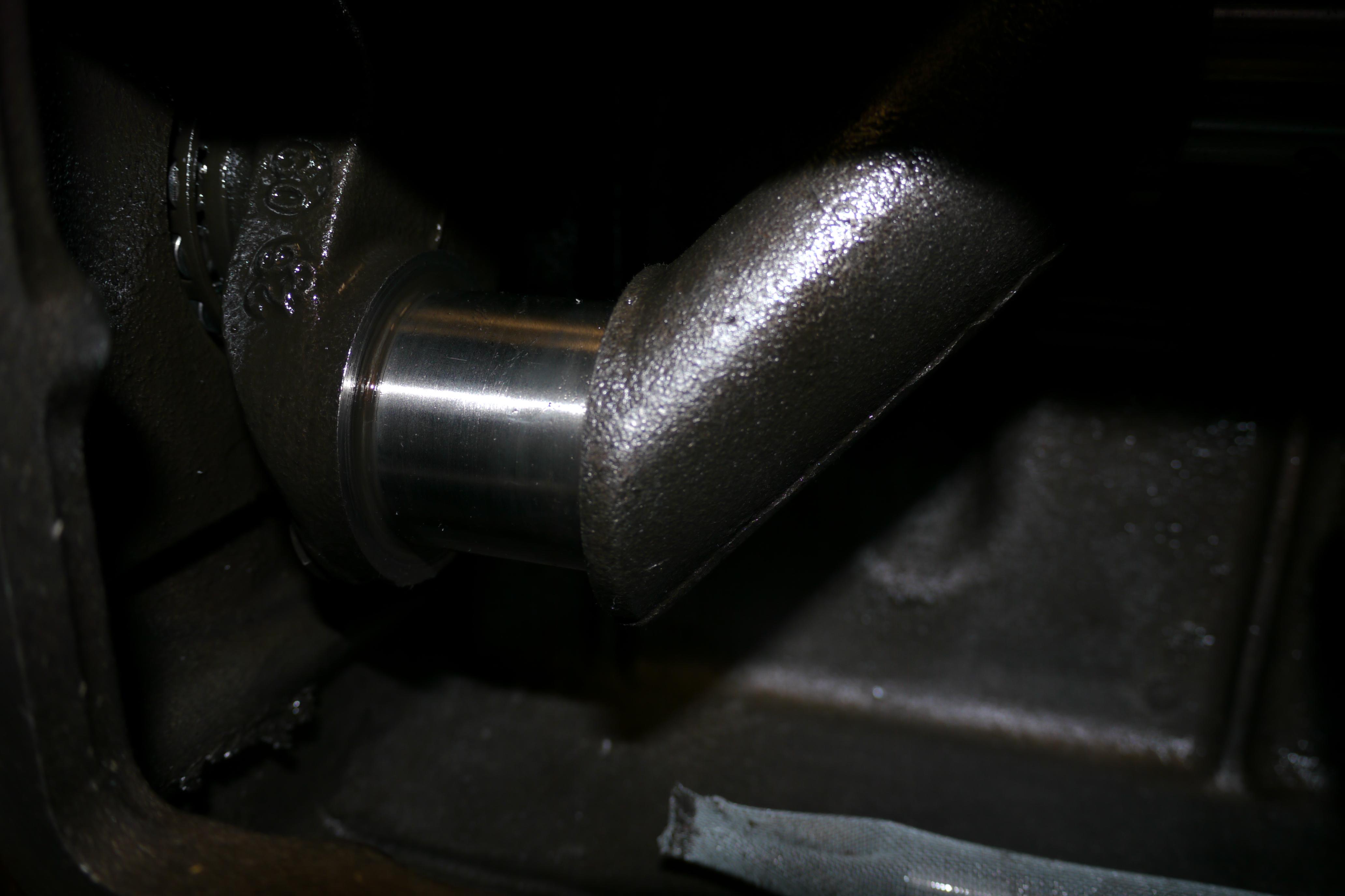
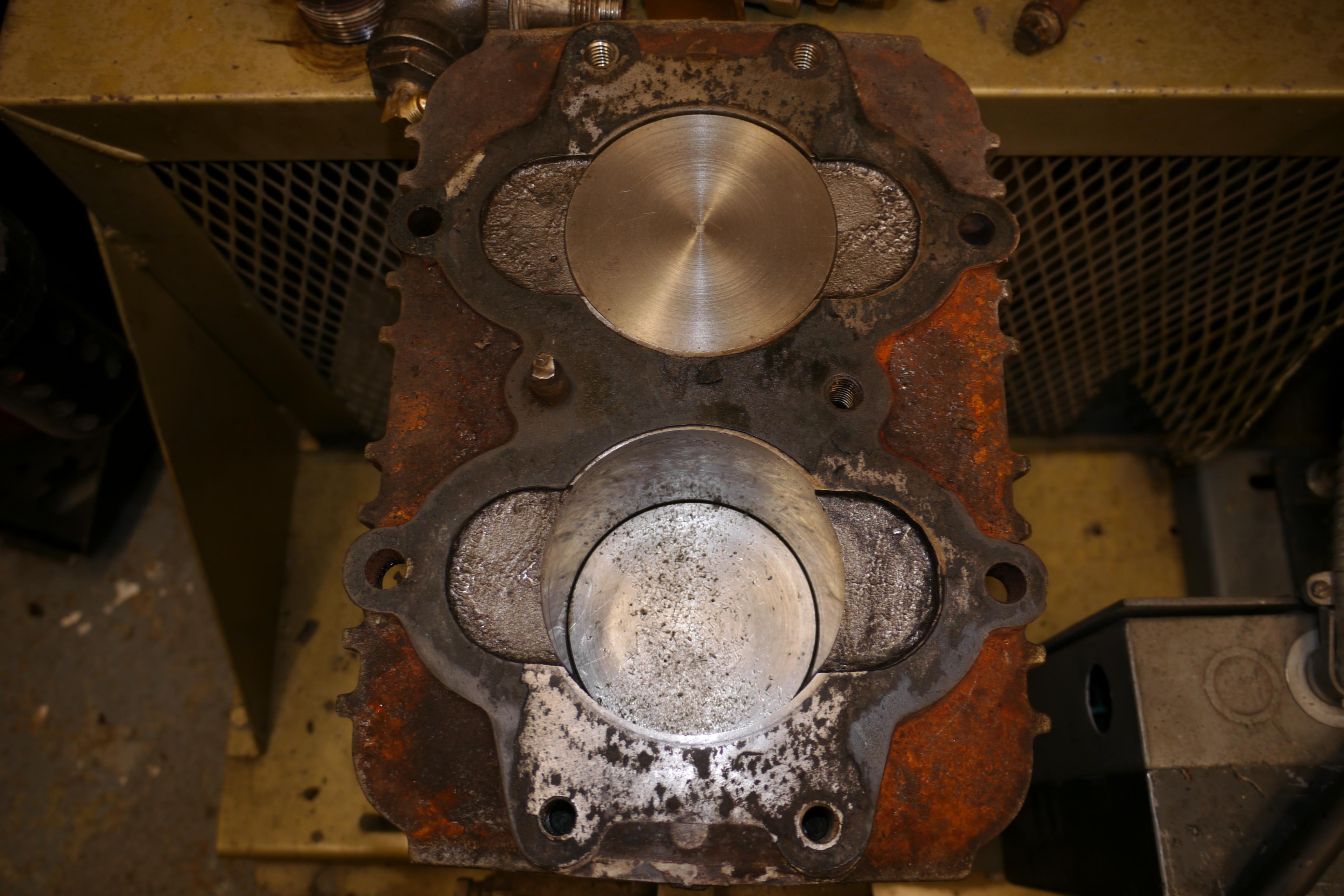
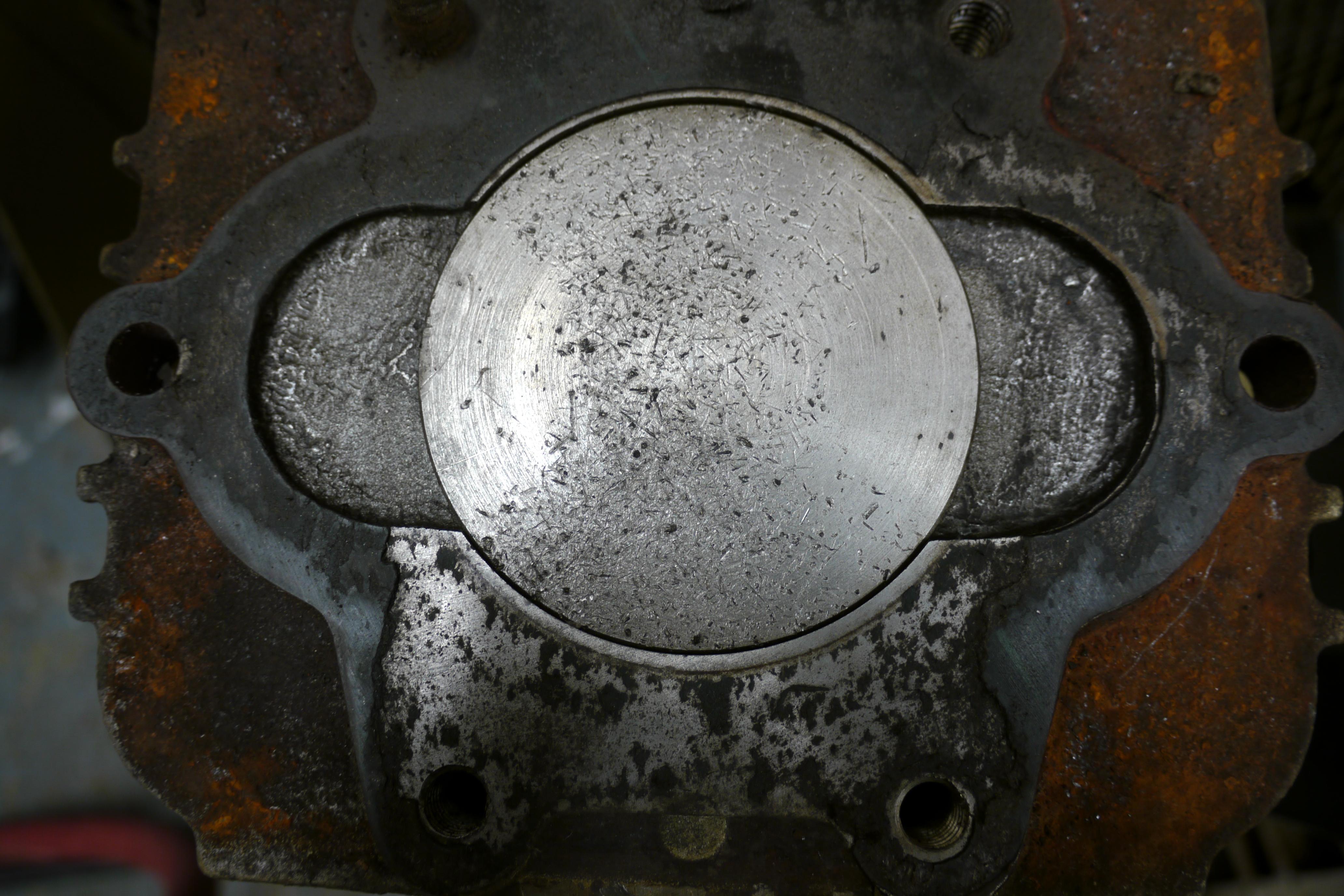
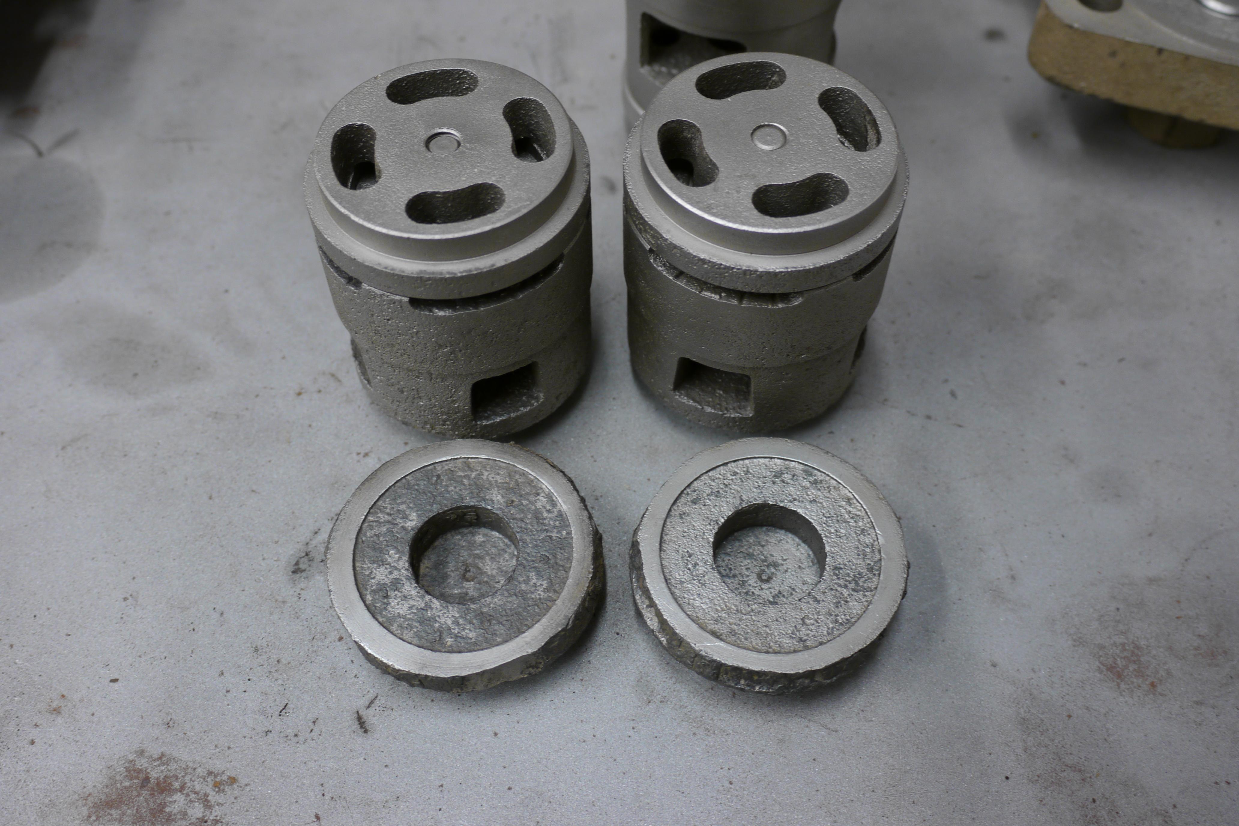
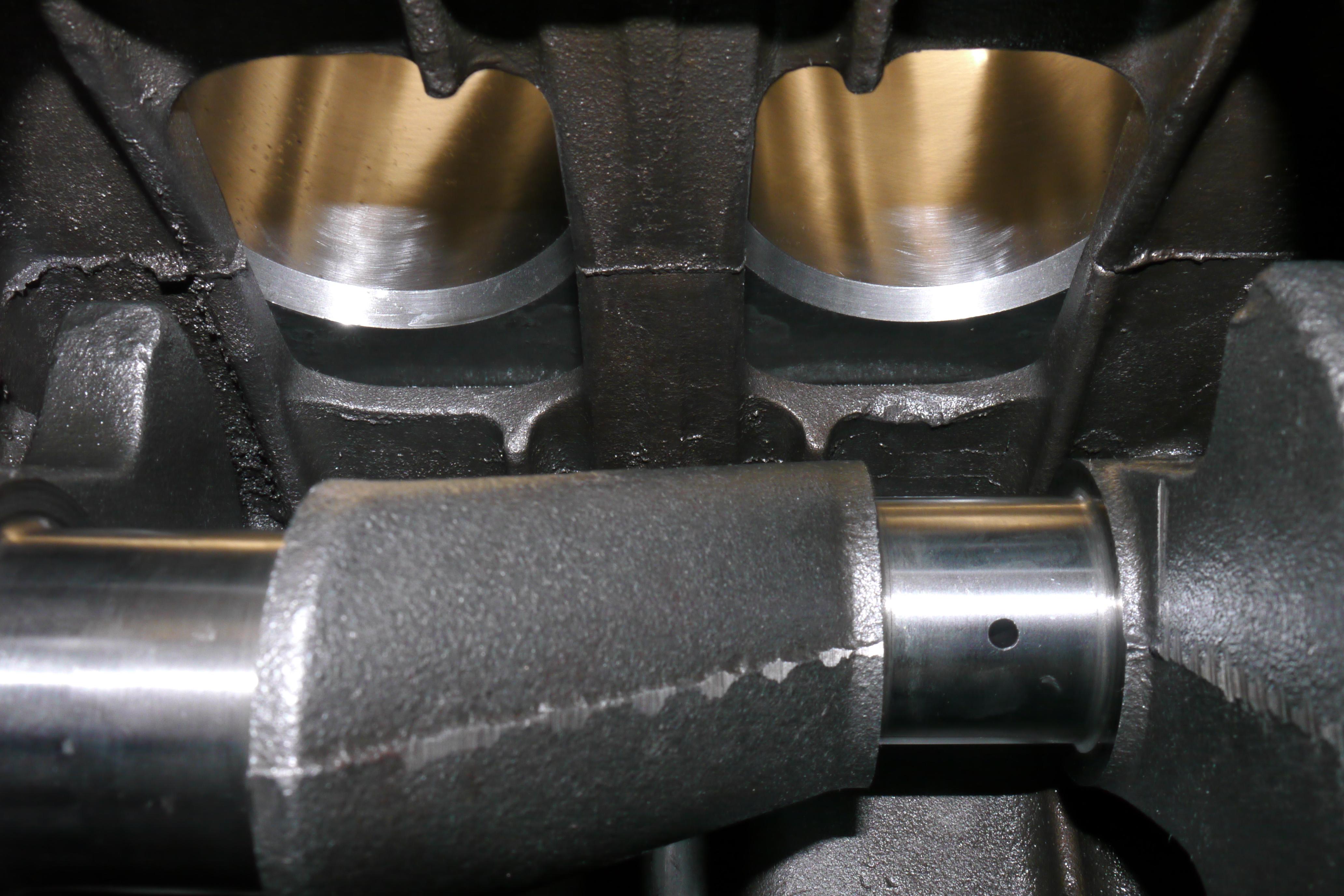
Quincy uses a pretty stout single plane crankshaft in their twin cylinder compressors, supported by Timken tapered roller bearing mains. The crankpins were in fantastic shape, which is almost hard to believe considering the condition of the rest of the compressor. The cylinders on the other hand looked absolutely terrible. There was so much surface rust and evidence that the piston rings seized in their bores that it was amazing that this compressor still ran and compressed air just fine.

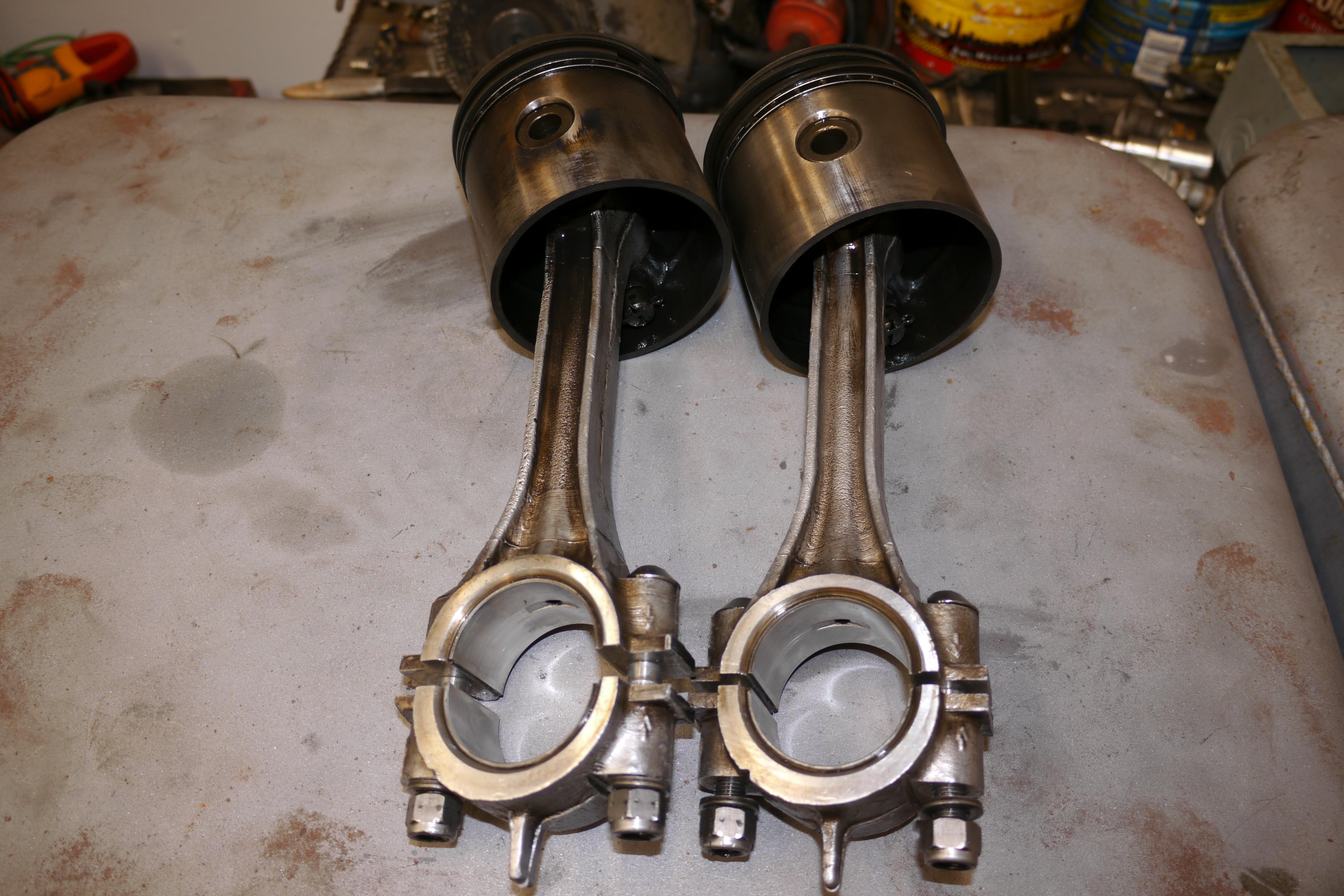
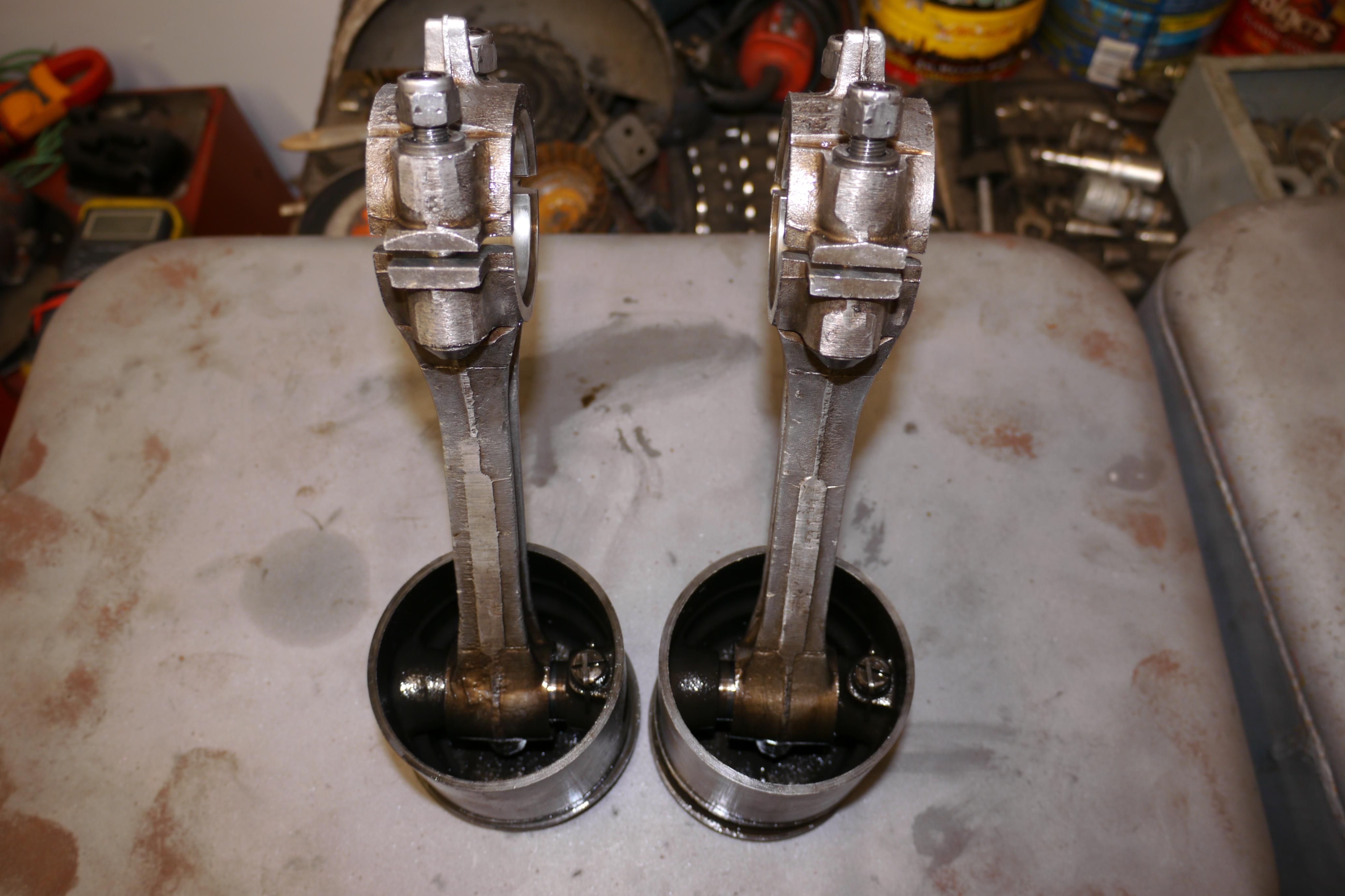
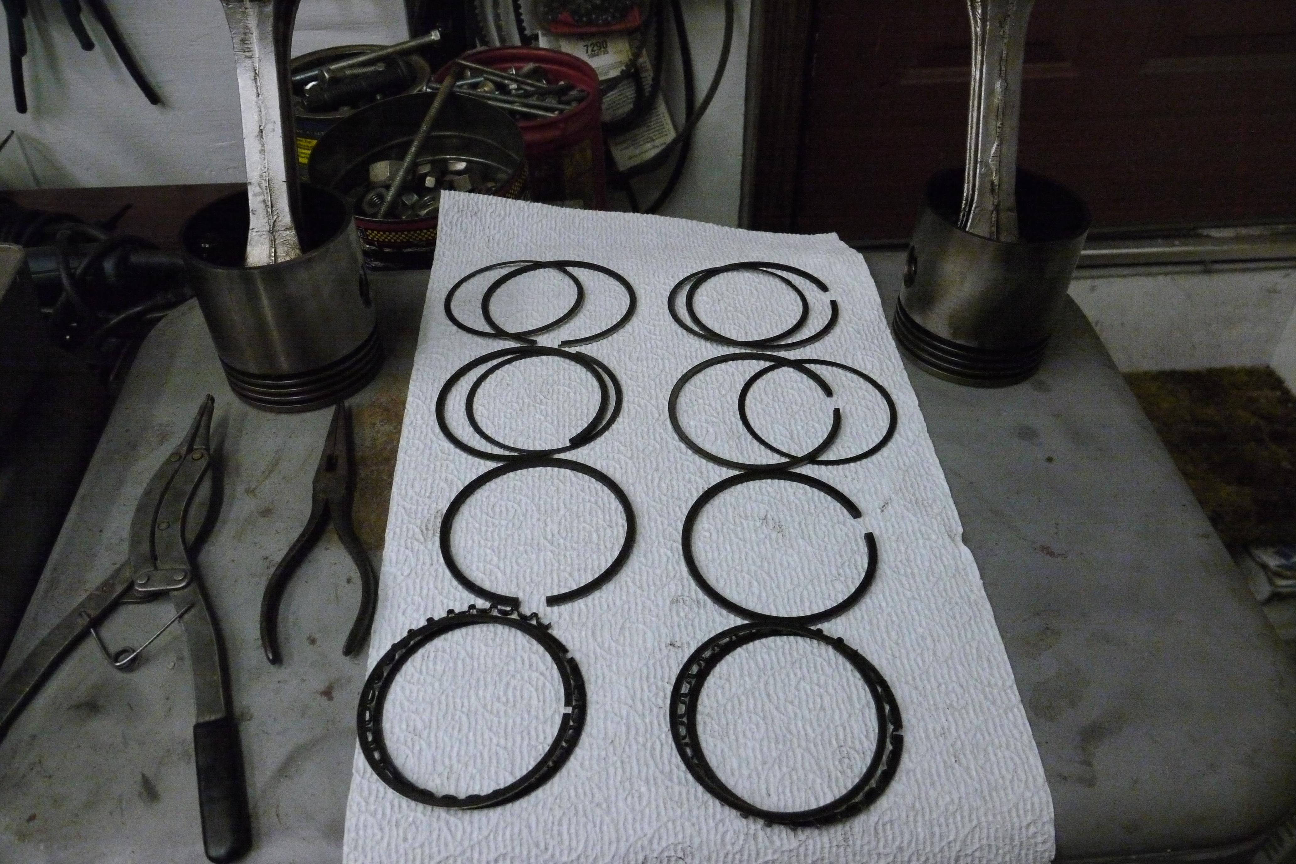
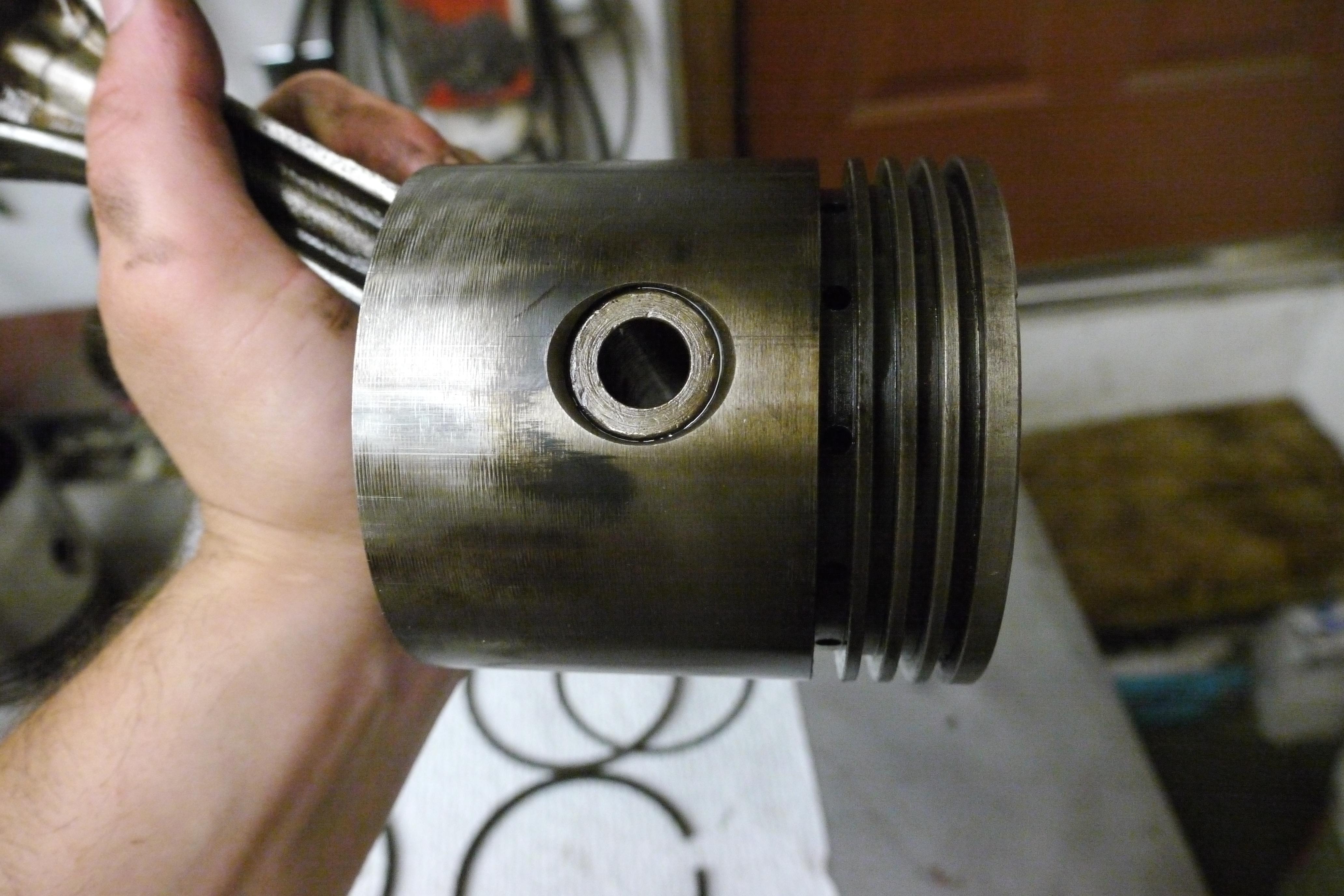
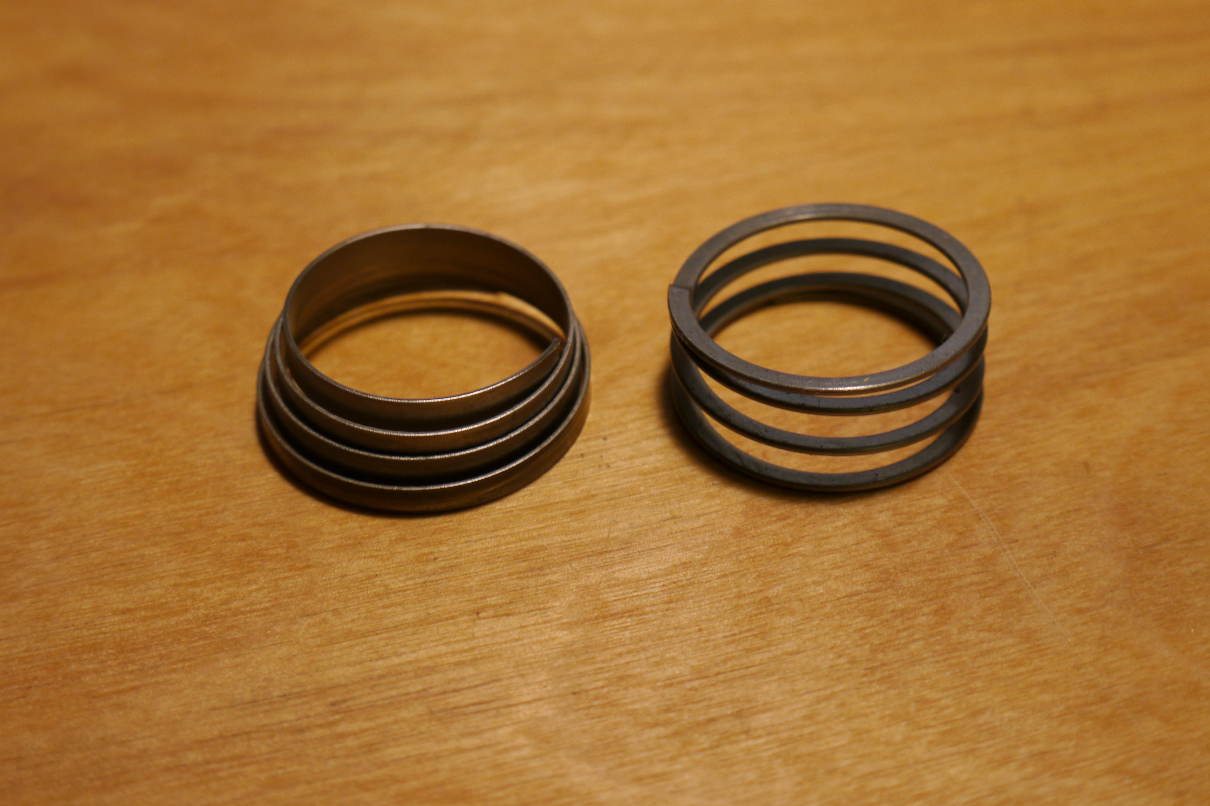
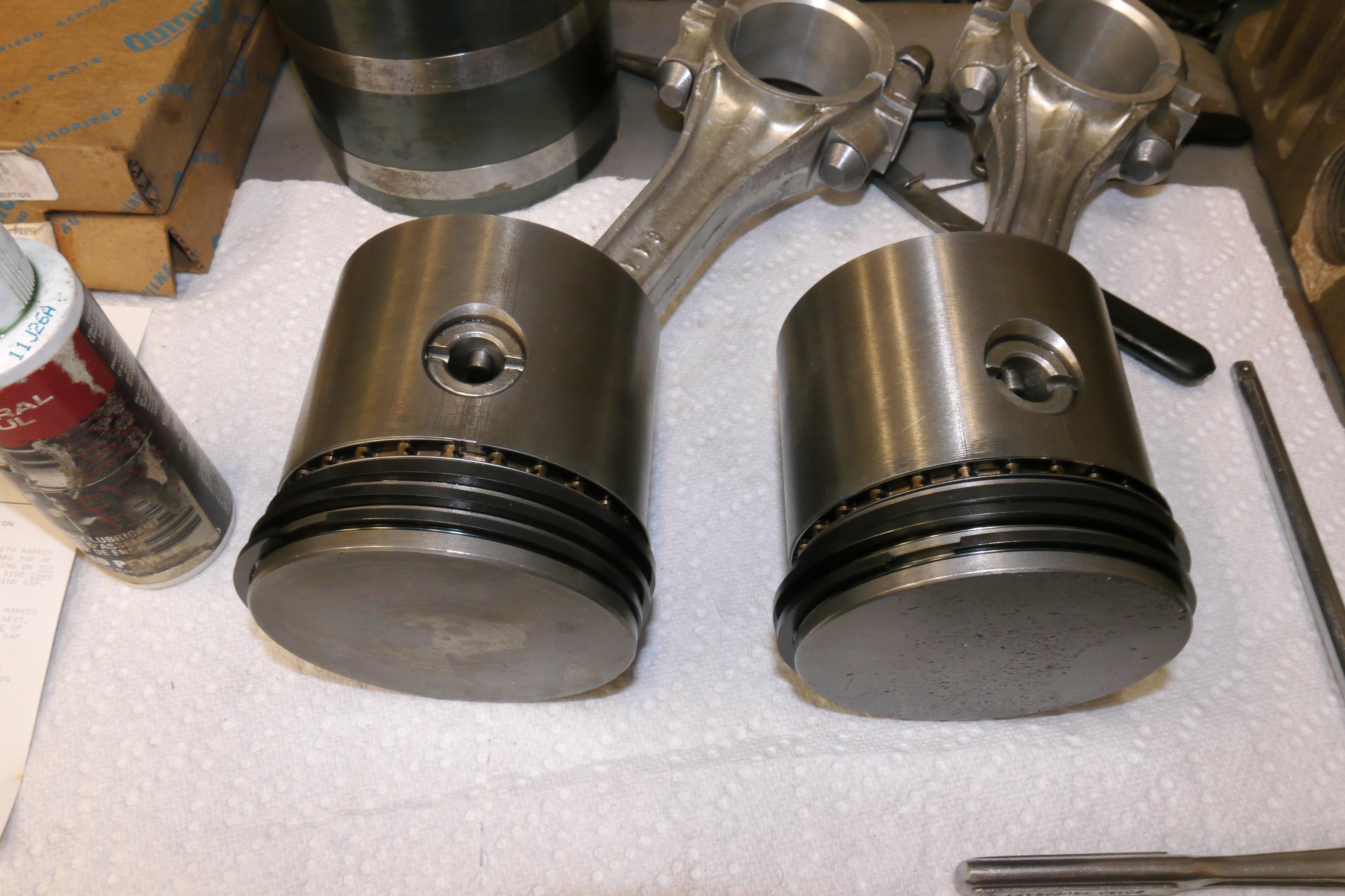
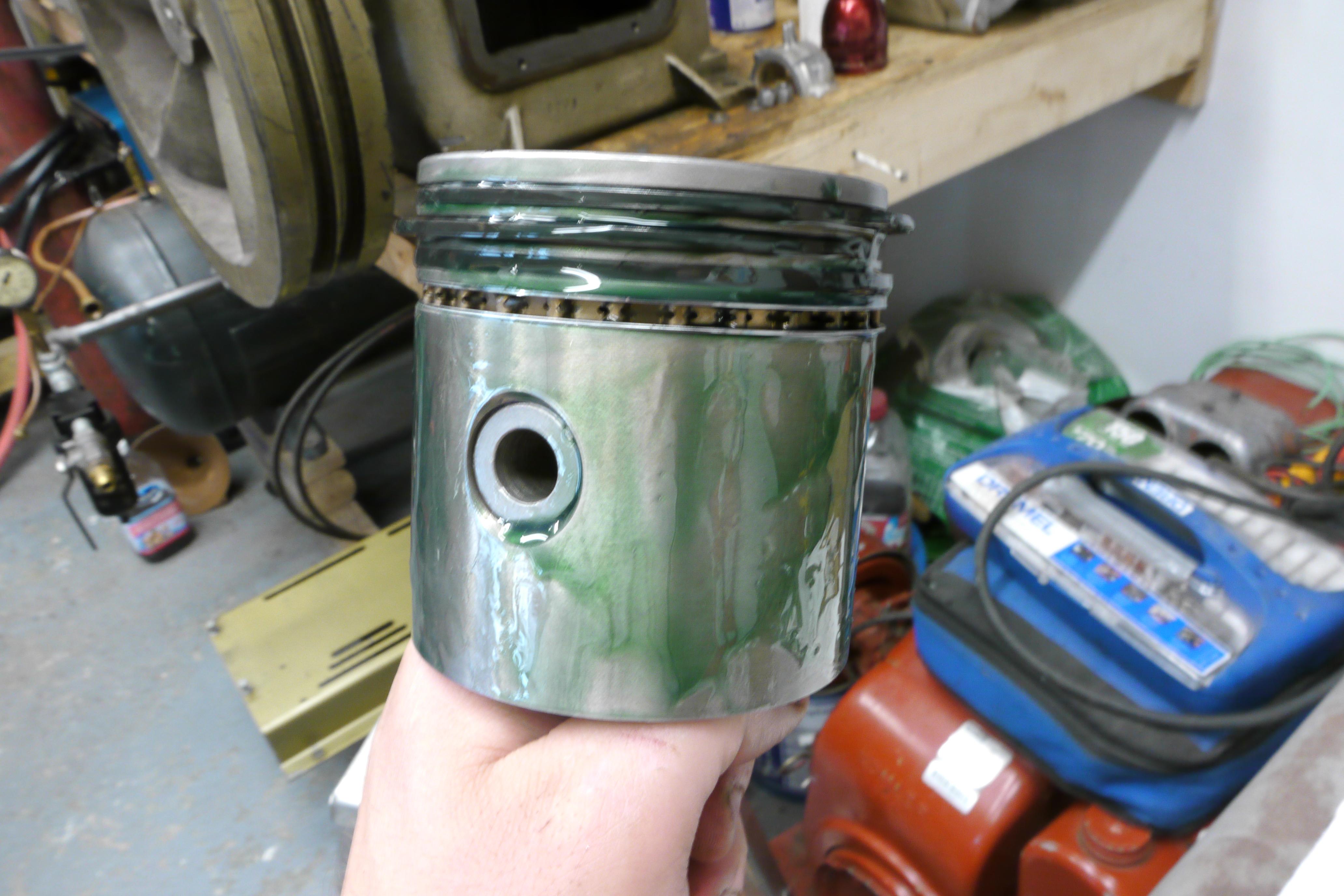
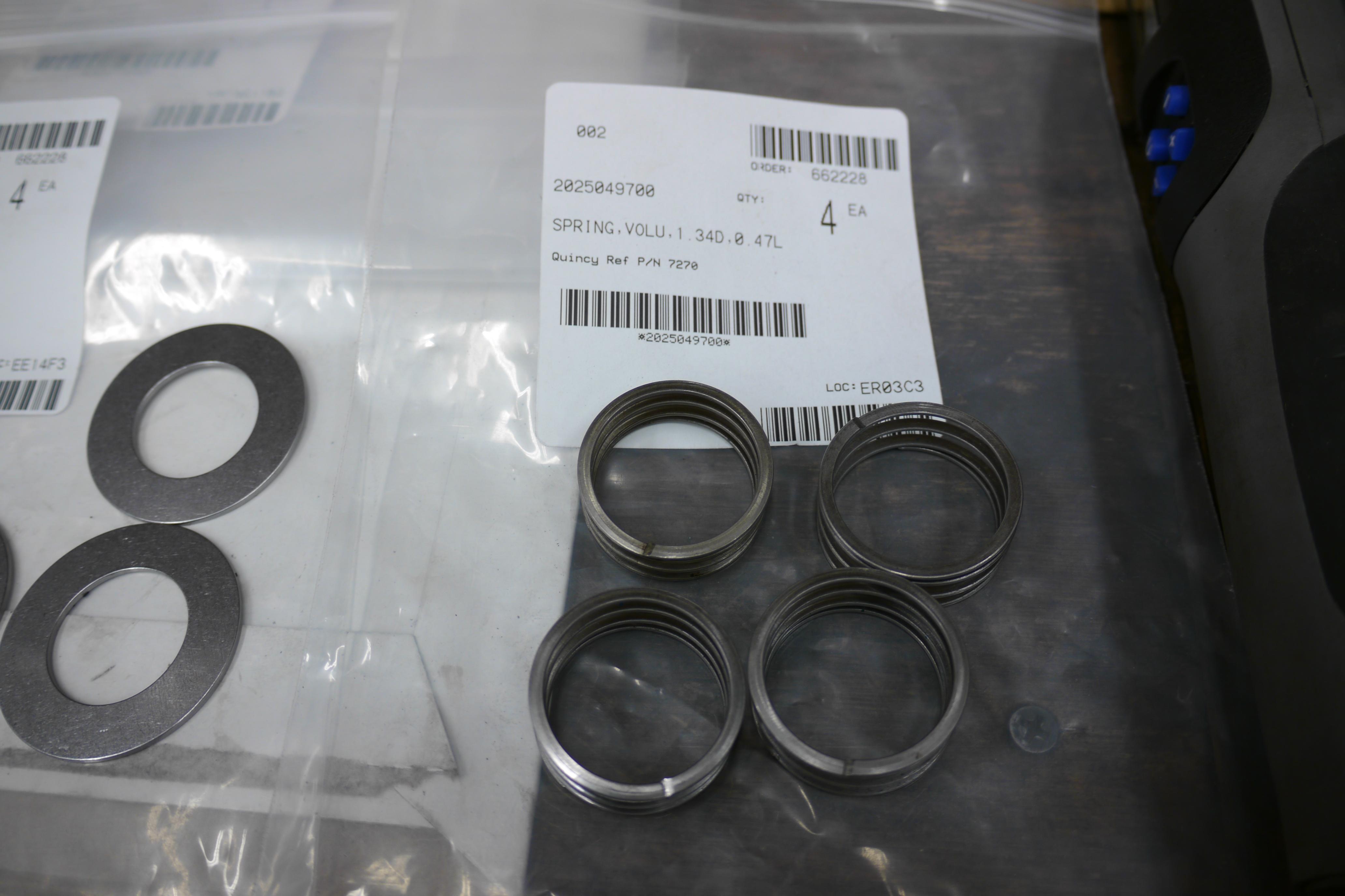
The pistons themselves looked good with exception of the crown on the rear piston. These pistons are cast steel and very heavy in all aspects. They have four ring grooves filled with eight rings. The upper two ring landings are each fit with a compression ring and a dished spring spacer, the third ring landing fit with a cast iron compression ring, and the lowest ring landing fit with two dished spring spacers and an oil expander. The additional dished spring spacers prevent the rings from turning in their bores, maintaining the stagger in the ring openings. This is a feature found in the legendary QR-25 series compressors, and is proven to help maintain consistent cylinder pressure over many thousands of hours of operation. Quincy also pins the wrist pin so that it cannot rotate in the bore of the piston. This forces the replaceable brass insert in the top of the connecting rod to handle all of the rotational stress. The connecting rods are heavy duty cast aluminum with replaceable copper jacketed bearings. Their is a hole drilled down the centerline of the connecting rod allowing pressurized oil to lubricate the small end connecting rod bearing. The replaceable copper jacketed large end rod bearings were in pretty decent shape considering how many hours were on this compressor. The silver bearing surface was only just starting to wear.
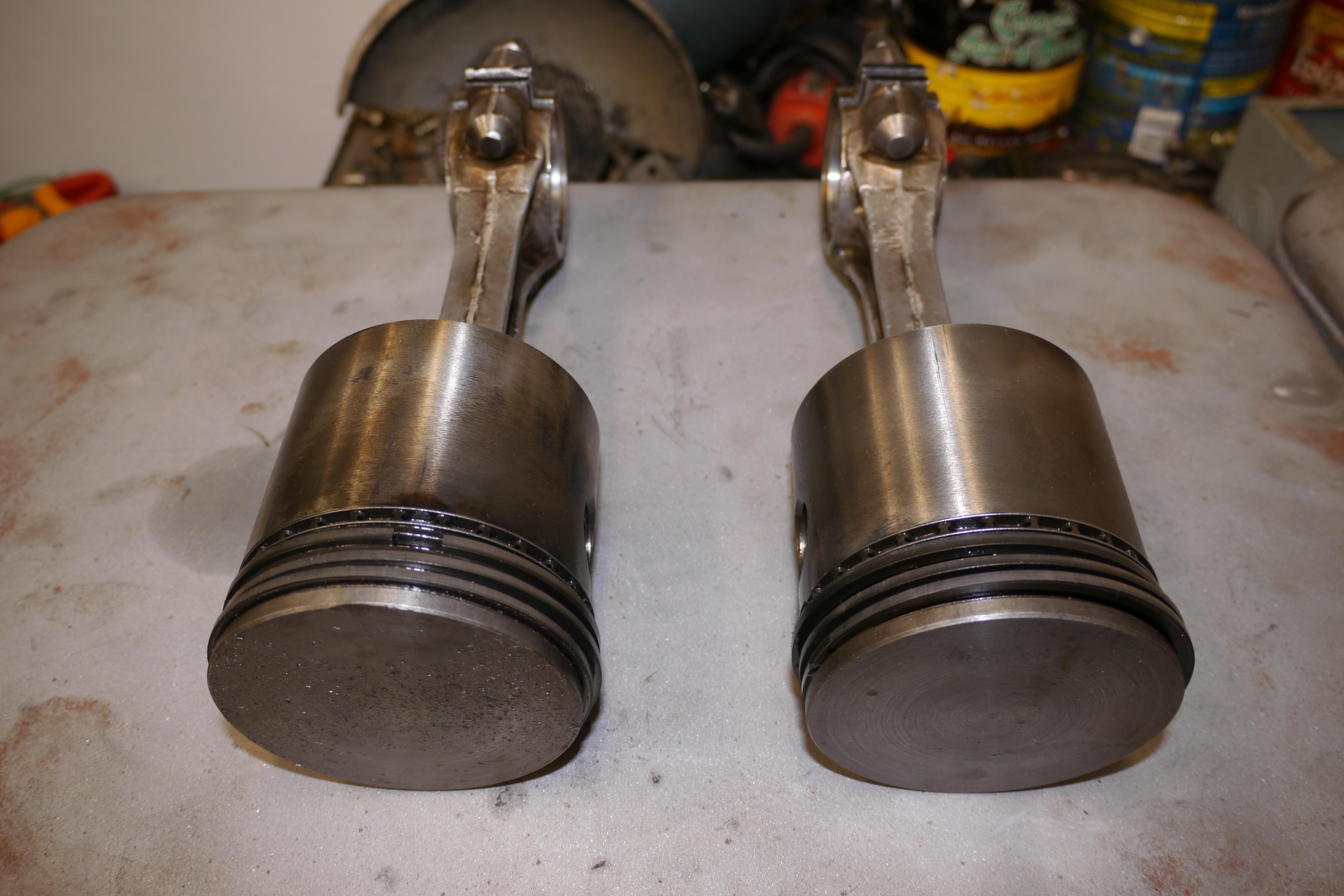

The rings were in pretty decent shape despite the compressor having been seized up at some point in time. The ring landings were in nice shape, no chips or cracks to be found. The oil control rings were still doing a decent job scraping the walls of the cylinder, judging by the lack of carbon buildup on the skirts. The piston skirts were in really nice shape, there was no major scoring at all.

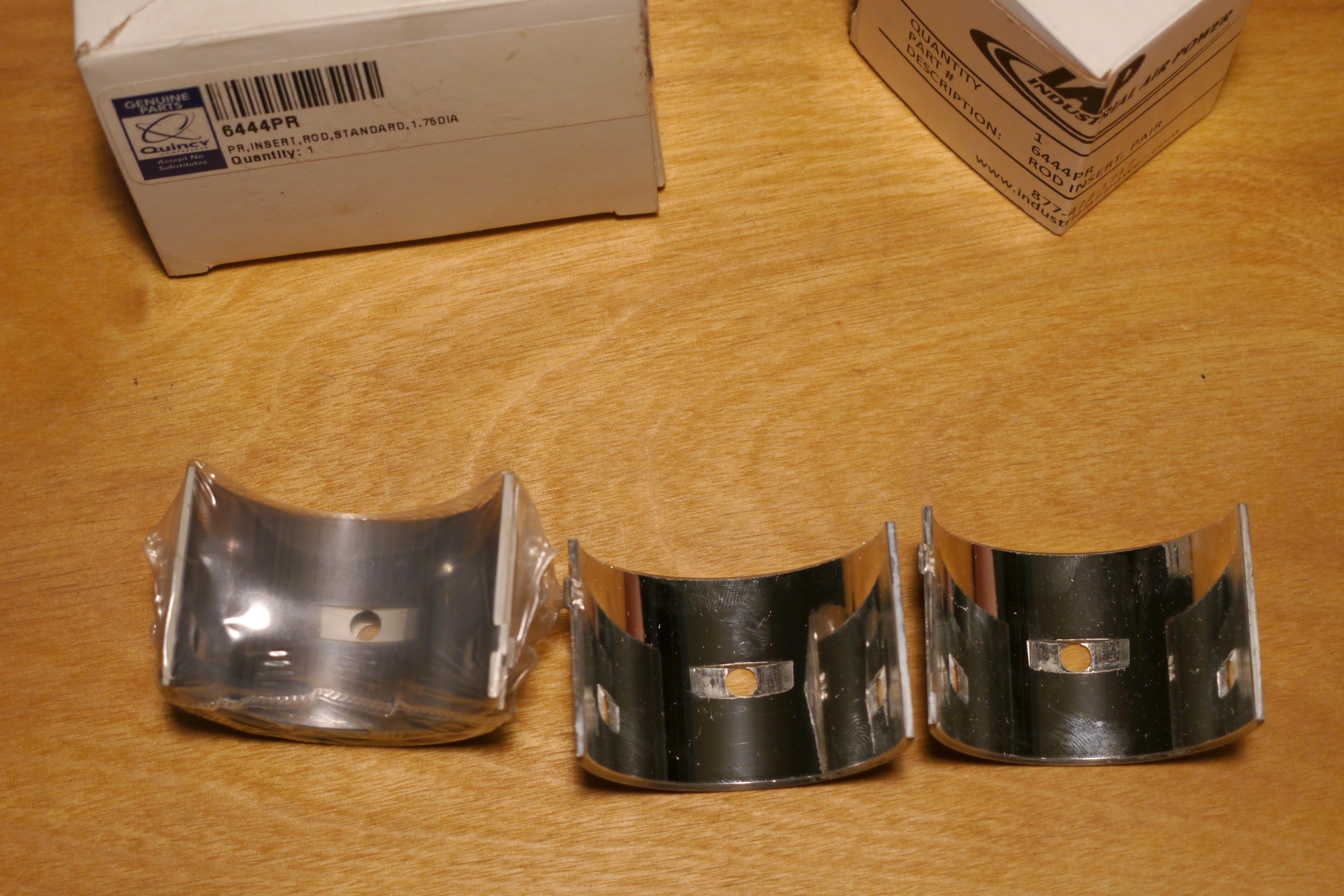
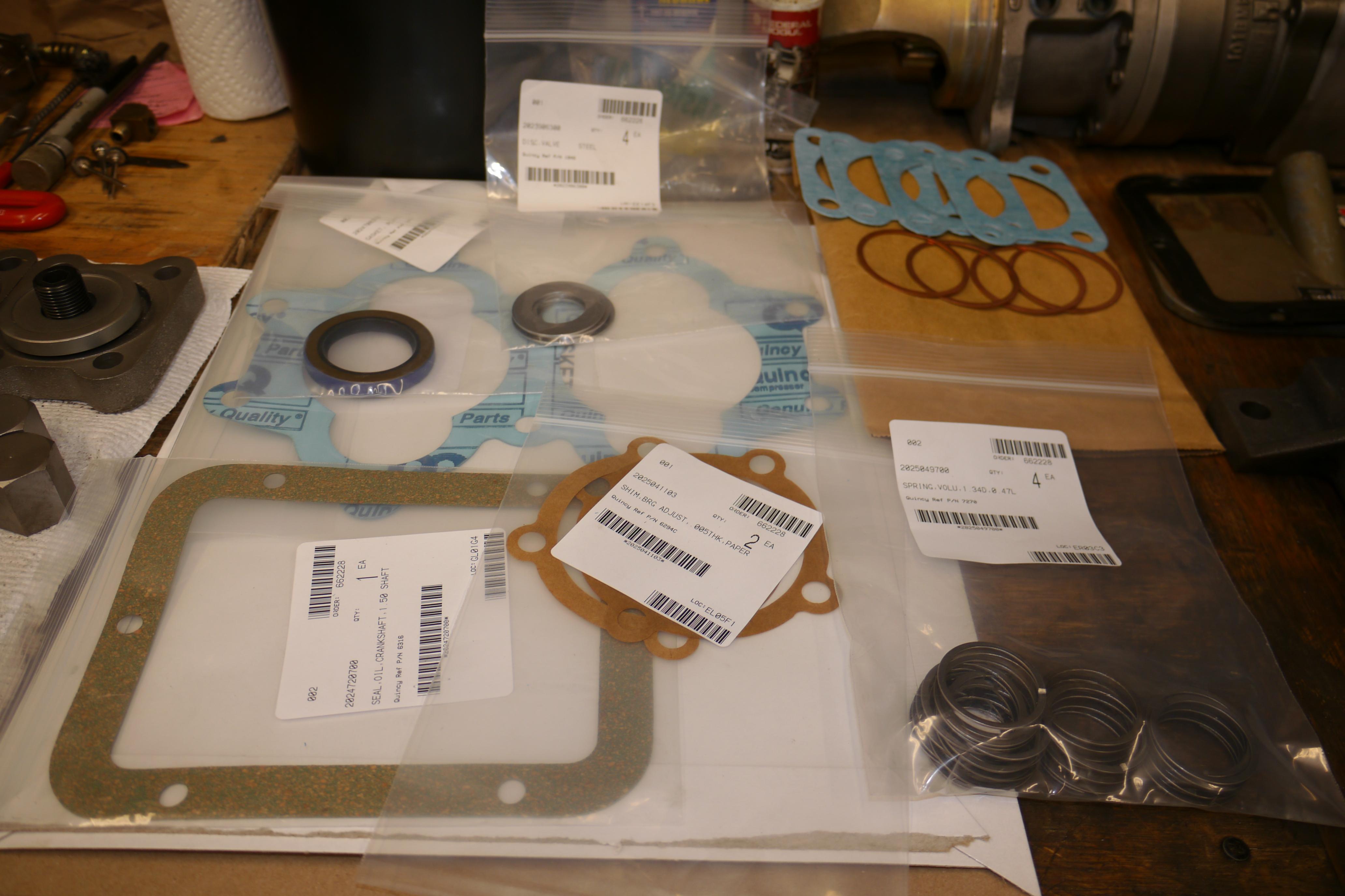
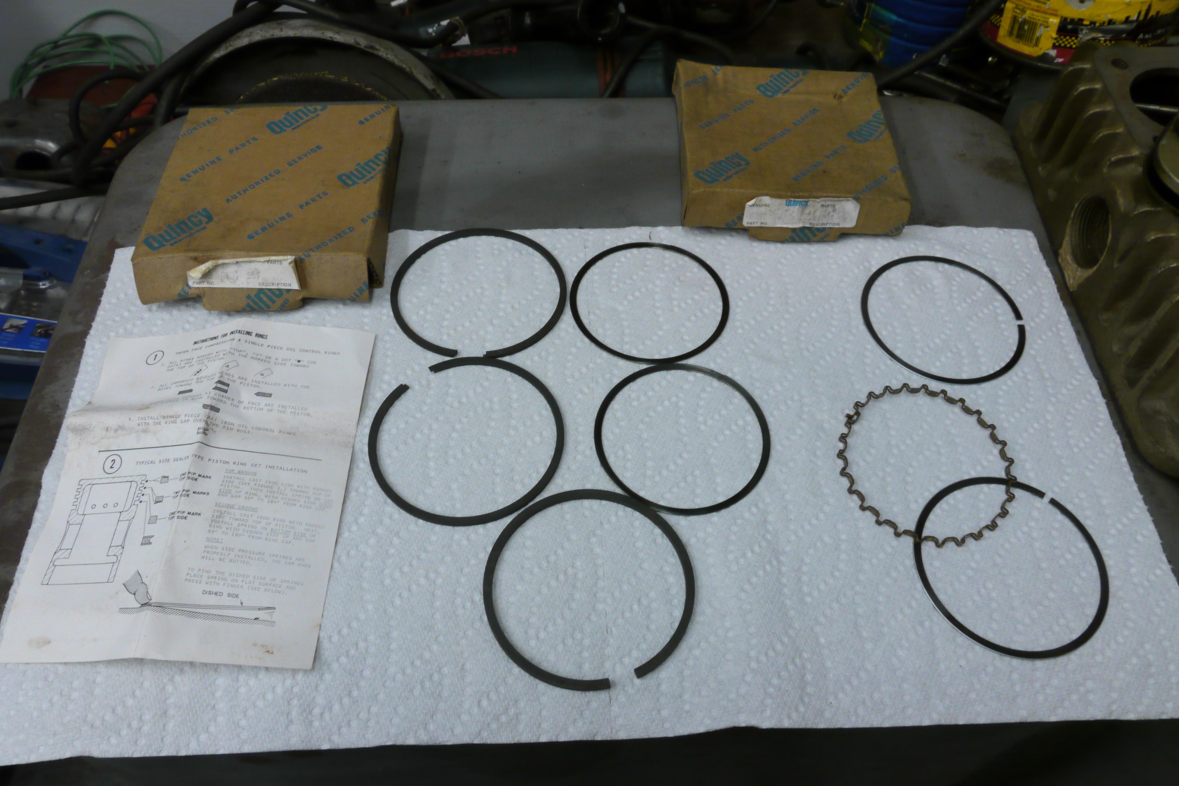
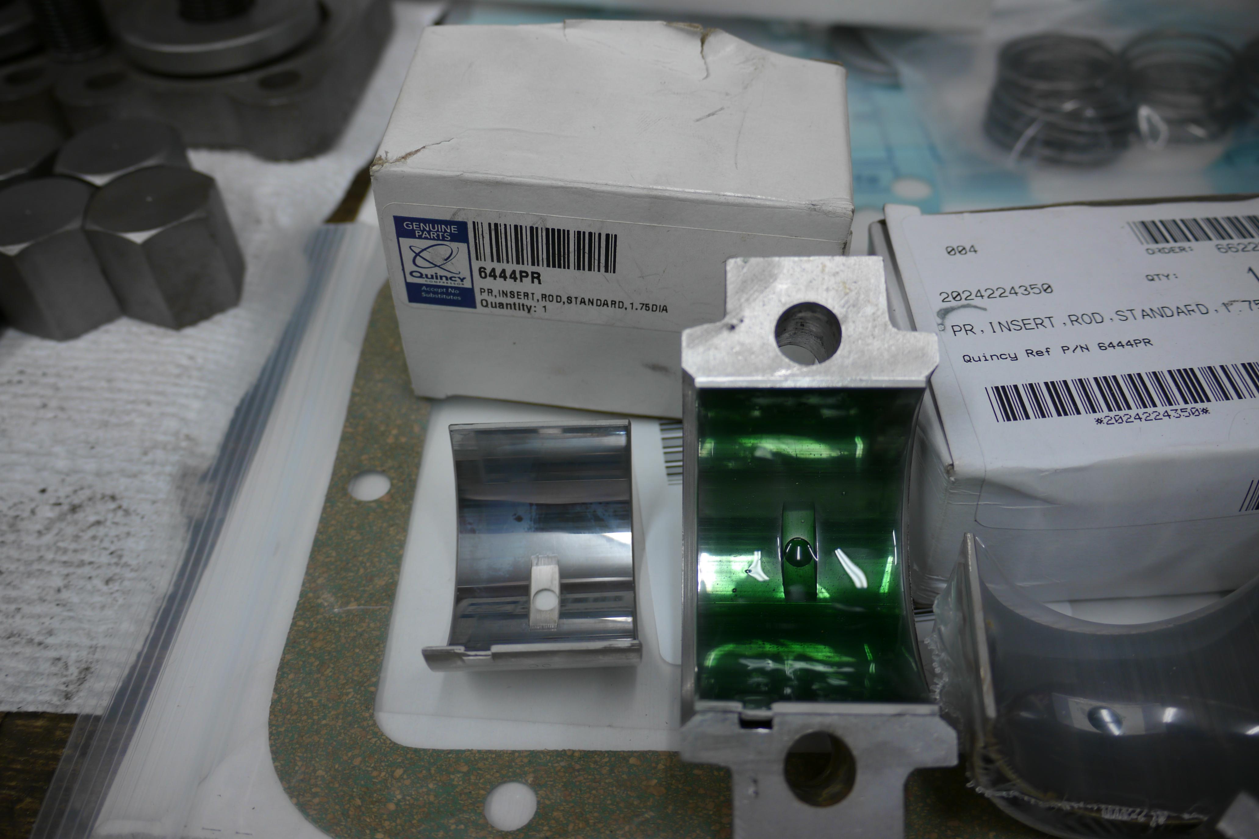
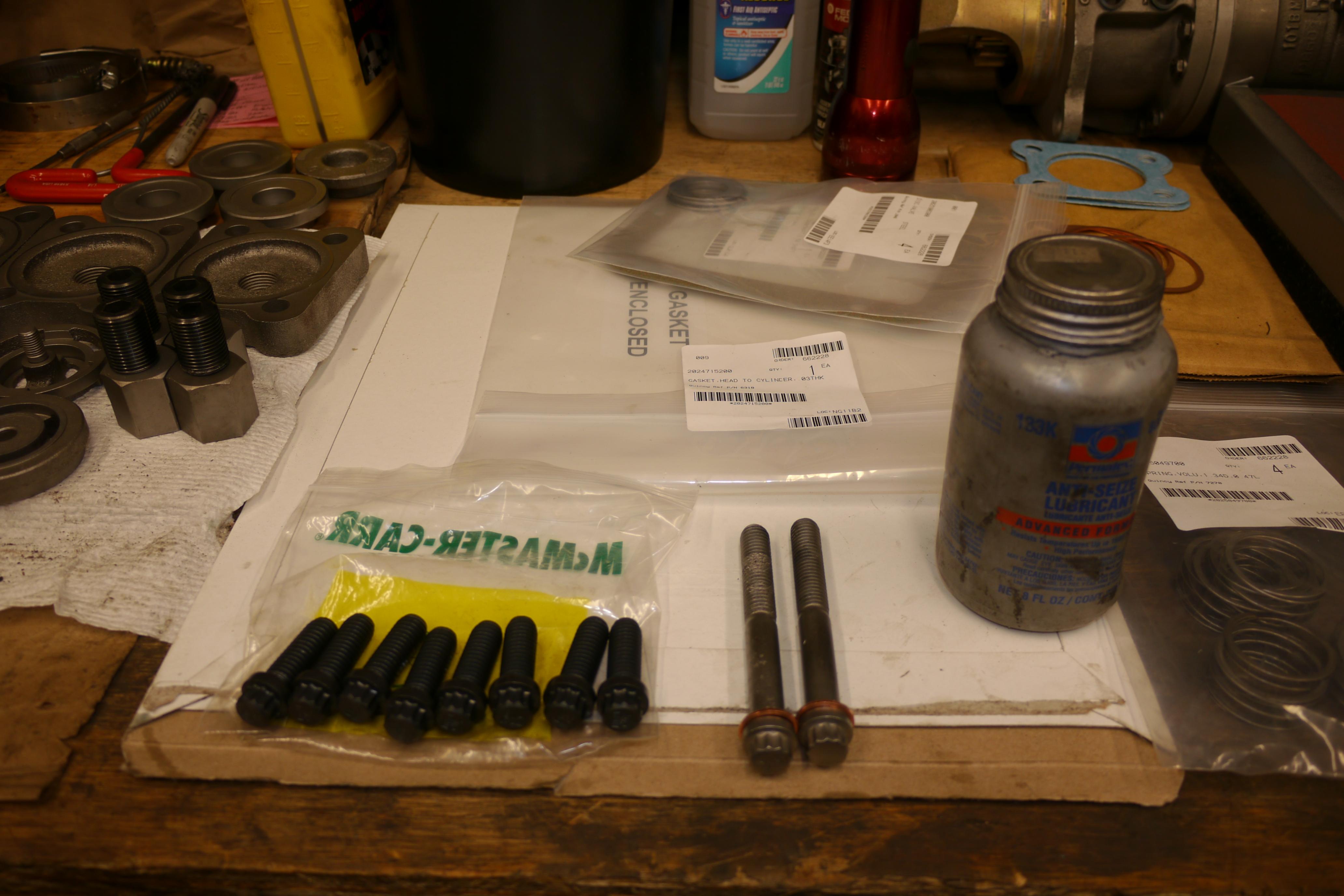
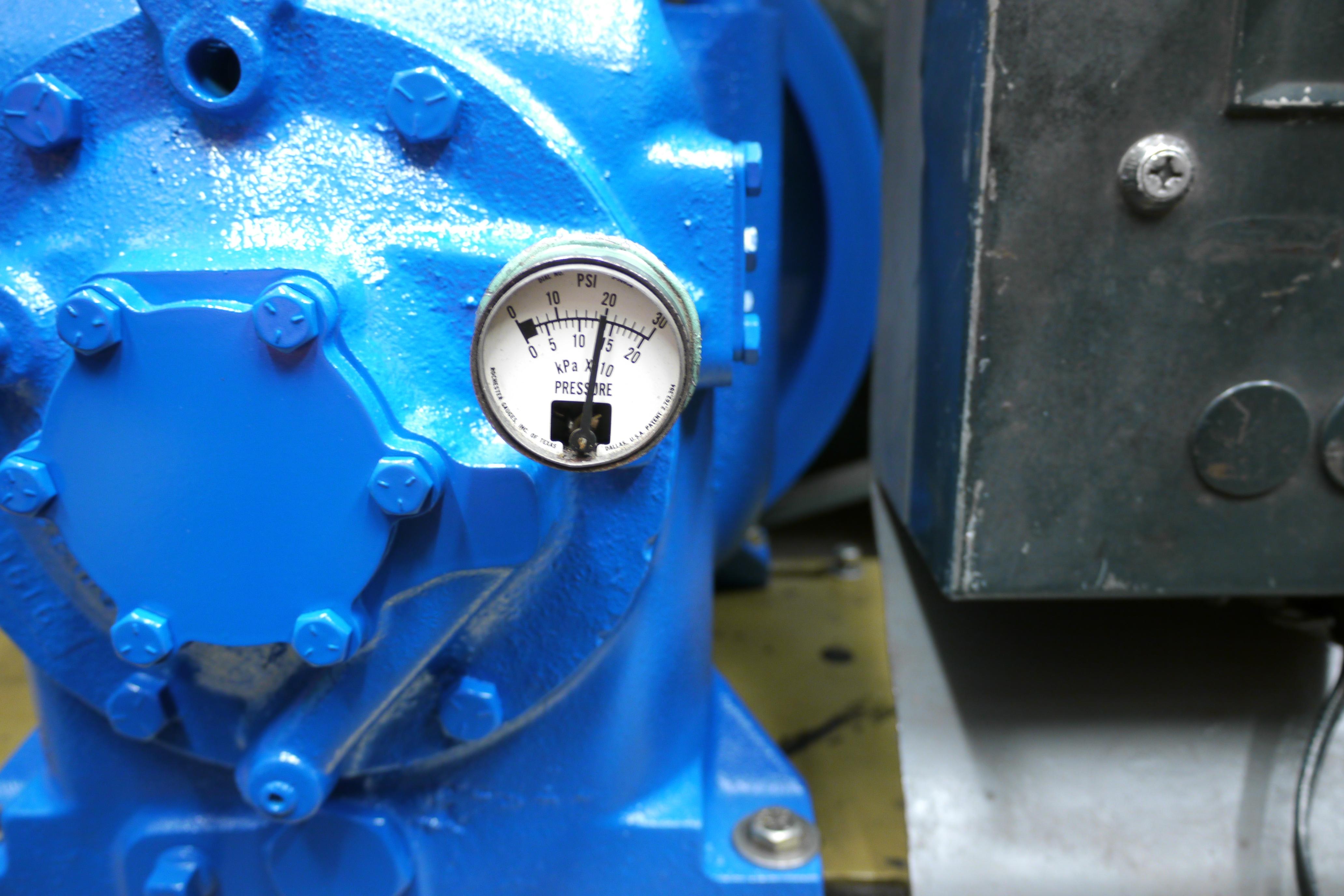
Thankfully Quincy Compressor Co. lists parts and service manuals for most of their compressors on their website. I was able to download a parts manual for my model 230-32 compressor as well as an updated parts manual dated 1988. I compiled a list of parts that I wanted to replace; piston, rings, connecting rod bearings, discharge valve bodies, discharge valve seats, intake valve bumpers, intake and discharge valve discs and springs, discharge valve spacers, gaskets for the entire compressor and a few replacement cylinder head bolts. At the time, I did not know of any compressor shops on Long Island. I had searched for all of these parts online from retailers such as ecompressedair, industrialairpower and ebay. I was able to find genuine piston rings and new oil pressure gauges on ebay, but the rest of the parts had to be found elsewhere. I found the remainder of the parts online from Industrial Air Power and proceeded to make an order through them. The purchase was made on 7/10/2015 and I did not receive any of the parts until 8/06/2015 nearly a full month after the order was placed. Not only did I have to wait a month to receive the parts that I ordered, but the parts which arrived were damaged! Half of my order vanished through the postal system because they packaged my parts in a used box without sealing the edges. The parts which did arrive were not the “genuine” parts that they listed on their website, but cheap aftermarket parts at full retail price. I was infuriated, emails and phone calls to the company went unanswered, and they were giving me the good old fashioned round around. I had to go through my credit card company to pressure Industrial Air Power to refund my account. I did not receive a refund until 8/21/2015. I posted my experience with Industrial Air Power on google reviews and the BBB, and almost a year later, in May of 2016 I received a letter from their attorney about my negative reviews of the company. They threatened me to the point that I had to pull my reviews. Talk about a company you want to do business with! It should be against the law to be able to buy your way out of criminal acts.
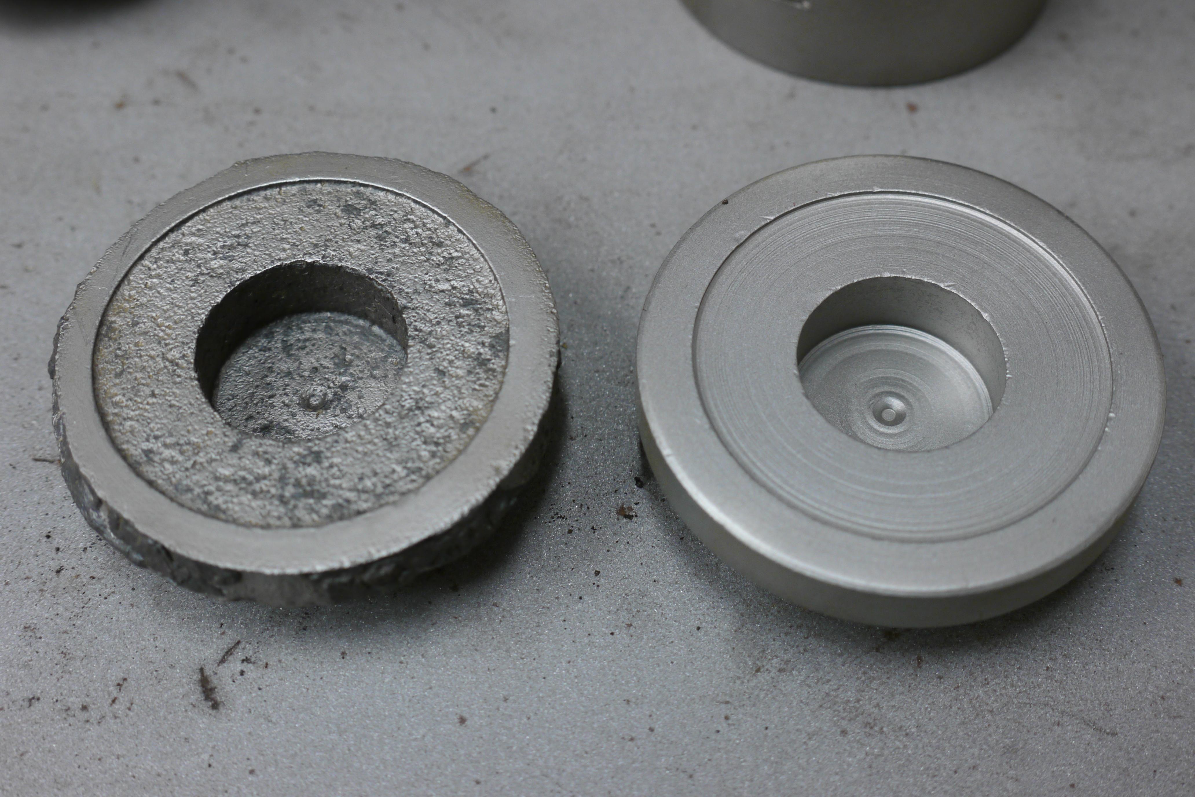
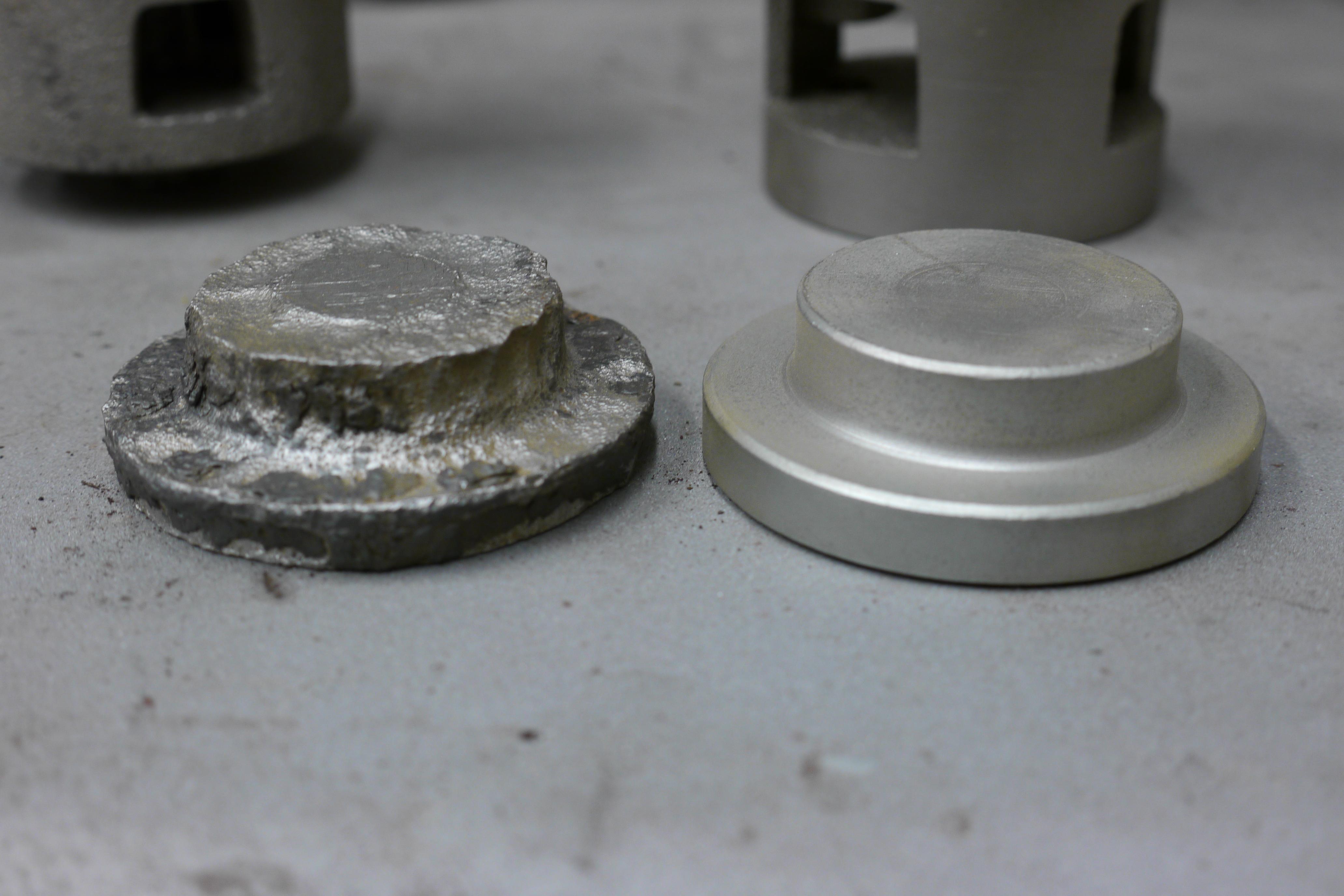
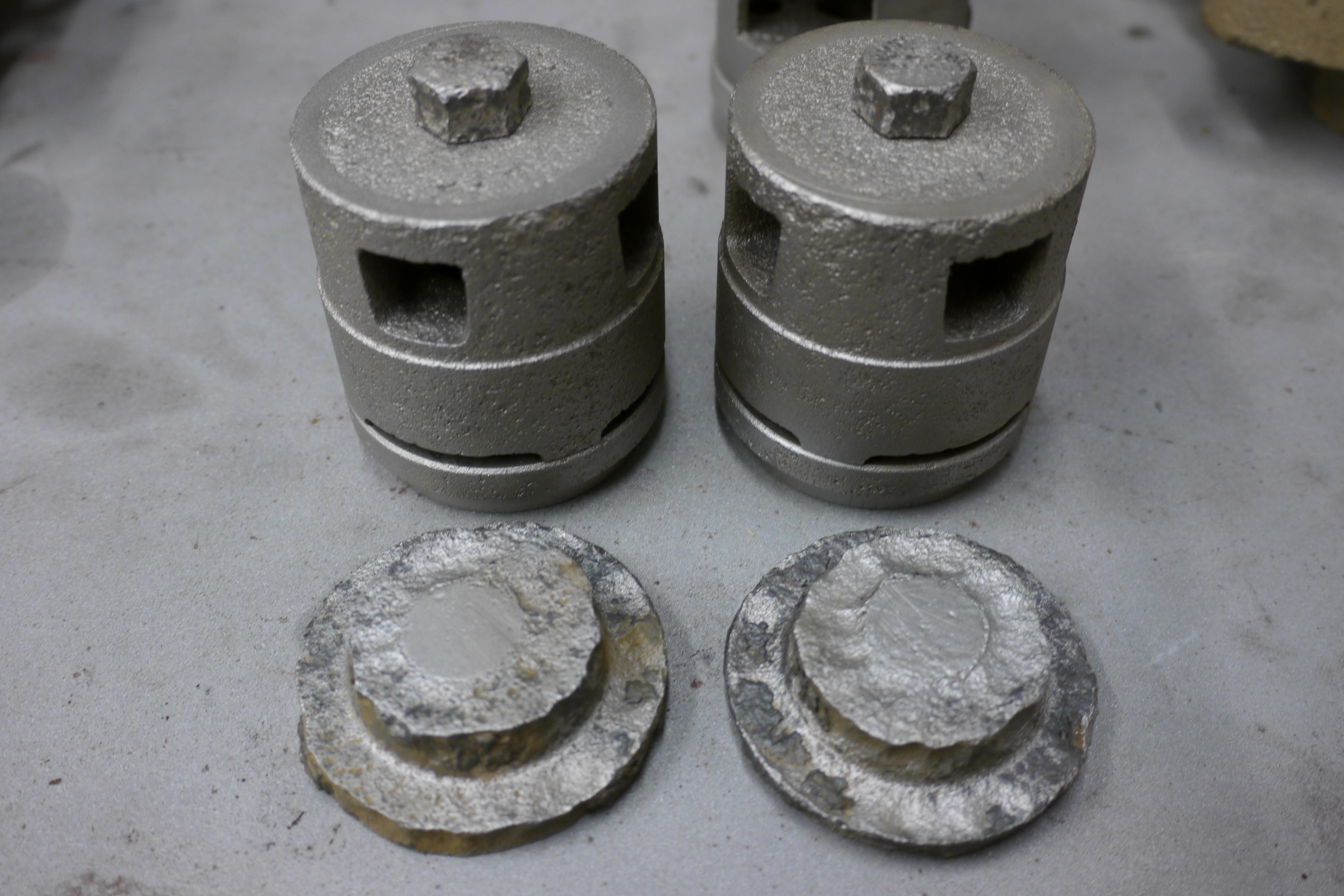
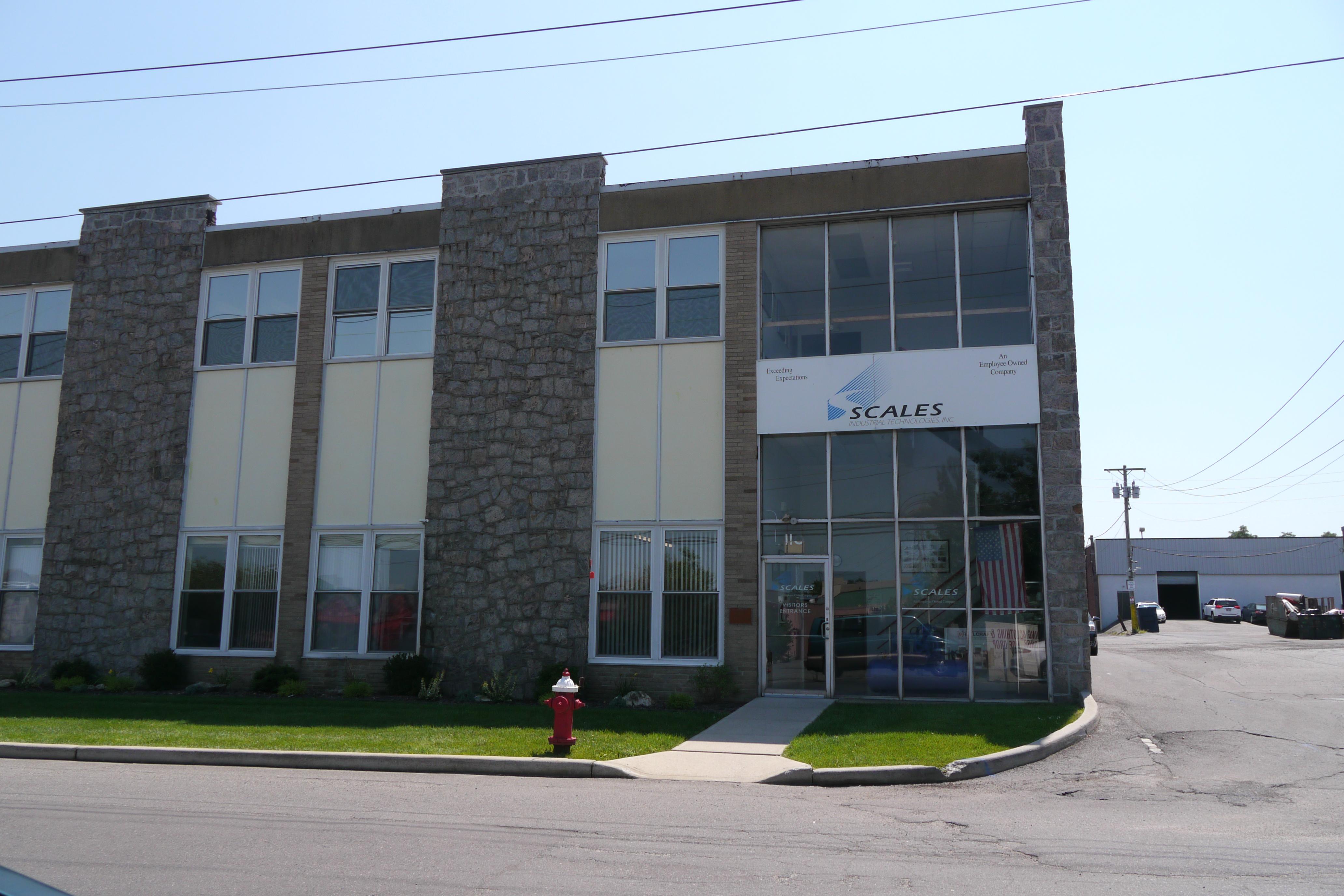
Needlesstosay the story ends well. The day after my “genuine” parts arrived from Industrial Air Power I took a day off from work and headed over to Carle Place, home of Scales Compressor, the only Quincy dealer in my area. I brought the parts I received from Industrial Air Power and the story that went along with them. I did not know anyone at Scales Compressor, and they treated me as if I was a regular customer. Mike Engesser in the parts department and his mechanic Cesar were absolutely wonderful to work with. Within just a few minutes they collected all of the parts I was lookin for from their well stocked warehouse. Every part was placed on the sales counter in genuine Quincy packaging. As this was my visit to Scales compressor, I brought along some of my used compressor parts, where I received expert advice on the condition and reconditioning of my parts, as well as better used parts for rebuilding. At the end of the day, I walked out with more genuine Quincy compressor parts than I ordered from Industrial Air Power, including $94 worth of paint, and countless other used parts that they threw in, for less money than the cheap aftermarket parts that I received from Industrial Air Power!!! I took several good pictures of the "genuine" Quincy parts from IAP, and the actual genuine parts from Quincy. There is just no comparison at all. I returned the few parts that I bought from IAP and proceeded to rebuild my Quincy compressor with 100% genuine parts from Scales Compressor.

I media blasted the "new" used discharge valve bodies, spacers and bumpers that Cesar had given me, and prepared all of the prts for reassembly and rebuild.
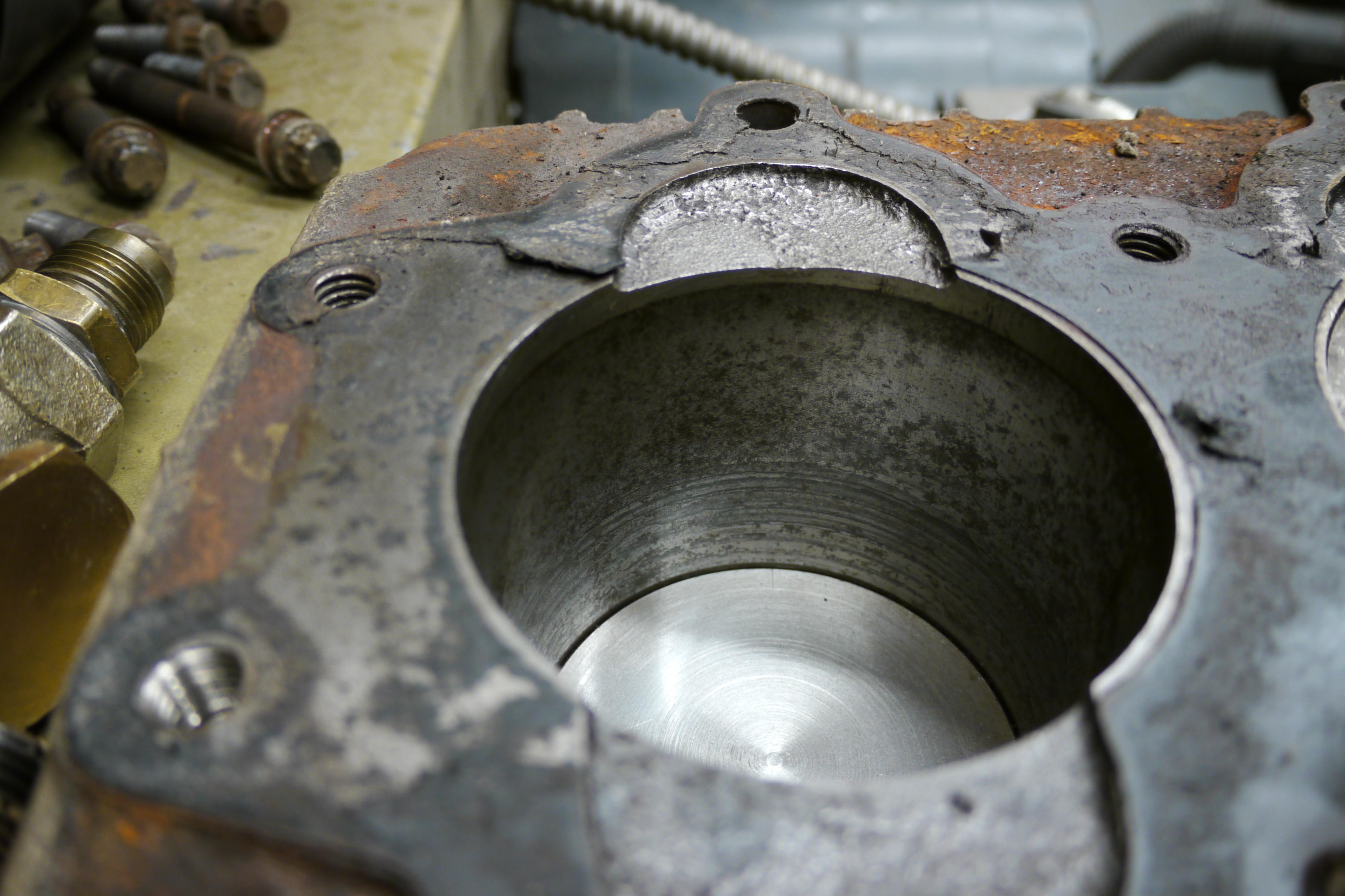
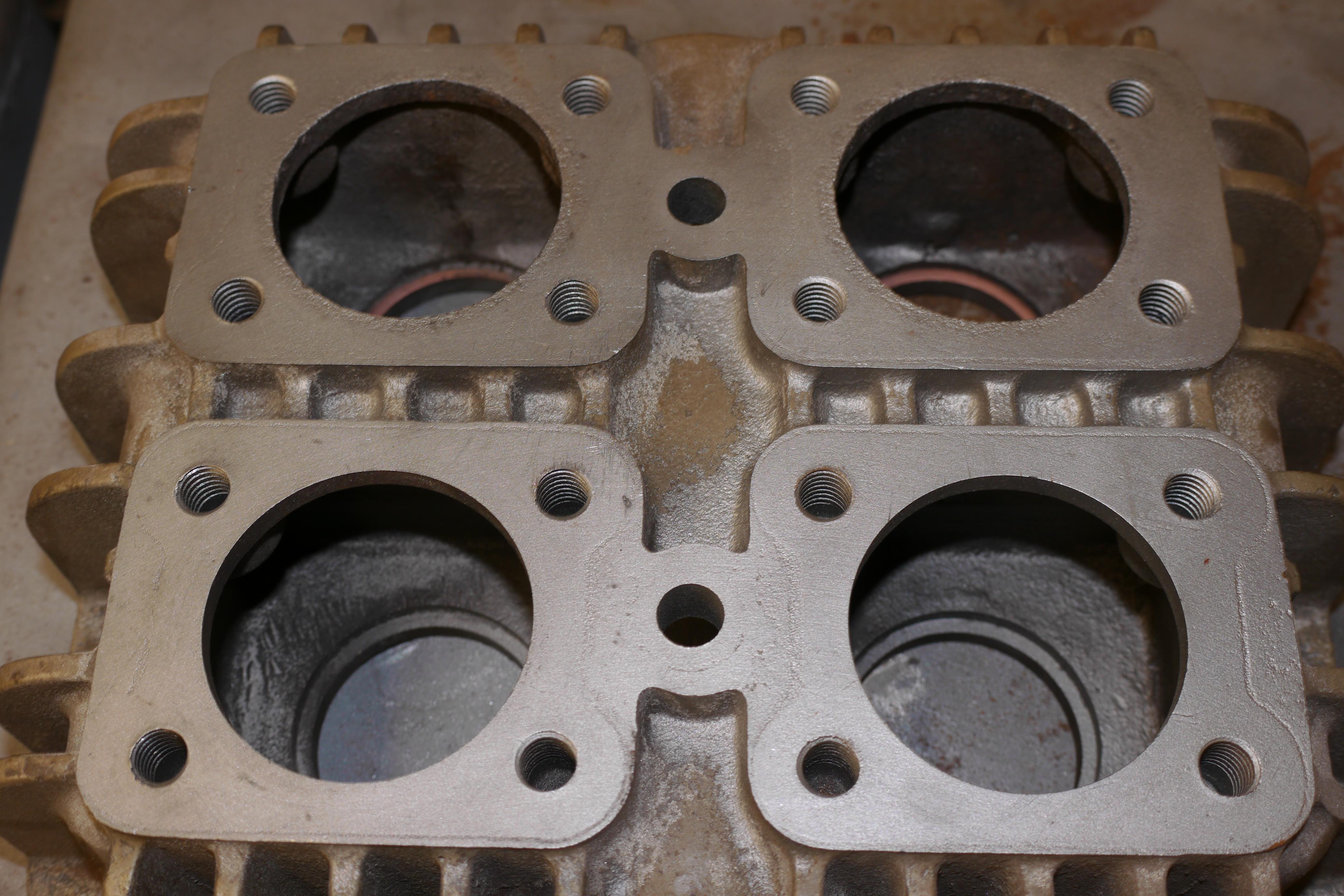
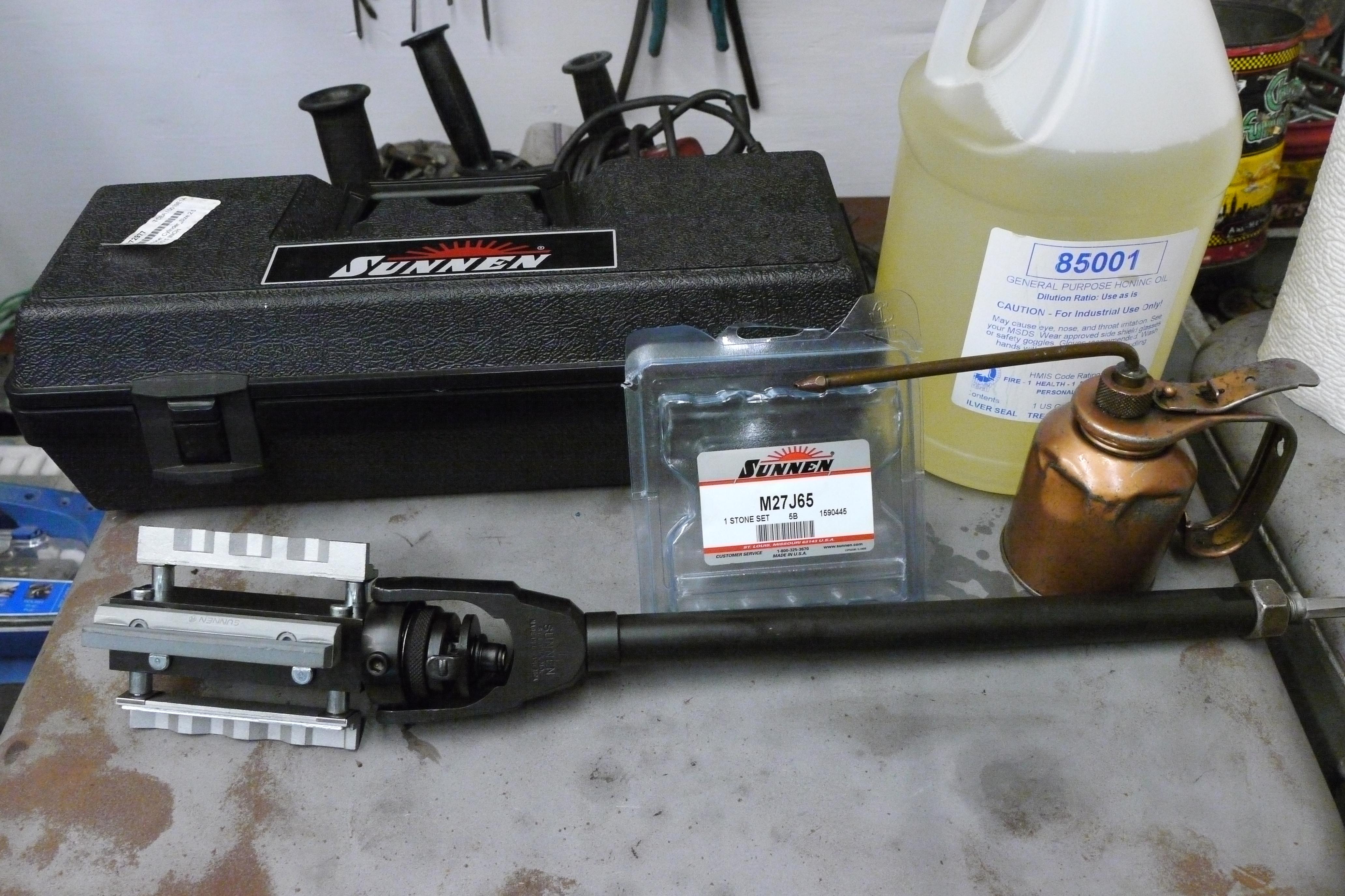
Cesar & Mike had convinced me that I could re-use the original pistons in my compressor as long as the piston to cylinder clearance was within spec. Quincy lists the bore for this compressor as 3.5000-3.5005" with an allowable piston to cylinder clearance of 0.003" on the bottom of the piston skirt. In order to get an accurate measurement, I had to lightly hone the cylinder. I assembled my Sunnen AN-815 rigid body expanding mandrel hone with 280 grit silicon carbide stones and set my drill to the appropriate honing speed of 375rpm. After honing the cylinder to break the glaze and remove the surface rust, I was able to check piston to cylinder clearance with a set of feeler gauges. After taking some measurements, I contined to hone the cylinder until just about all of the surface errata had been removed. I ended up with a piston to cylinder clearance of 0.005" on the bottom of the piston skirt, exceeding the higher end of what Quincy recommended, but still less than what would justify boring the cylinders oversize. Once both of the cylinders measured out the same, I spent quite a bit of time cleaning the cylinders and the inside of the crankcase. Particles from the honing stones and the cast iron removed from the cylinder are abrasive and need to be completely removed before rebuilding the compressor.
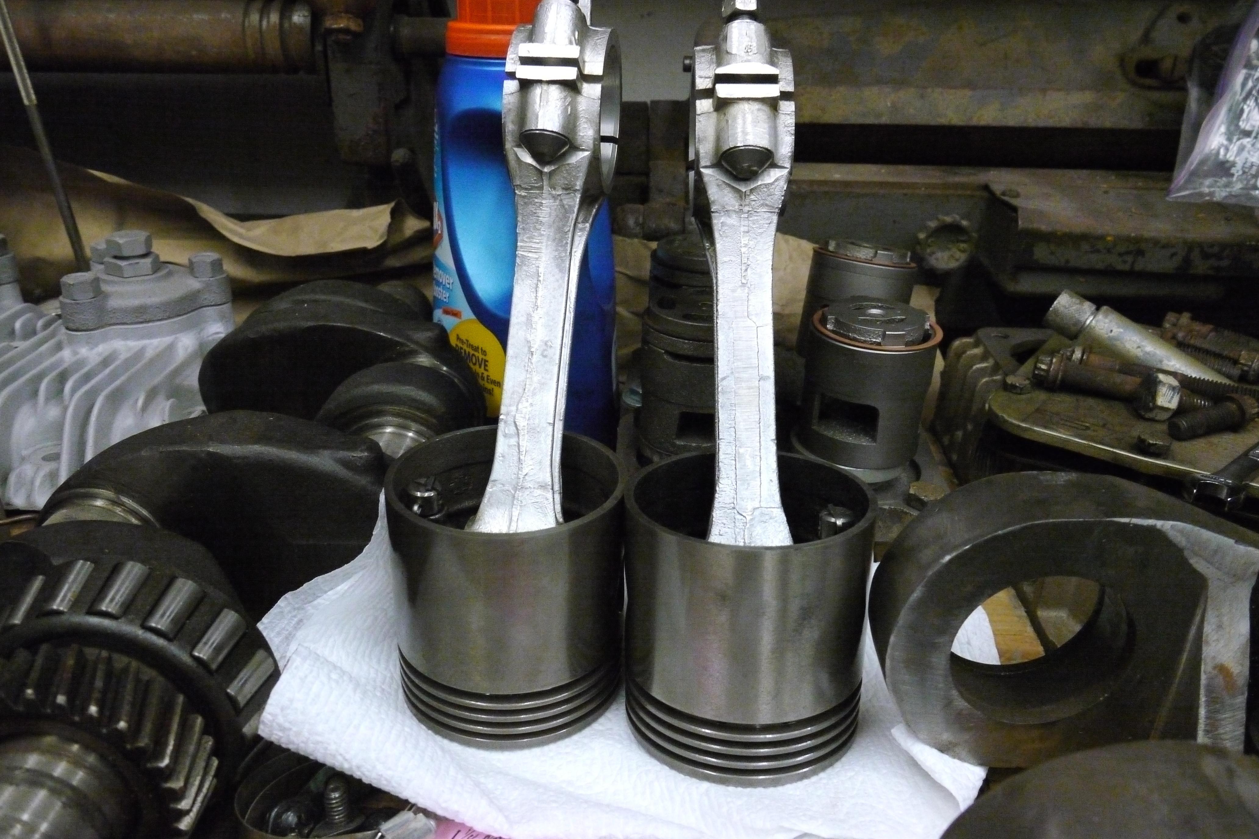
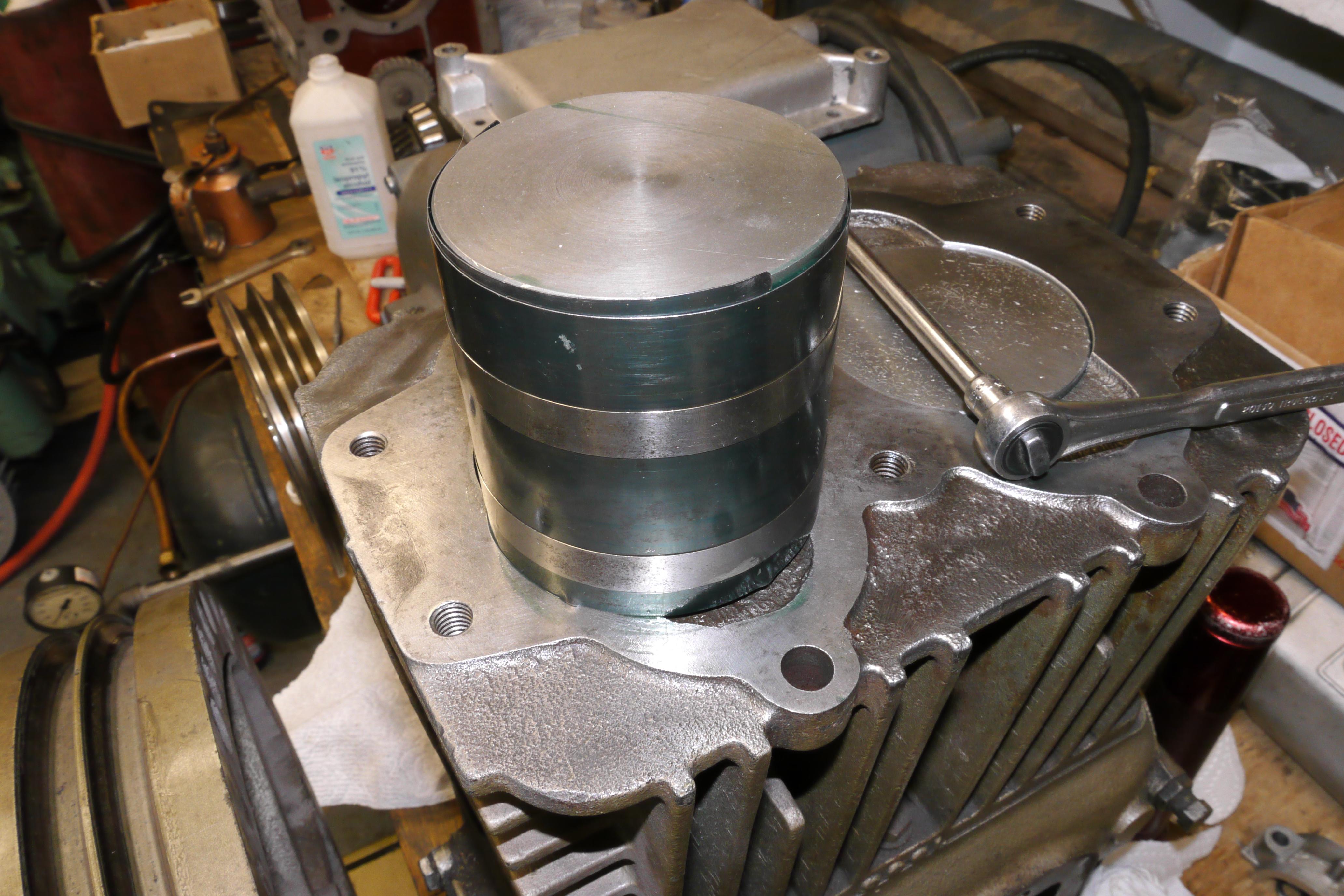
With a handheld piston ring expander, I loaded the pistons with new rings. Quincy provides a little pamphlet on how to properly install piston rings, since every compression ring has a spring loaded expander to keep the ring from turning in the bore. You might ask how I was able to clean the old original pistons up so nice. I had let them sit in my ultrasonic cleaner for quite some time to purge all of the pores from dirt and rust. Once both of the pistons were assembled, I liberally coated each of the piston skirts with assembly lube. With a ring compressor and a rubber mallet I was able to load both of the assembled pistons into the crankcase.
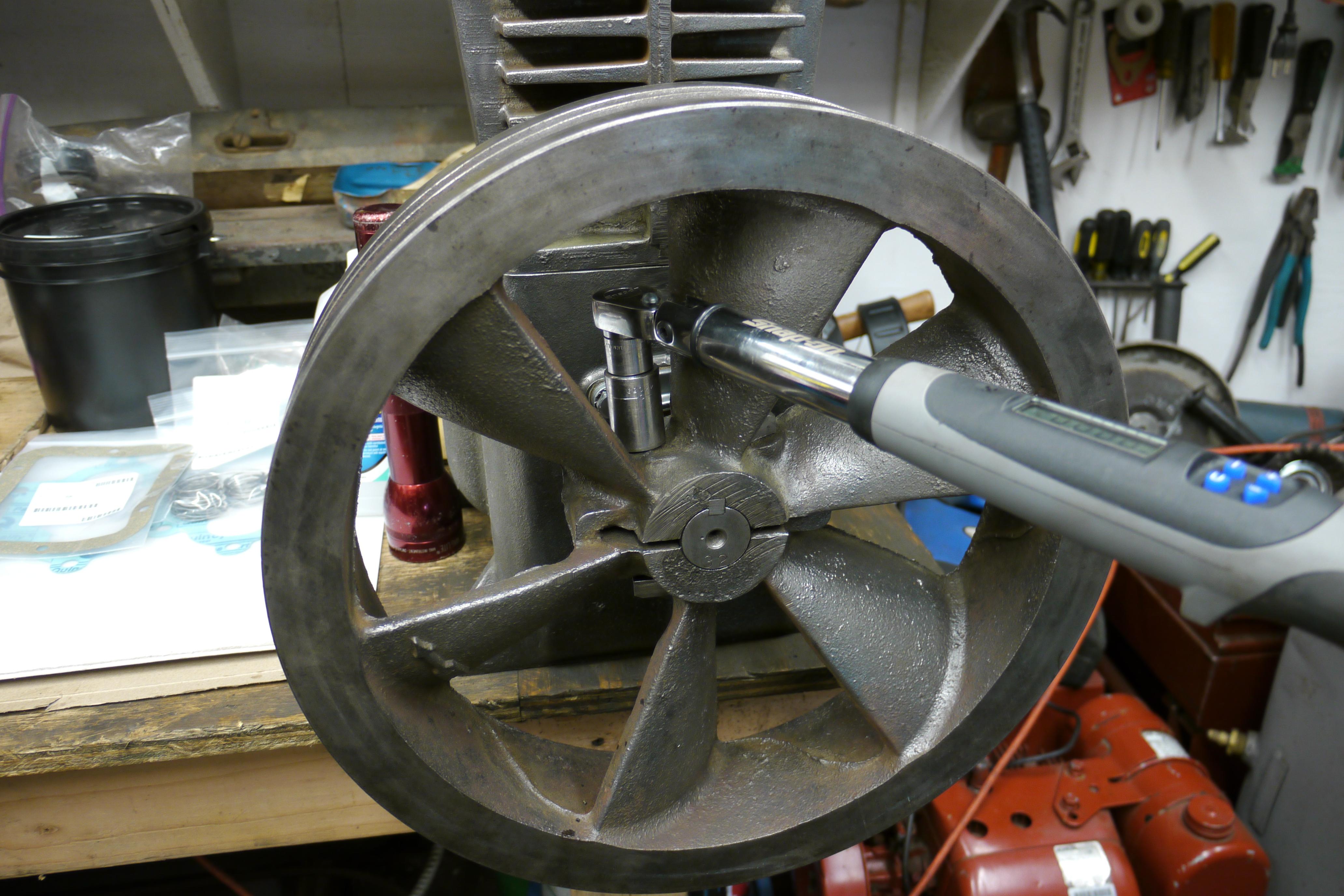
With both of the pistons installed, it was time to fit the new copper jacketed replaceable connecting rod bearing inserts. I liberally coated each of the bearing inserts, wiped the crankpin down with a microfiber cloth to enure all debris are absent from the surface, and proceeded to assembly. It is critical to have the pistons and connecting rods in the correct order. The connecting rods and caps are line bored after being cast, so it is critical that they line up properly. Once everything is assembled, it is than critical to torque the connecting rod nuts sufficiently. Only then can the crankcase inspection cover be mounted.

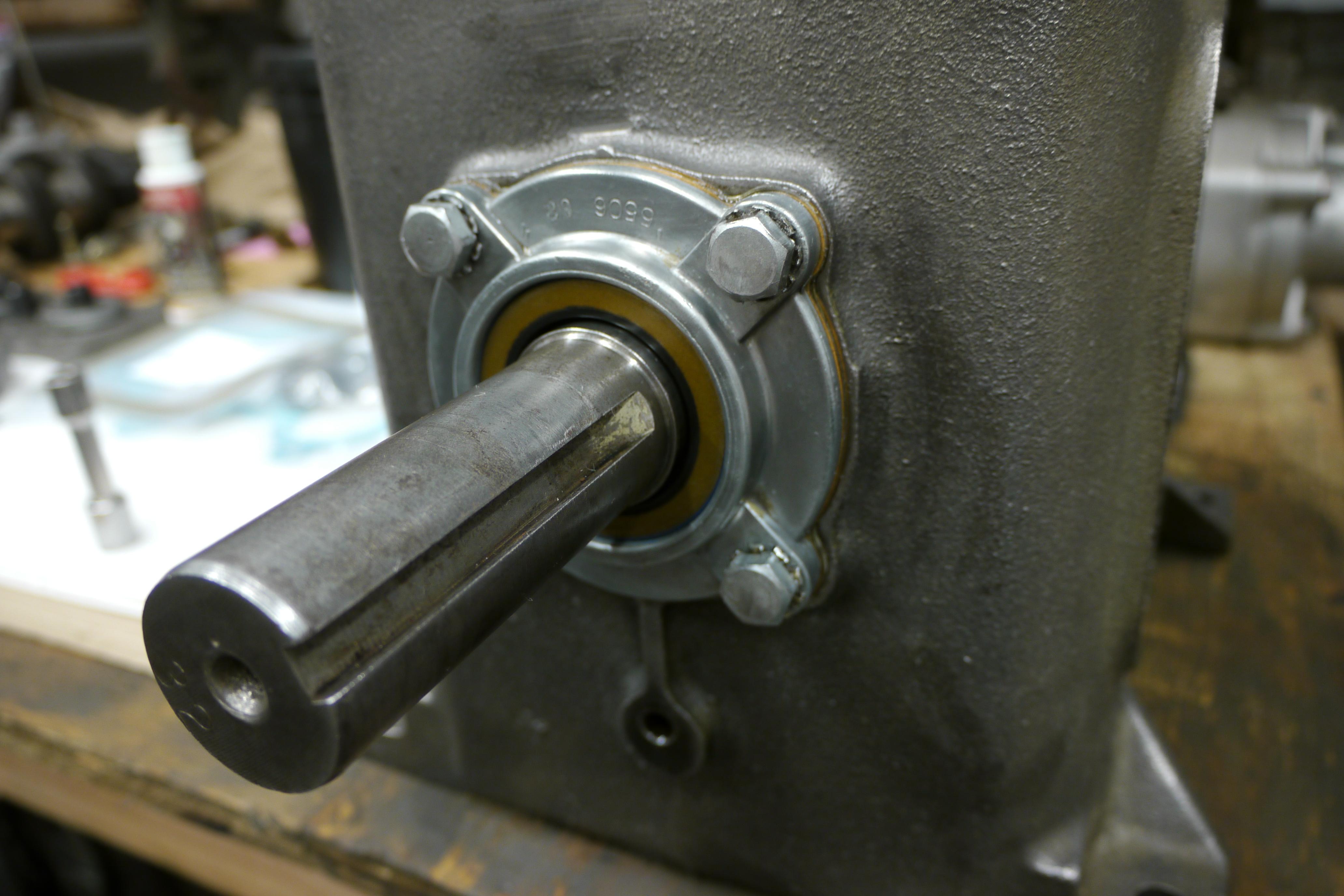
I took this opportunity to replace the front crank seal on this compressor. The original seal was not leaking, but it is the right time to change the seal since it is not exactly easy to pull the flywheel from the compressor. I replaced the front crank seal and its associative gaskets. I measured the thickness of the new gaskets in relation to the gaskets that were being replaced since the amount and thickness of these gaskets changes the end play on the crankshaft. Once installed, I was able to fit the flywheel back onto the crankshaft. You will notice the number "32" stamped into the end of the crankshaft. This is the ROC (Record Of Change) of the compressor. This will date the compressor and tell what changes were made up until this point of manufacture.

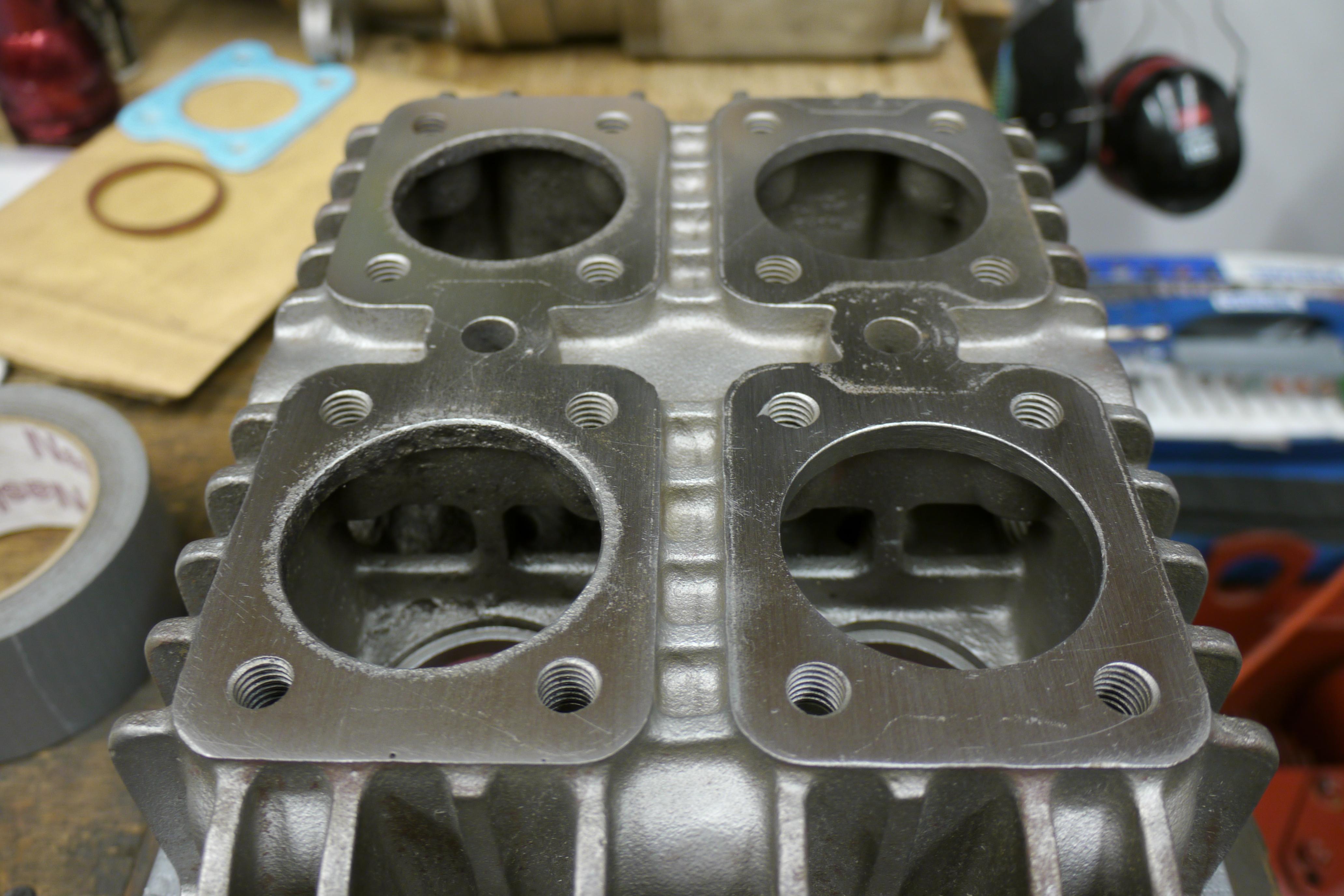
Now that the bottom of the compressor is all buttoned up, it was time to address the cylinder head. If you remember, the cylinder head was quite pitted above the rear cylinder where a valve disc had failed and broke into pieces damaging the head and the piston. Short of having the head flycut smooth again at a machine shop, I decided to use a piece of sandpaper on a granite surface block to clean up the jagged surface on the underside of the cylinder head. The goal was to simply remove the high points and give the bottom surface an overall smooth finish. Once satisfied, I flipped the head over and lightly sanded down the top of the cylinder head where the valve covers bolt to.

Before I bolt the cylinder head in place, I took Mike's suggestion to run the compressor for 24 hours without the head in place. At a moderate speed of 550rpm, keep note of how much oil is pooling on the top of the pistons. When oil ceases to pool on top of the pistons, the rings have seated and the compressor can be completely assembled and used as intended. To my surprise oil ceased pooling ontop of the pistons after just an hour and a half of runtime. I continued to run the compressor for another eight hours to be sure that the rings were seated and the reciprocating part of the compressor was operating properly. After the compressor cooled down, I went ahead and fit a new genuine Quincy head gasket. The head gasket is installed dry. The cylinder head is then aligned and torqued in place by central and perimeter bolts. Since they were so hard to remove, I coated the threads with anti-seize lubricant.
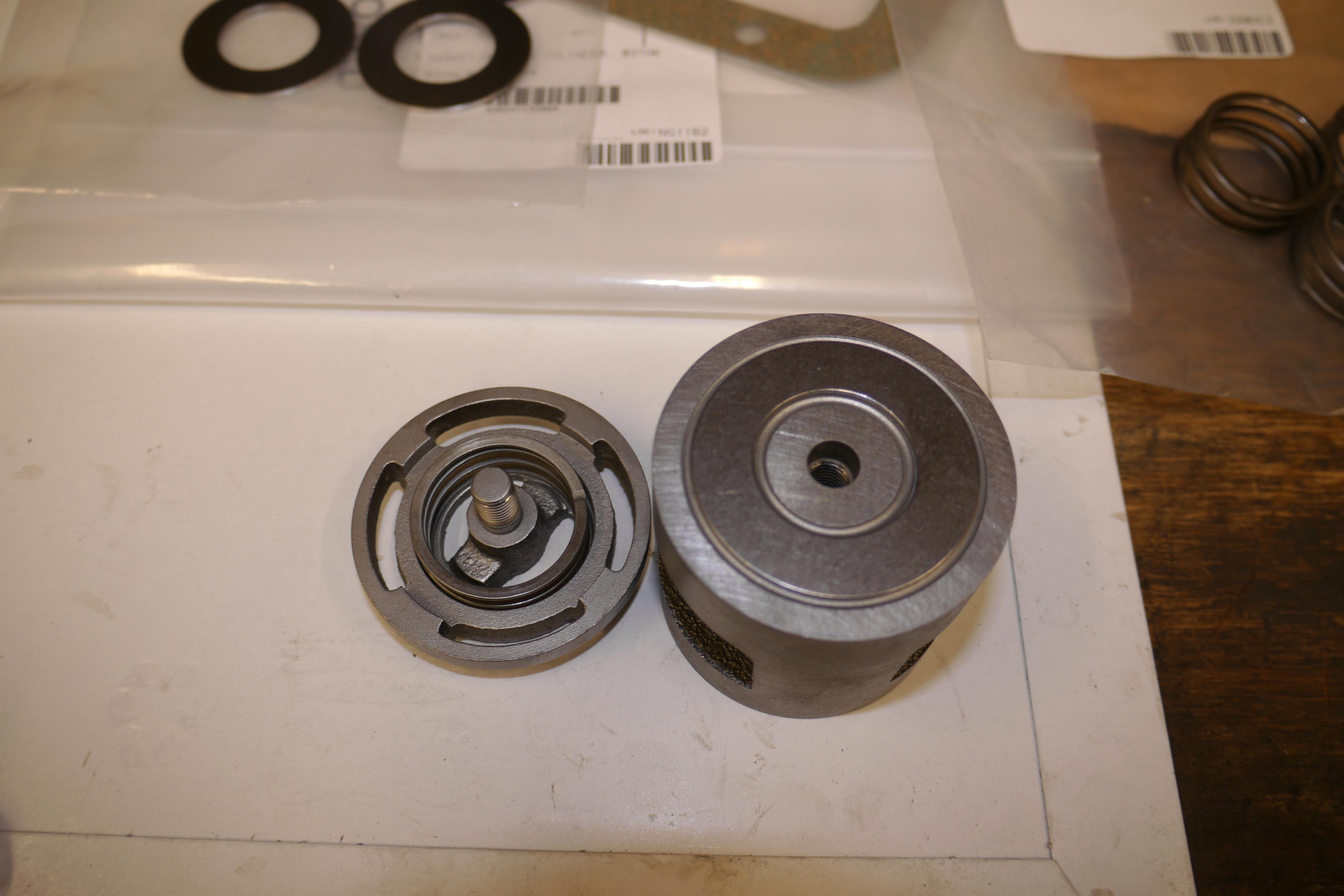
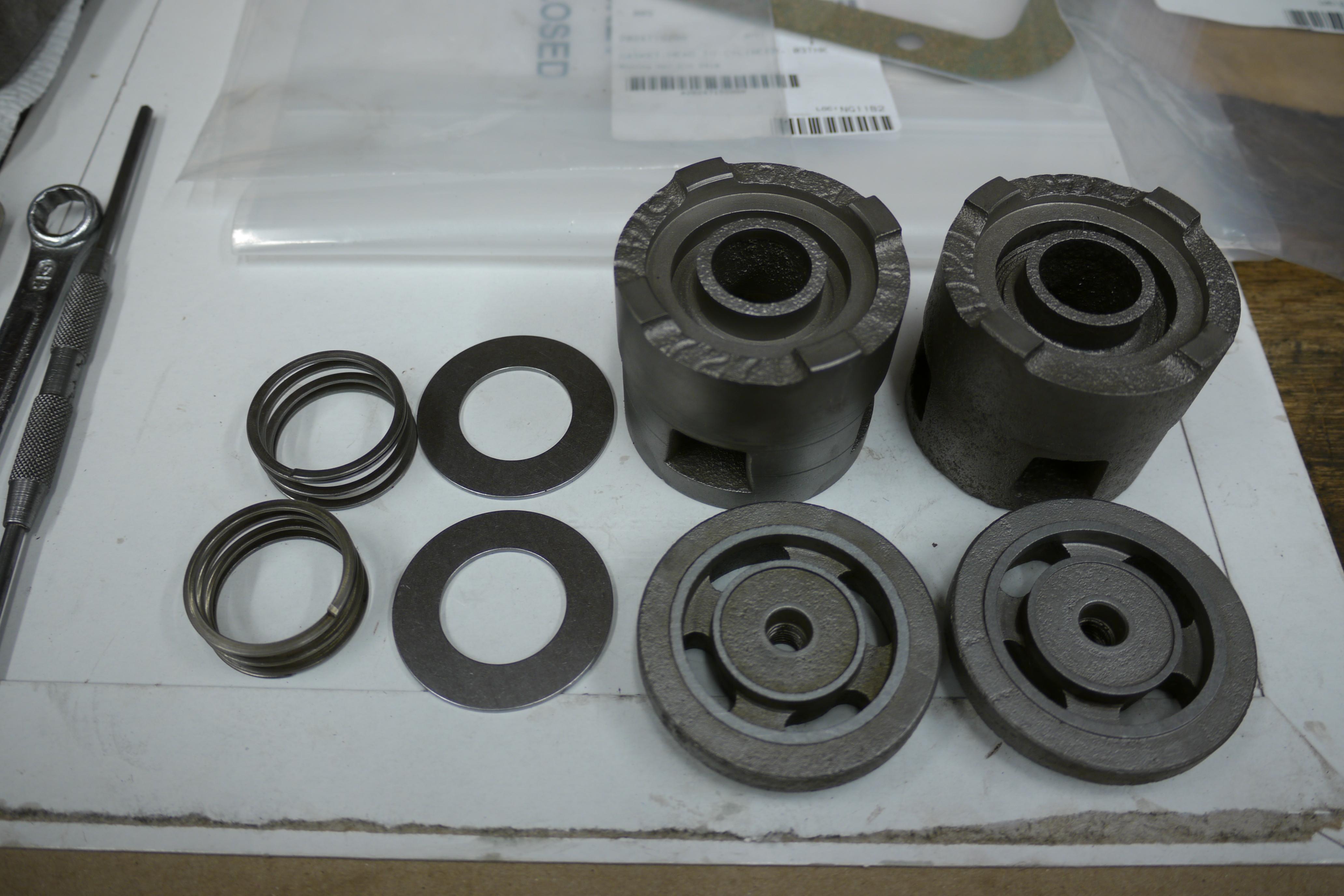
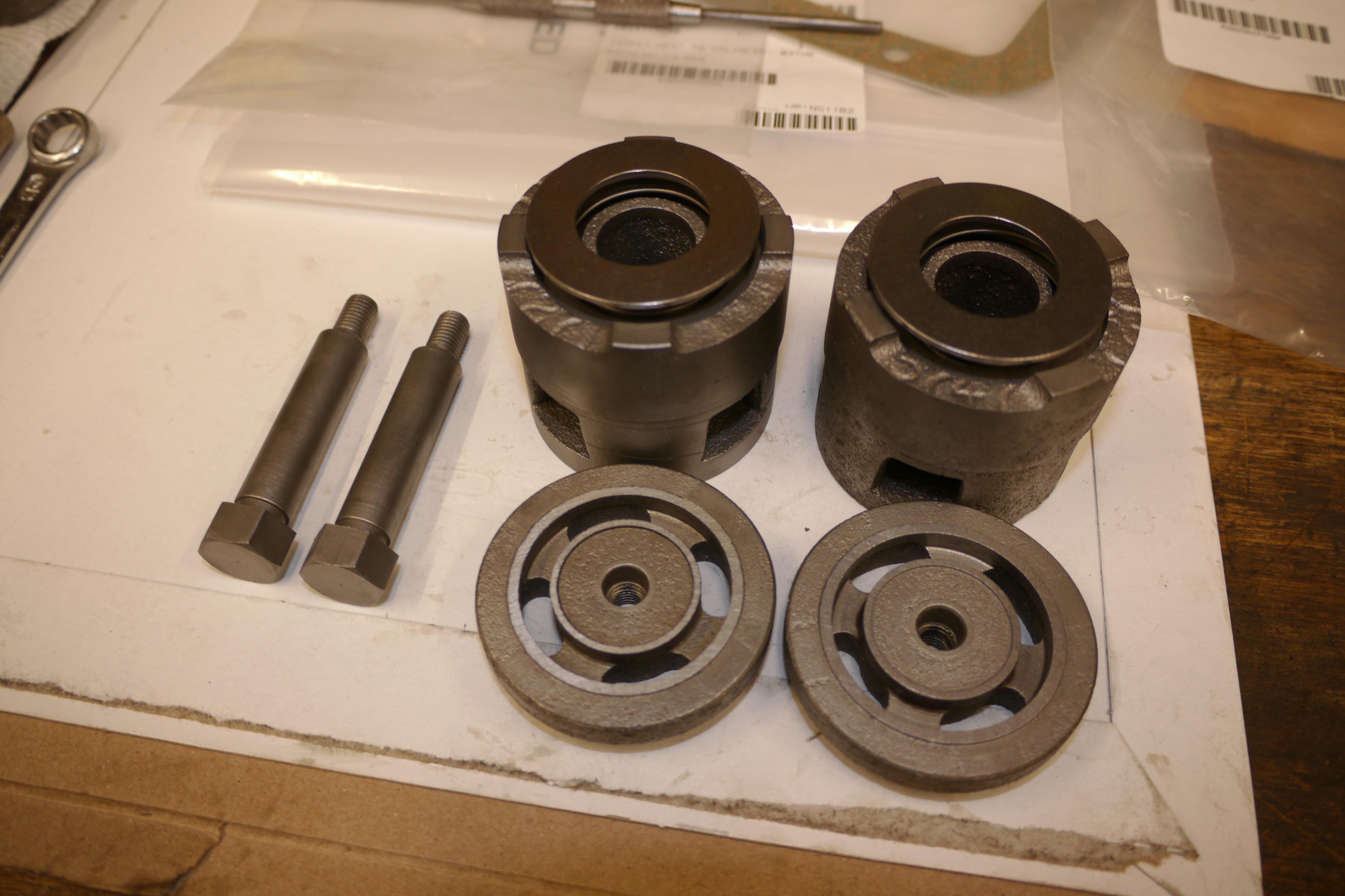
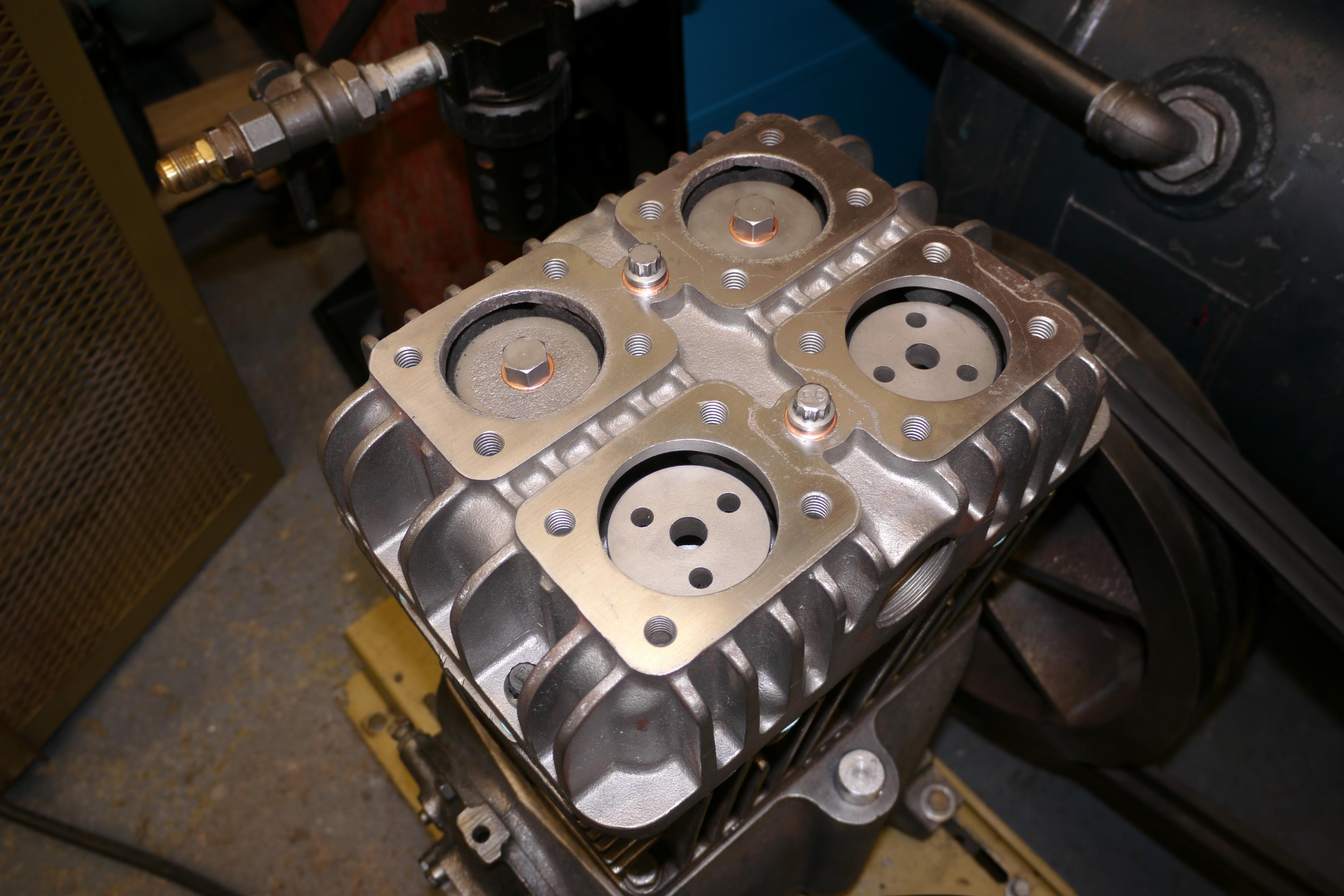
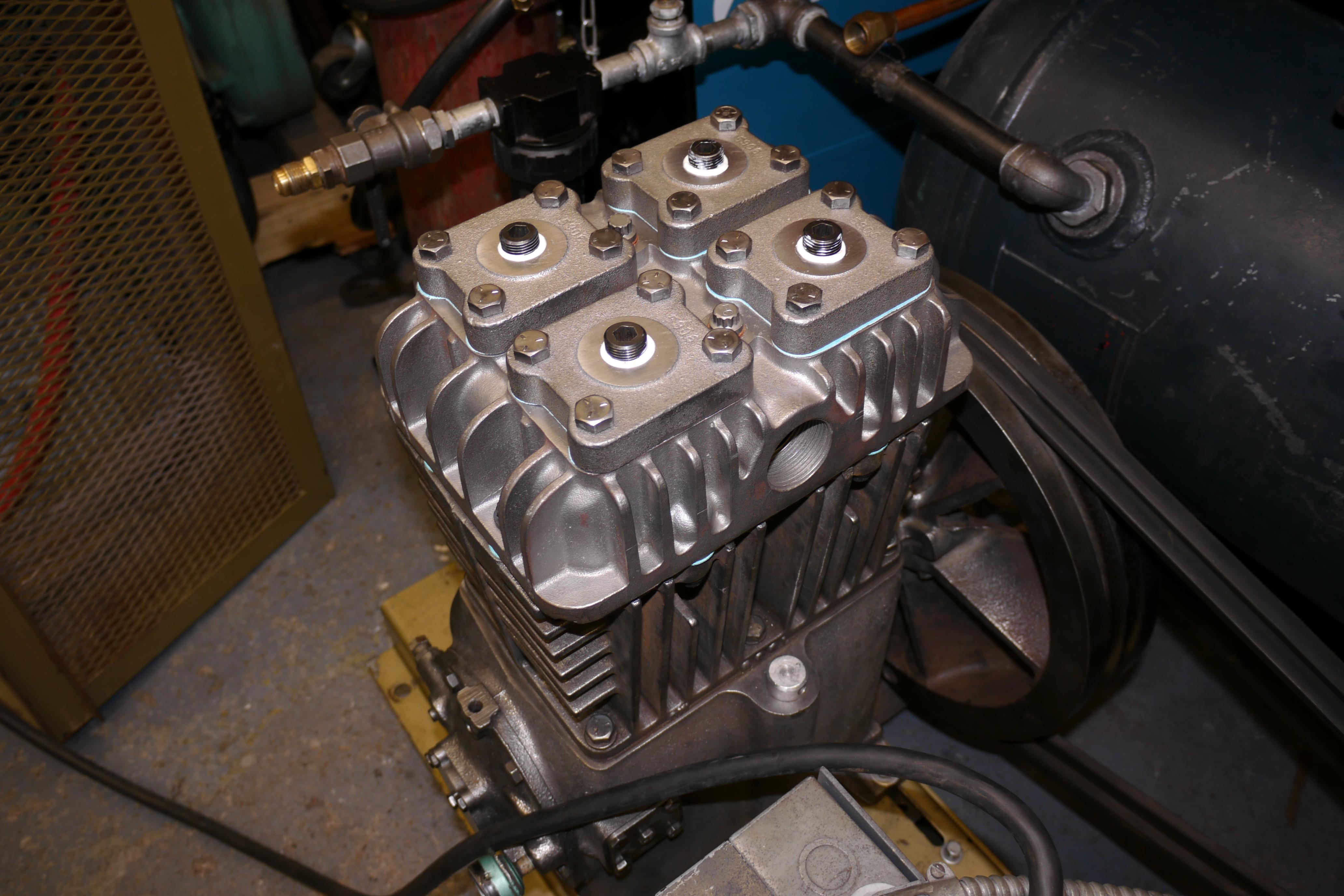
Now that the cylinder head has been installed, all that remains is the assembly of the intake and discharge valves. When I was at Scales Compressor, Mike Engesser informed me that the valv esprings used in my Quincy 230 compressor have been supersceded three times since my compressor was built, and handed me a set of current valve springs. These valve springs provide much more support to the valve disc. Cesar informed me what parts of the valve bodies to clean up and flatten, paying close attention to the cast ribs in the valve bumpers to be sure that the valve cannot hangup. These pictures show the rebuild of a Quincy 230 intake valve.


The discharge valves are setup a little different than the intake valves. The valve bumper is threaded onto the valve body, rather than being a part of the valve body itself. The assembly is for the most part just backwards. The only real difference in assembly is that the screw post runs through the valve body and threads into the valve bumper. A copper washer is used on the top of the post, and anti-seize on the threaded end to ease removal in the future.

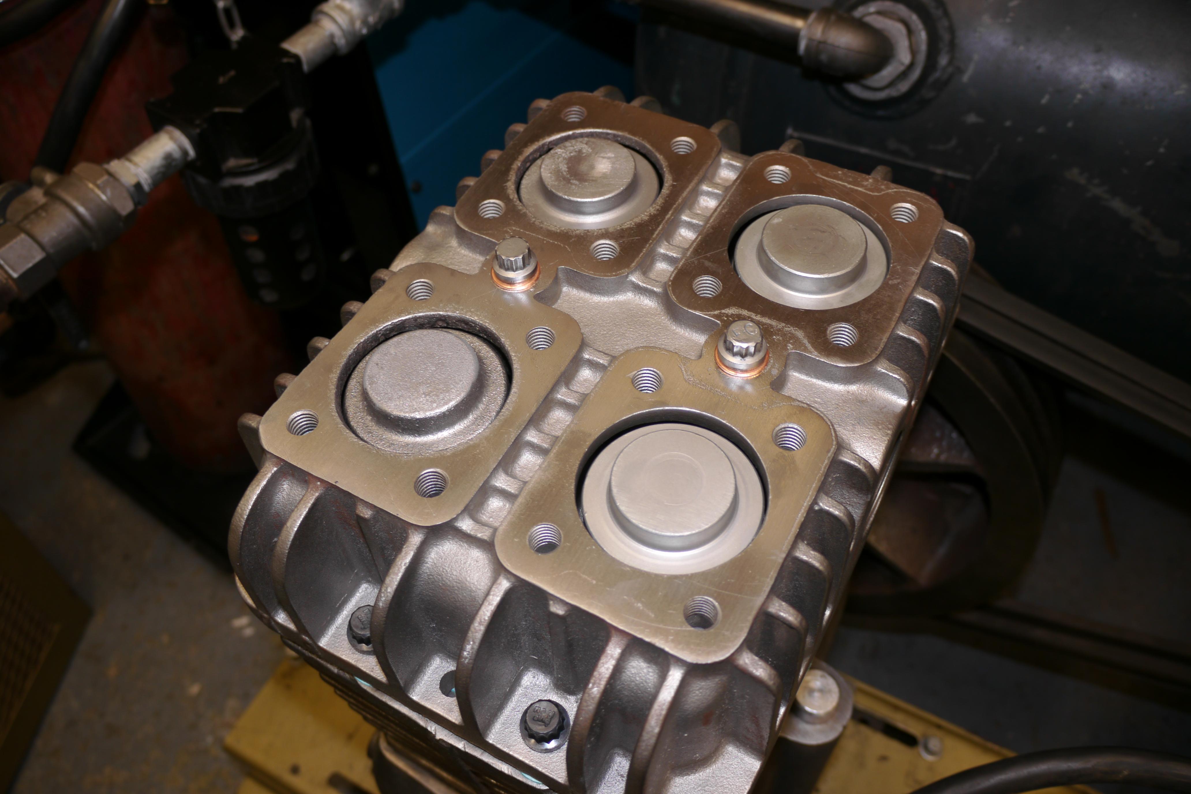
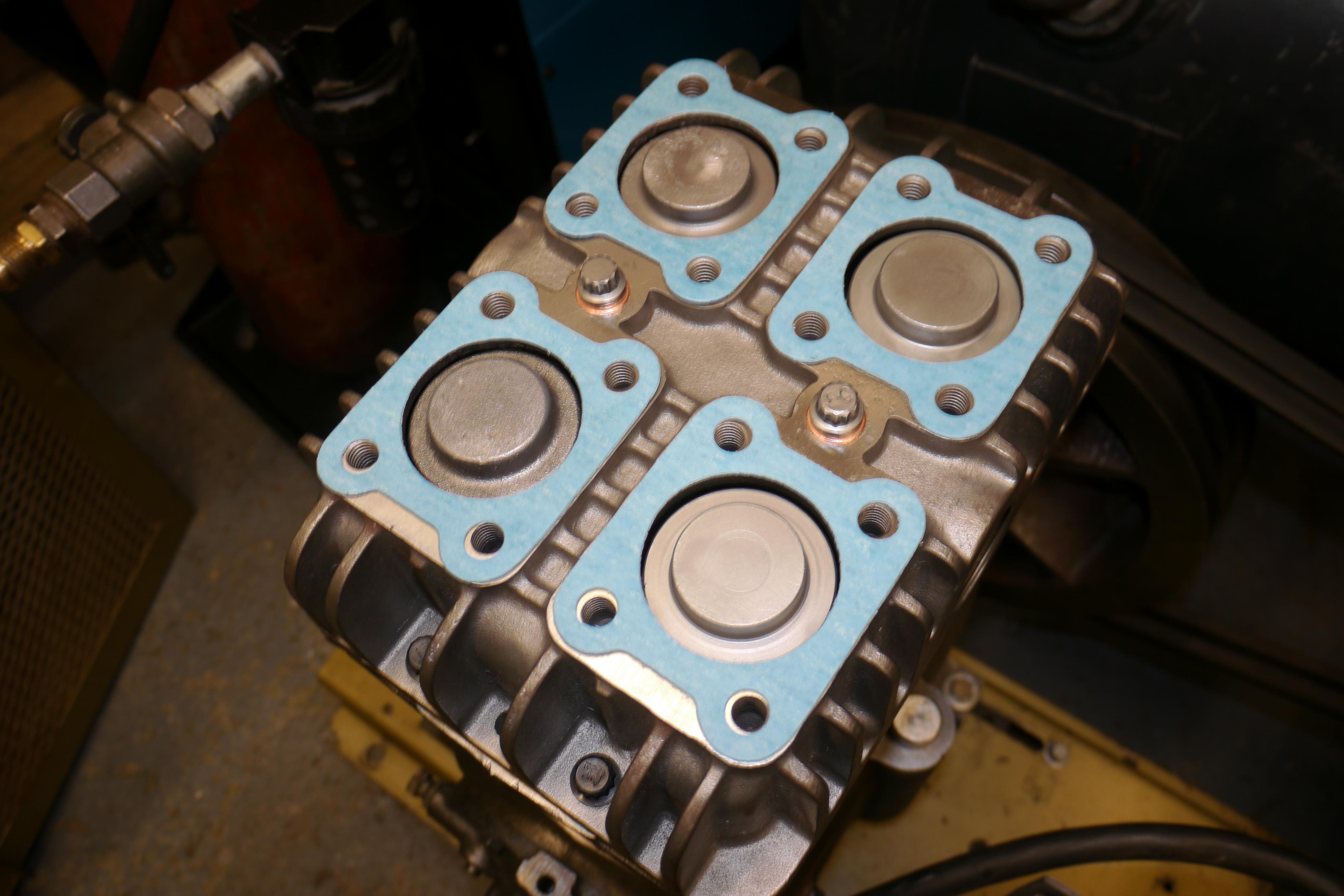
The intake and discharge valves are now installed and topped with the valve hold downs. Due to the condition of these valve hold downs, most of them were replaced. Genuine Quincy valve cover gaskets were installed, and the valve covers were lightly sanded on the surface block to ensure a good seal. Cesar told me a trick about installing the valve covers; apply thread sealant to the lower threads, and then anti-seize on the upper threads. When installed the sealant will prevent air leaks, and the anti-seize will prevent the bolts from rusting in place. The opposite is used on the actual valve hold down screws. Anti-seize on the bottom threads, and thread sealant on the upper threads.
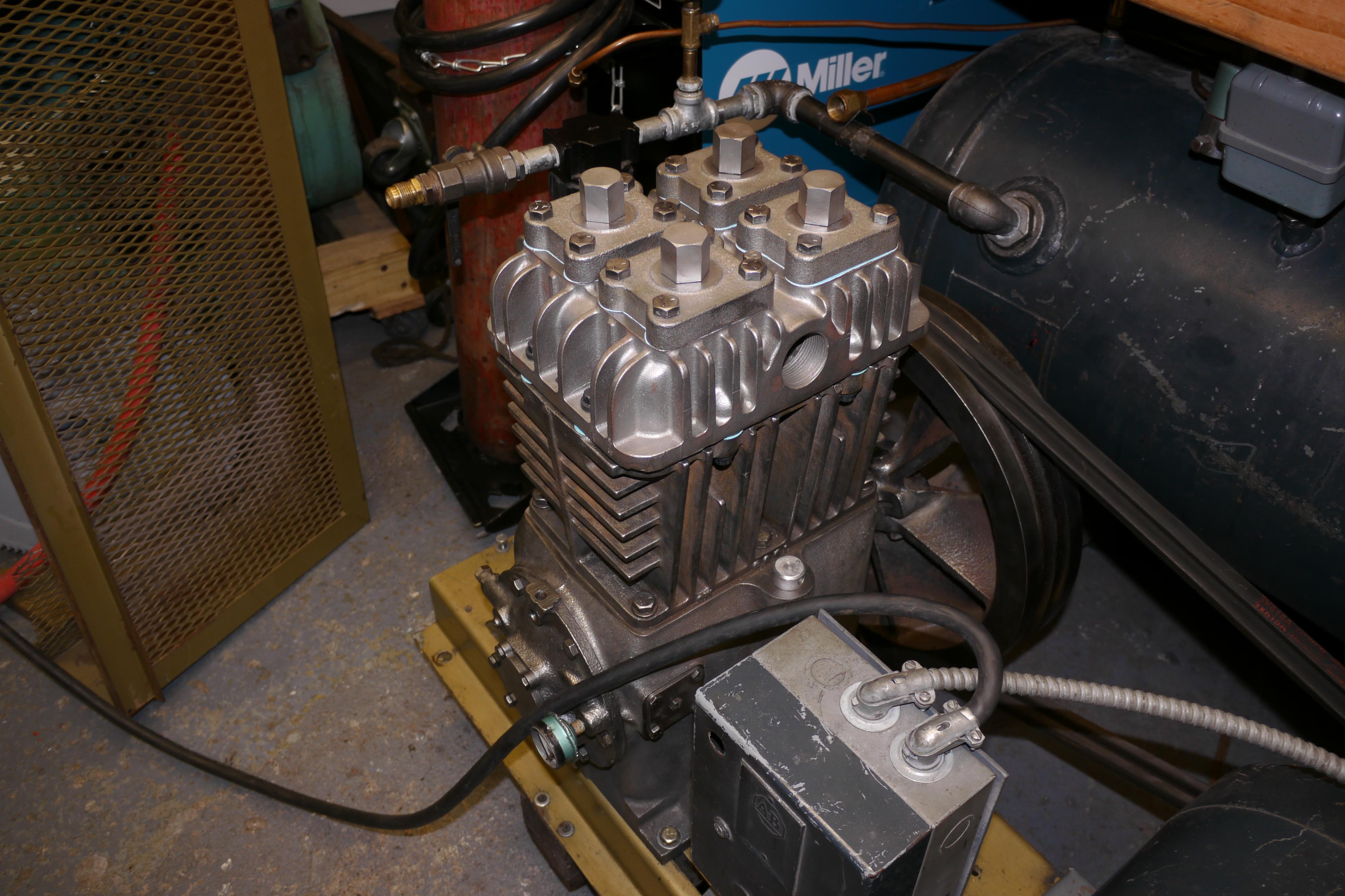
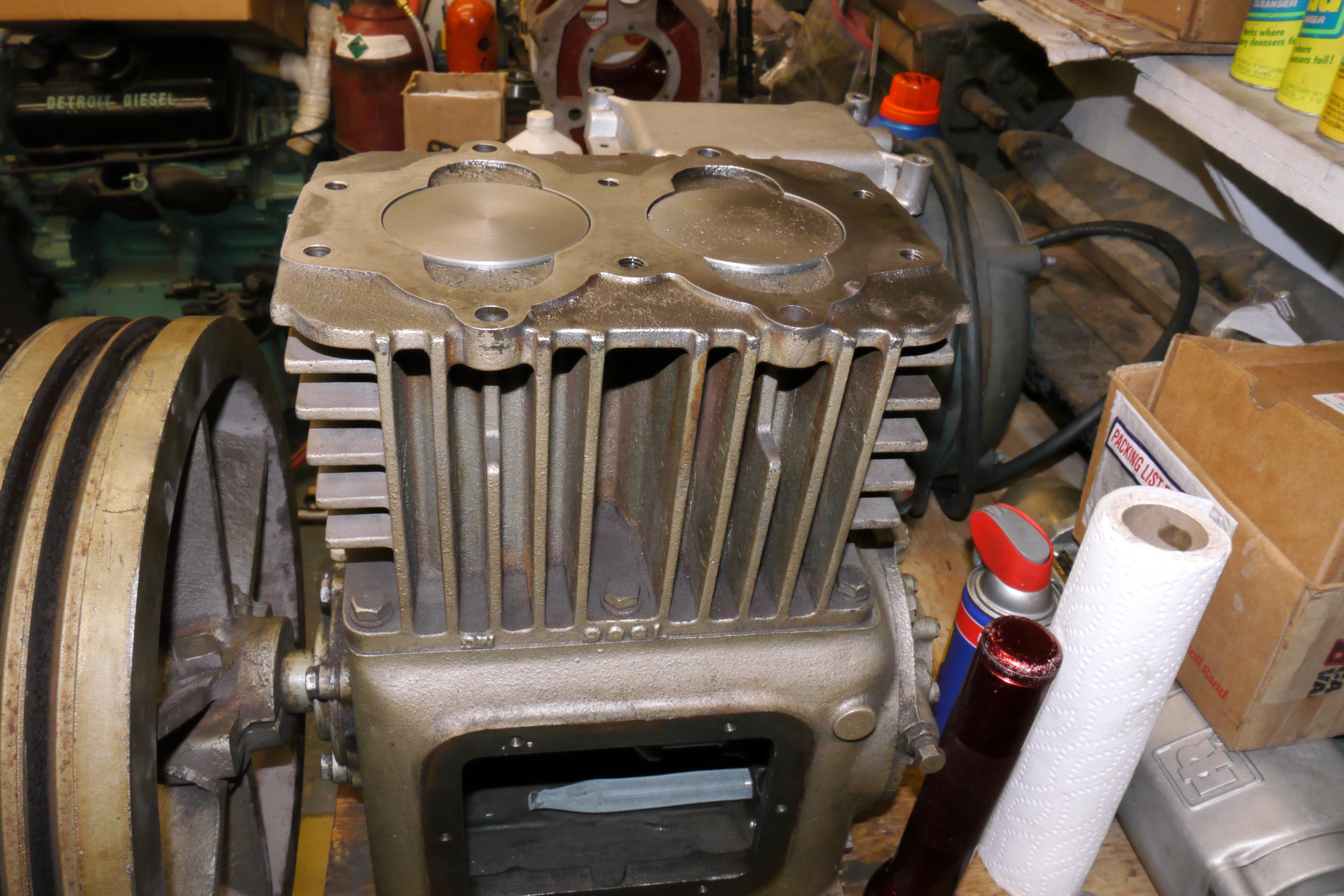
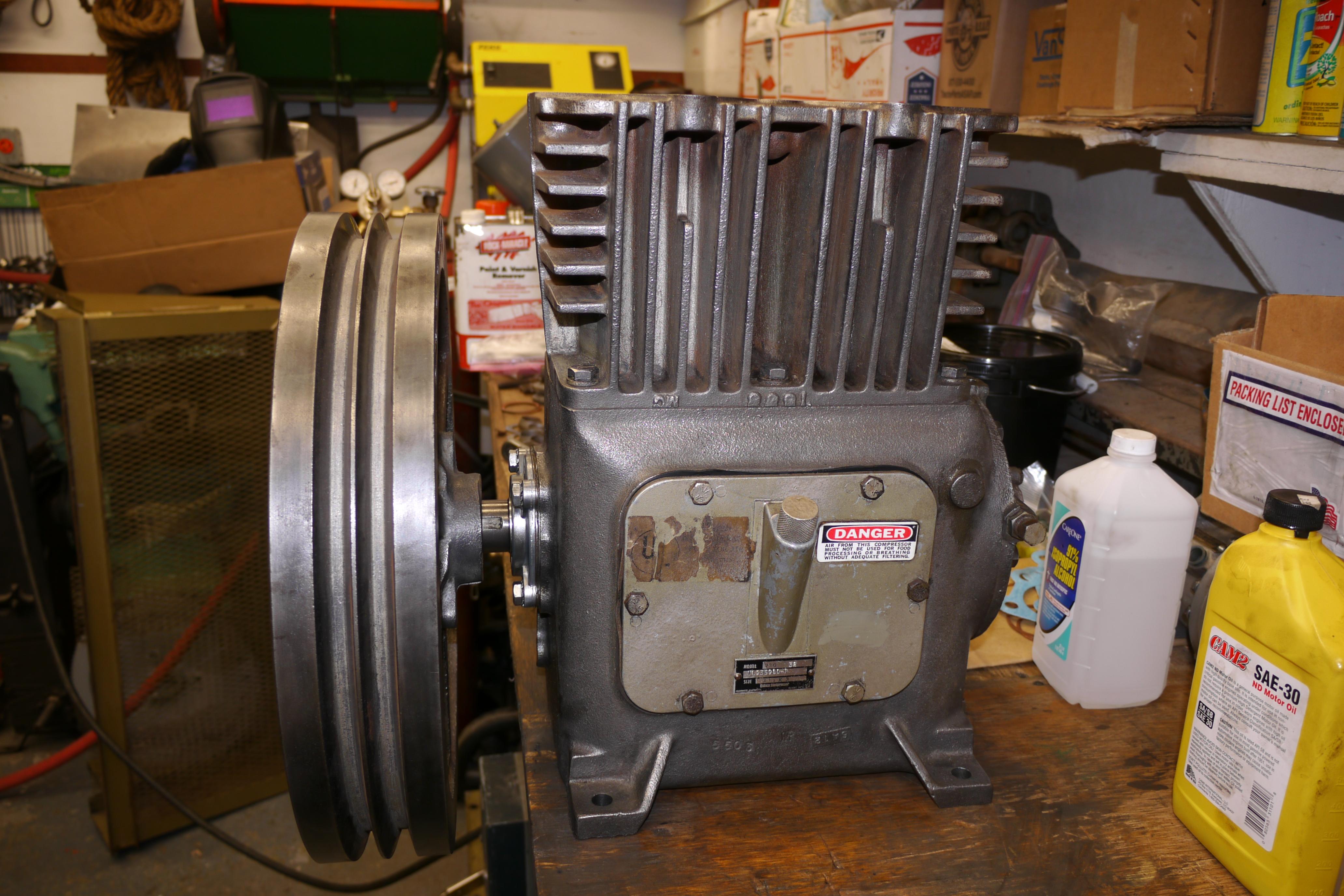
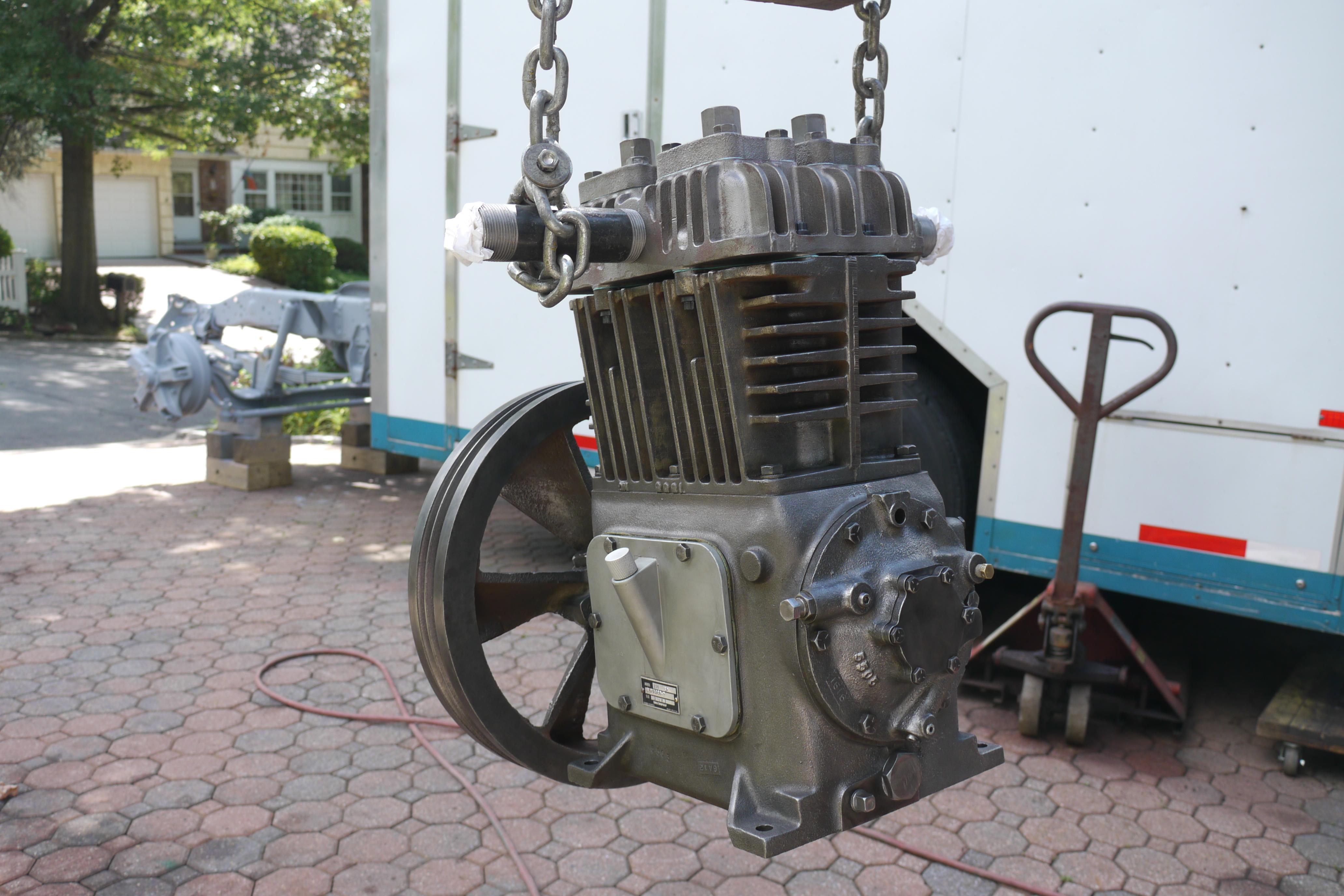
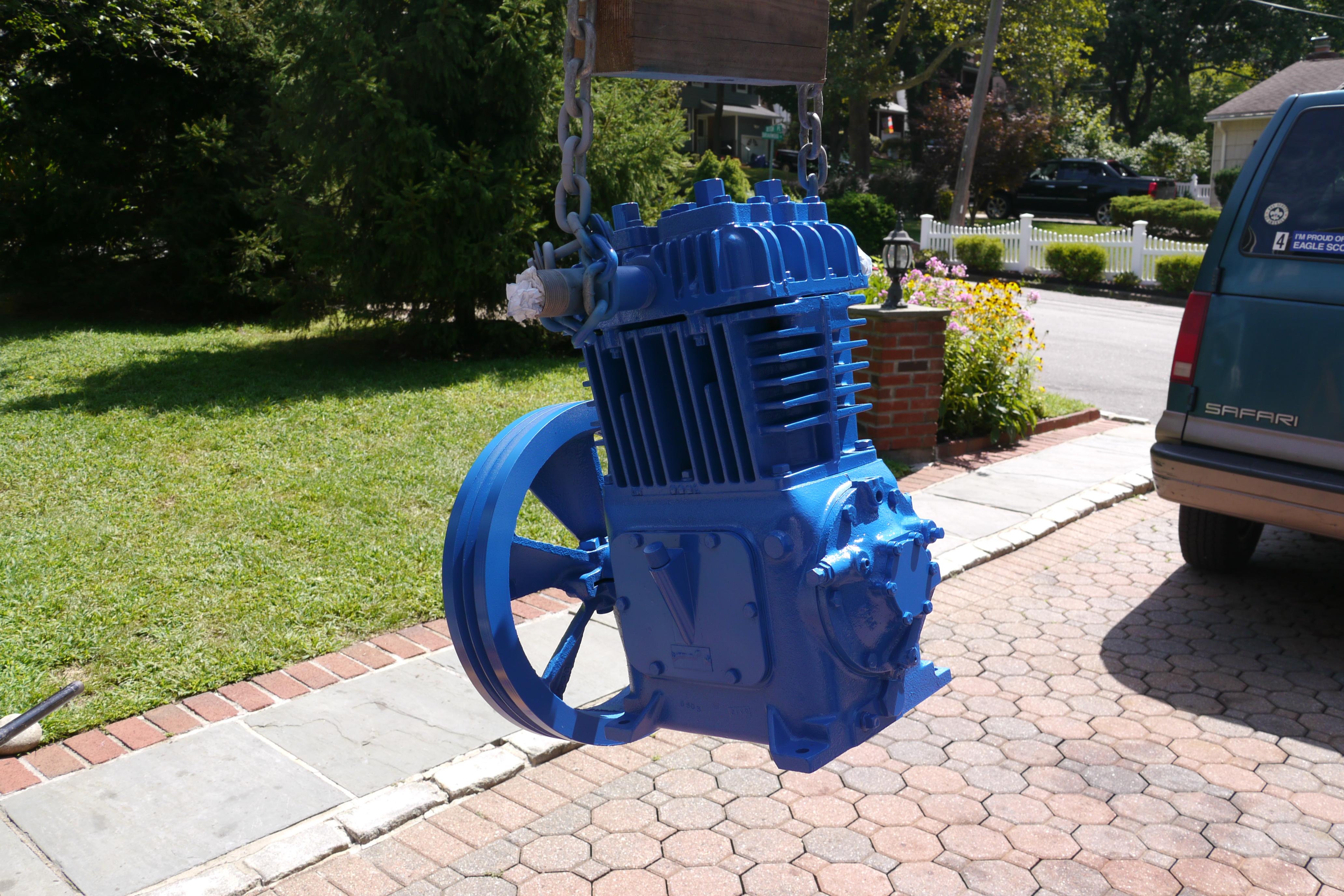
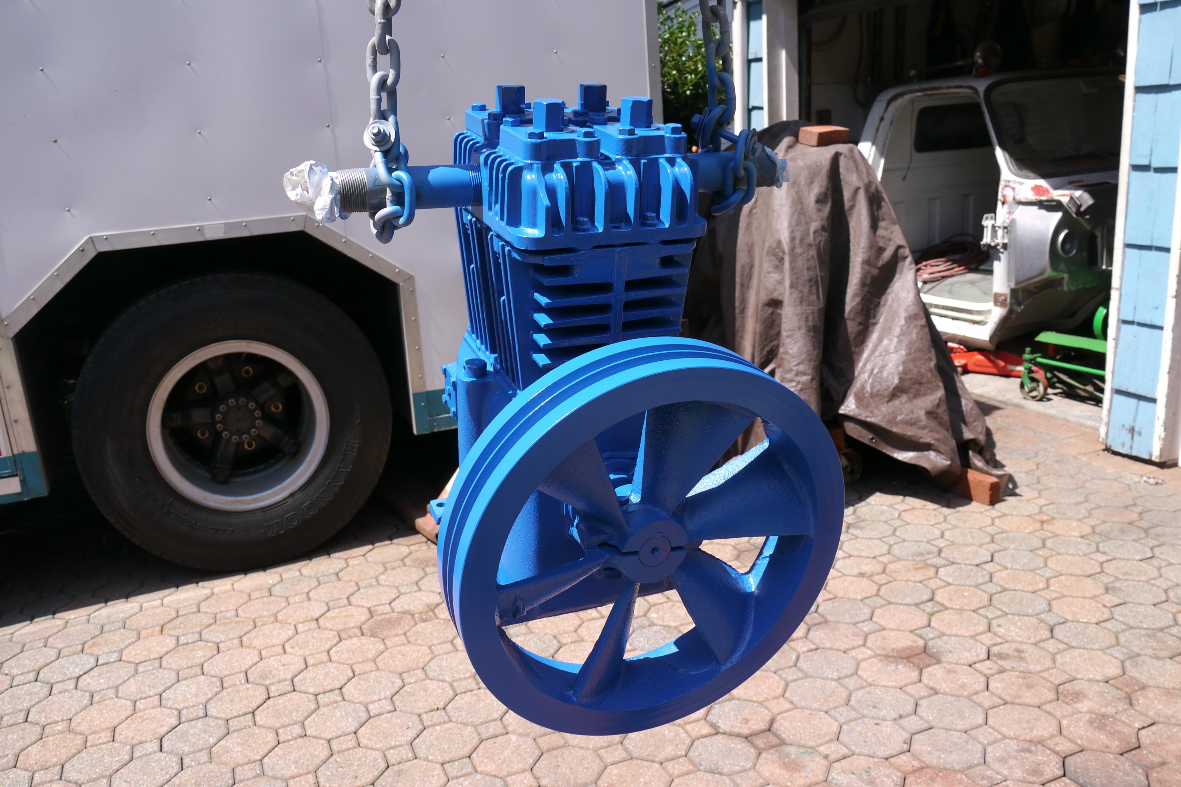
The compressor is now complete. It just needs to be primed and painted. Due to the weight of this compressor, I threaded two 1-1/4" pipe nipples into the head so that I could suspend the compressor for a complete and thorough paint job. Before painting, I washed the compressor down with denatured rubbing alcohol and let it air dry in the sun. Once thoroughly clean, I sprayed the compressor with primer. The next day I laid down two coats of Quincy Blue II, the current color of Quincy compressors. Sadly Scales Compressor did not have an original paint code for the original Quincy "Green Gold" color my compressor was. It looks good in blue.

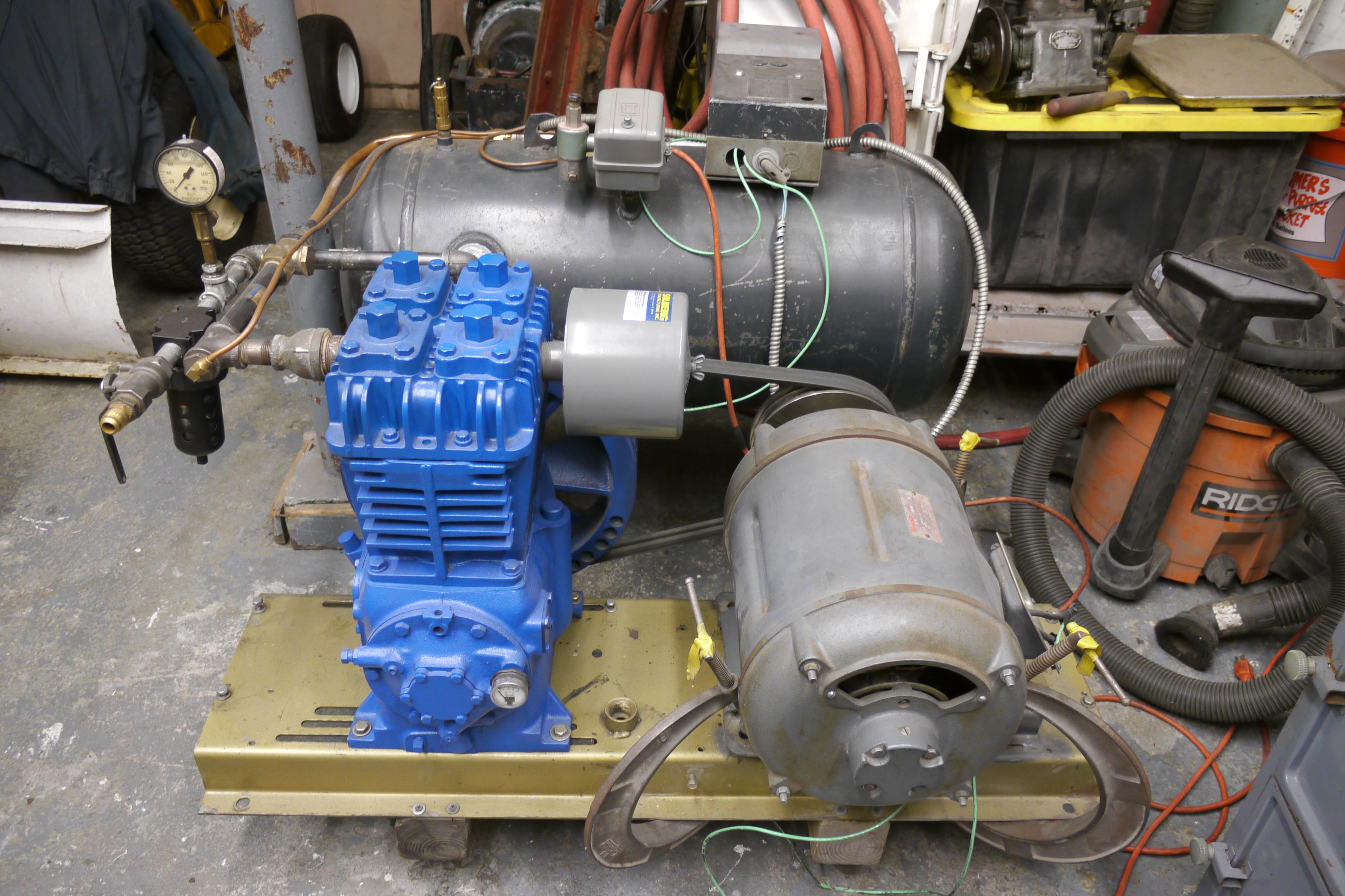
Once the paint dried, I mounted my newly rebuilt 1968 Quincy 230-32 compressor back onto the compressor plate that came with the compressor I bought. I aligned & tensioned the drive belts and powered it up for the first time. I watched the compressor slowly build air pressure up to 100psi and shut off, listening for any unusual noises. For several weeks I kept an eye on the running temperature of the compressor, the oil pressure, and any unusual noises it made. The compressor ran like a swiss watch and did not miss a beat. After approximately twenty hours of runtime at 550rpm, I swapped the 3 horsepower motor out for a 7.5 horsepower motor which was capable of driving the compressor at full speed, 885rpm. With this motor, cfm output of the compressor increased from 14.3 to 22.5cfm. Media blasting was finally enjoyable. The compressor matched the blasting nozzle just perfectly.
Thanks for Reading!
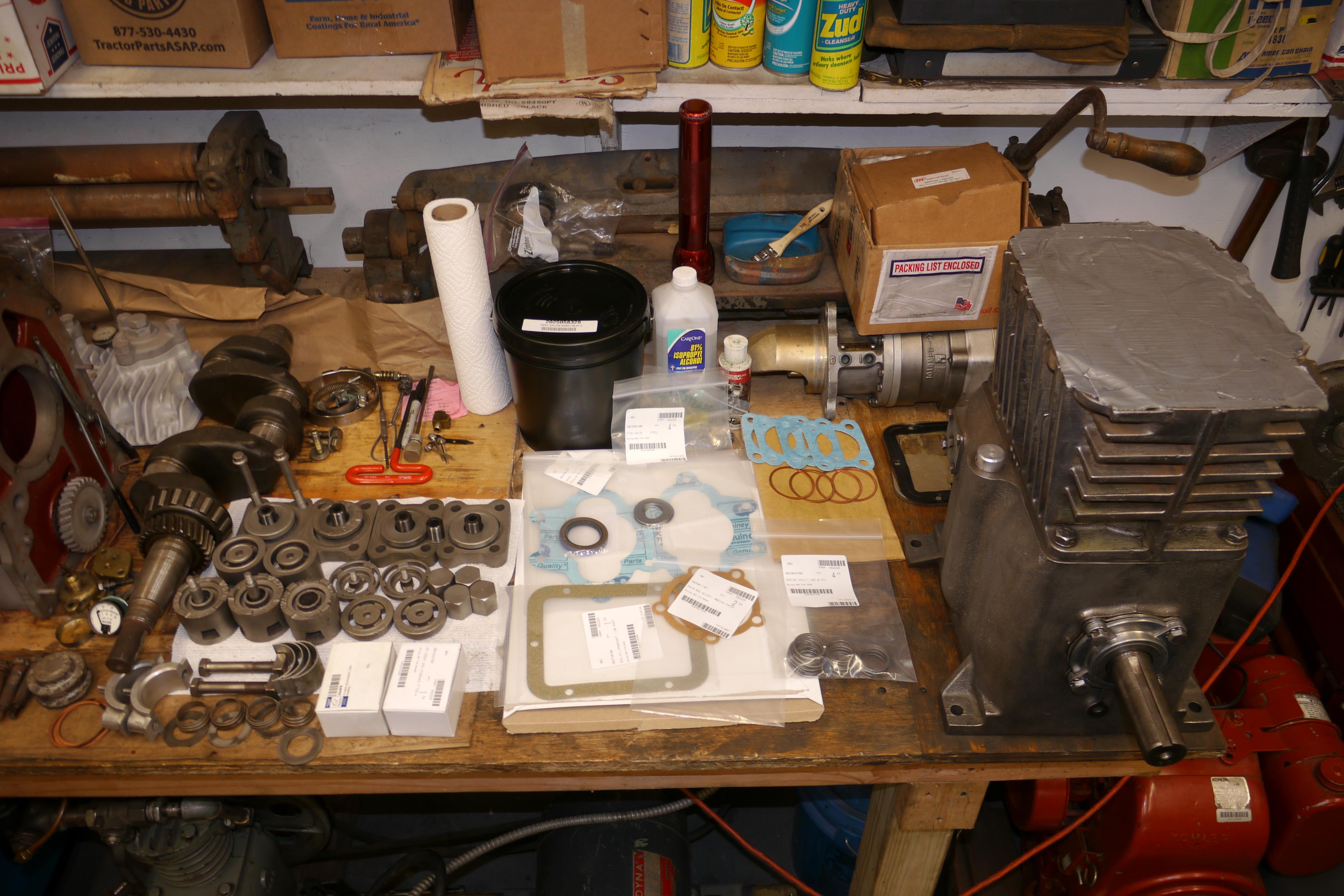
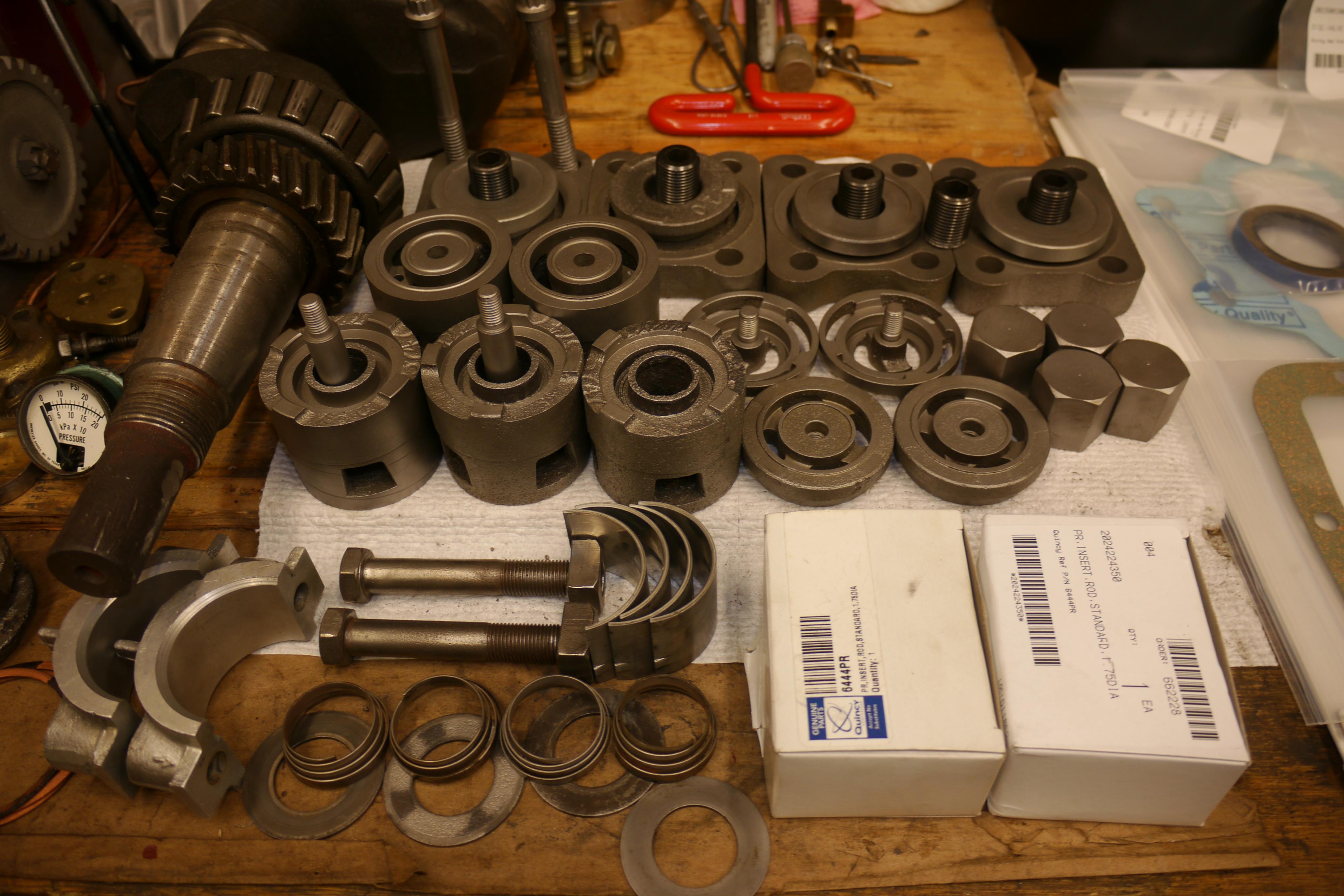
Want more? Here's a behind the scenes look at my workspace and some of the images that did not make the cut to be included in the write-up: