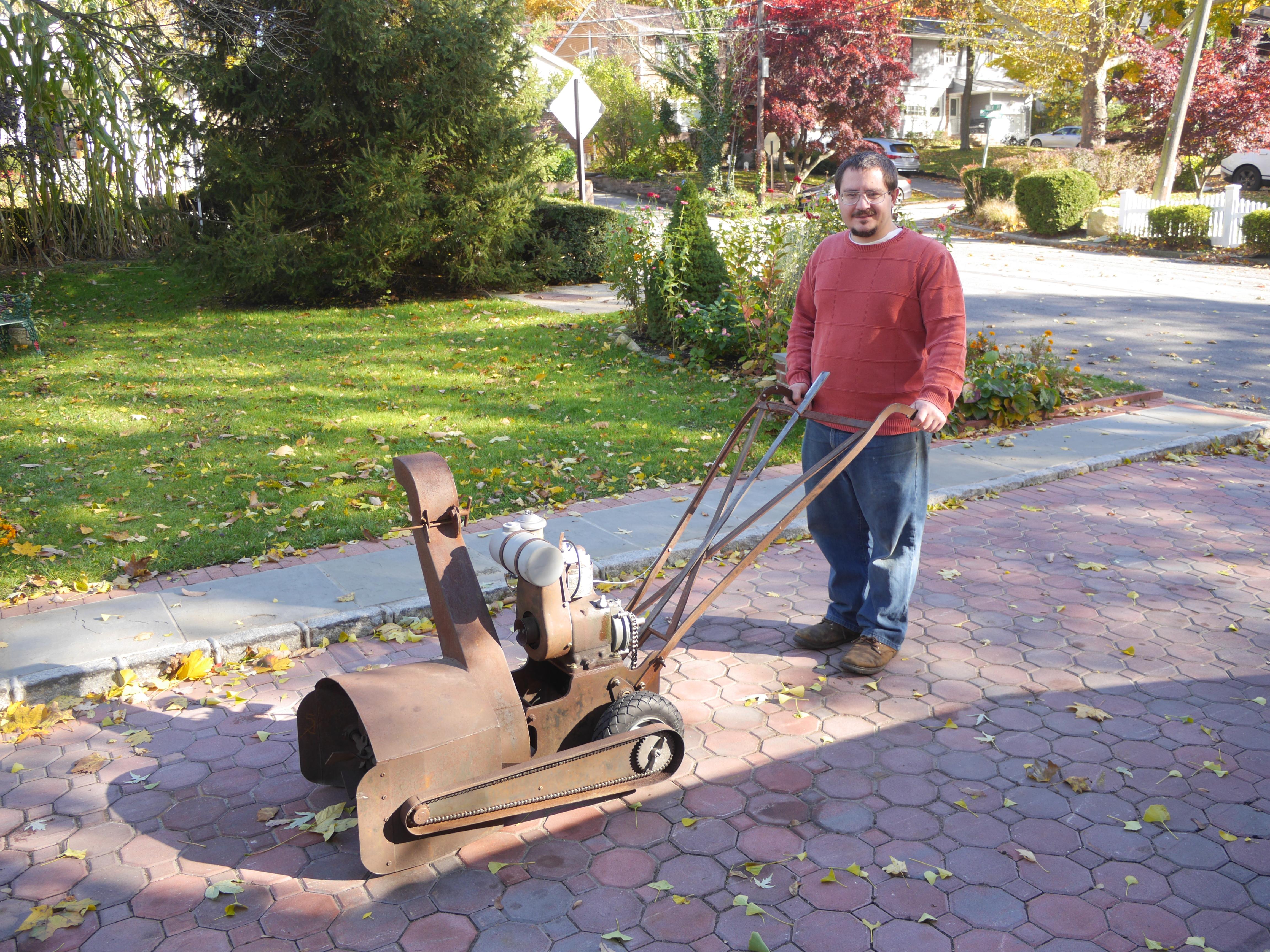
1949 Maxim Silencer 2-19 Snow Thrower

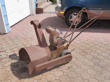
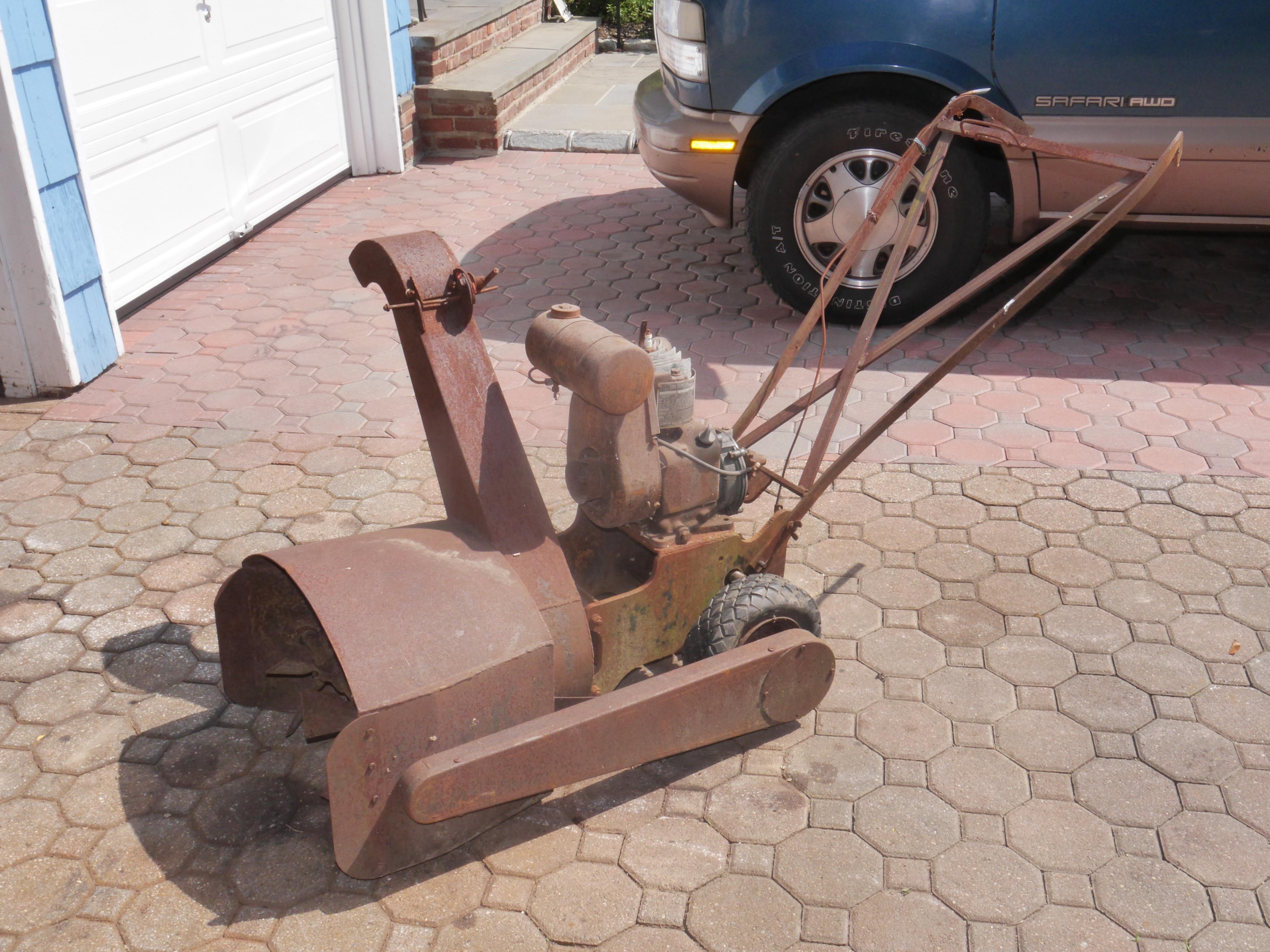
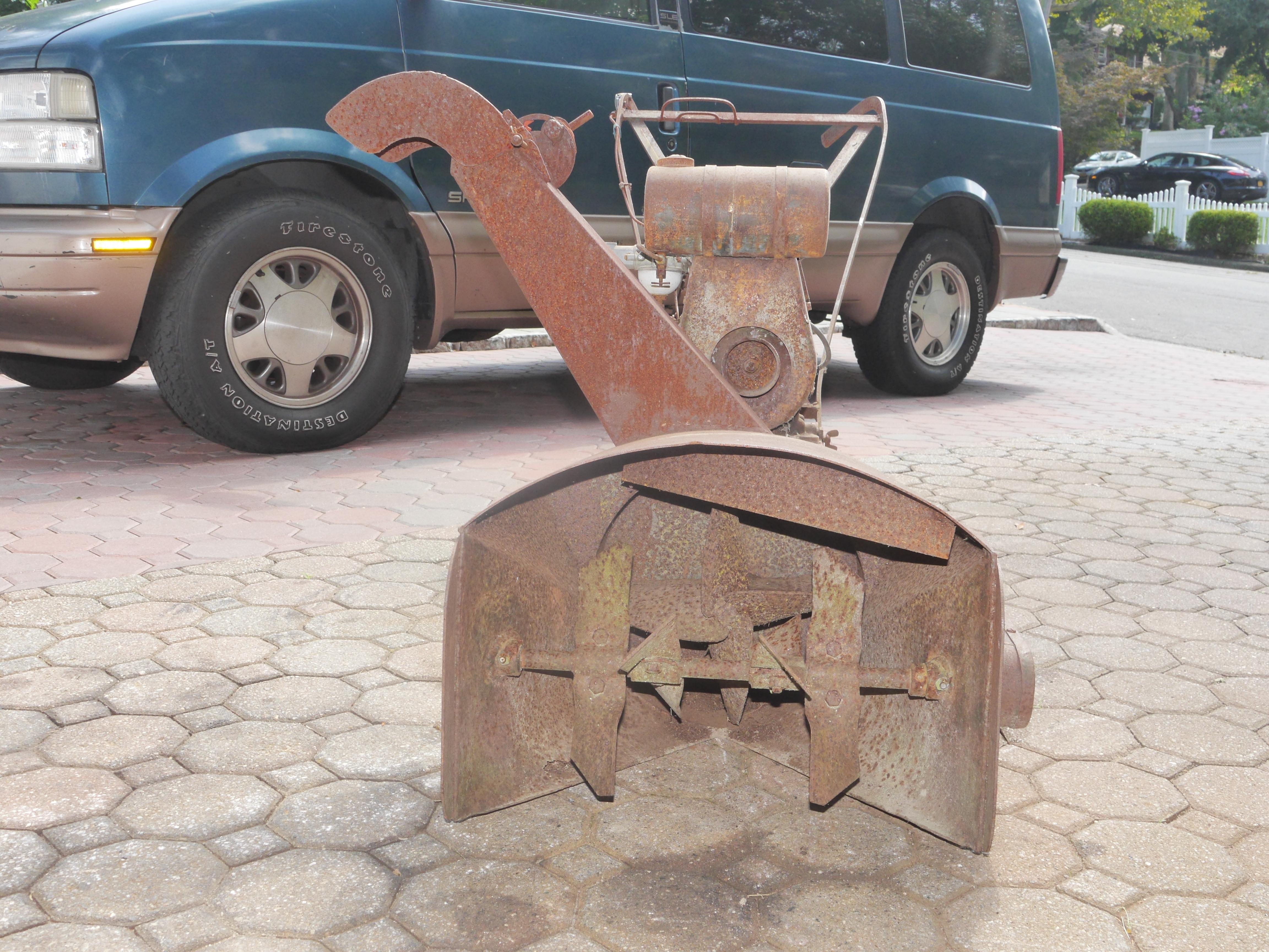
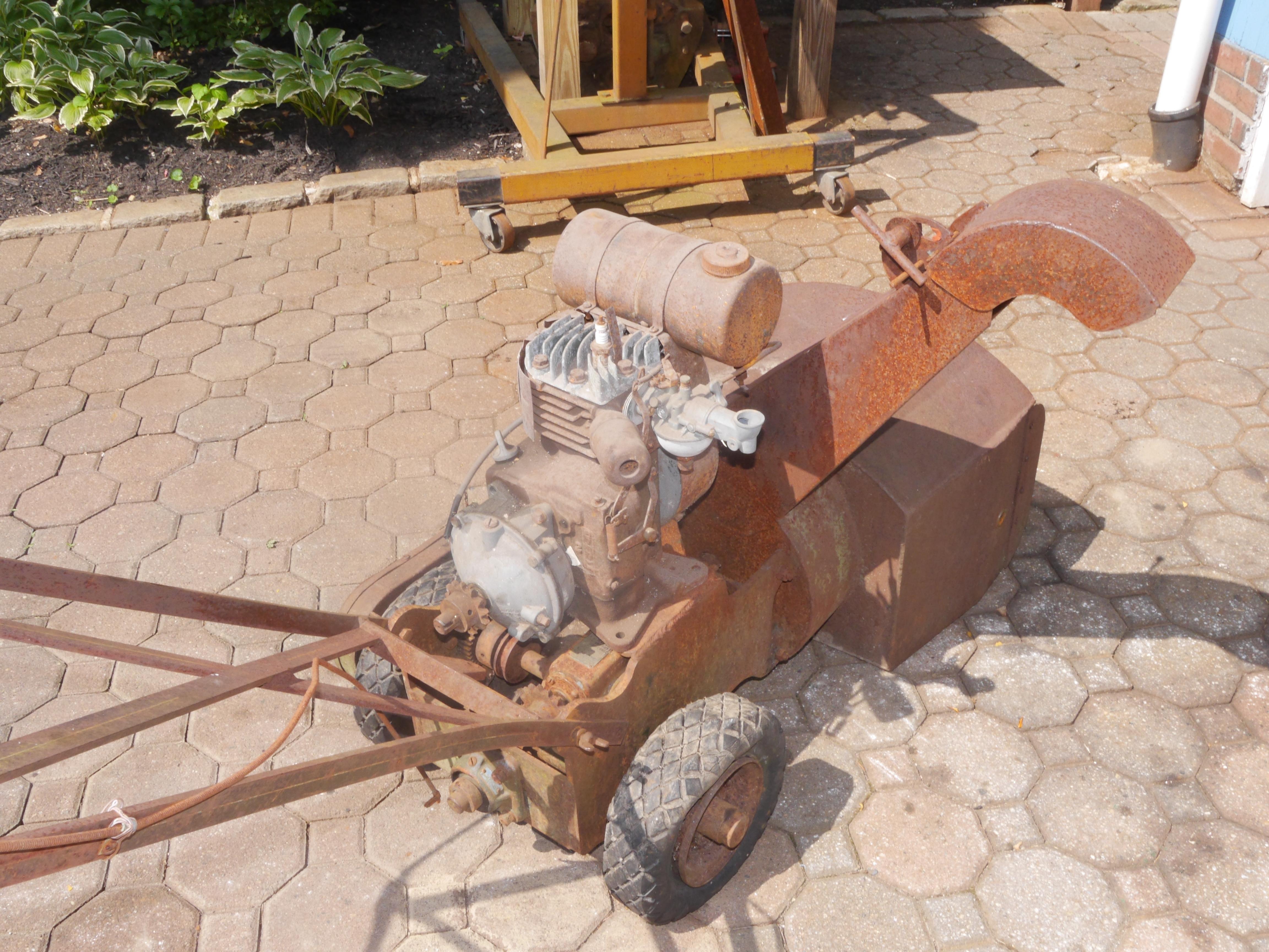
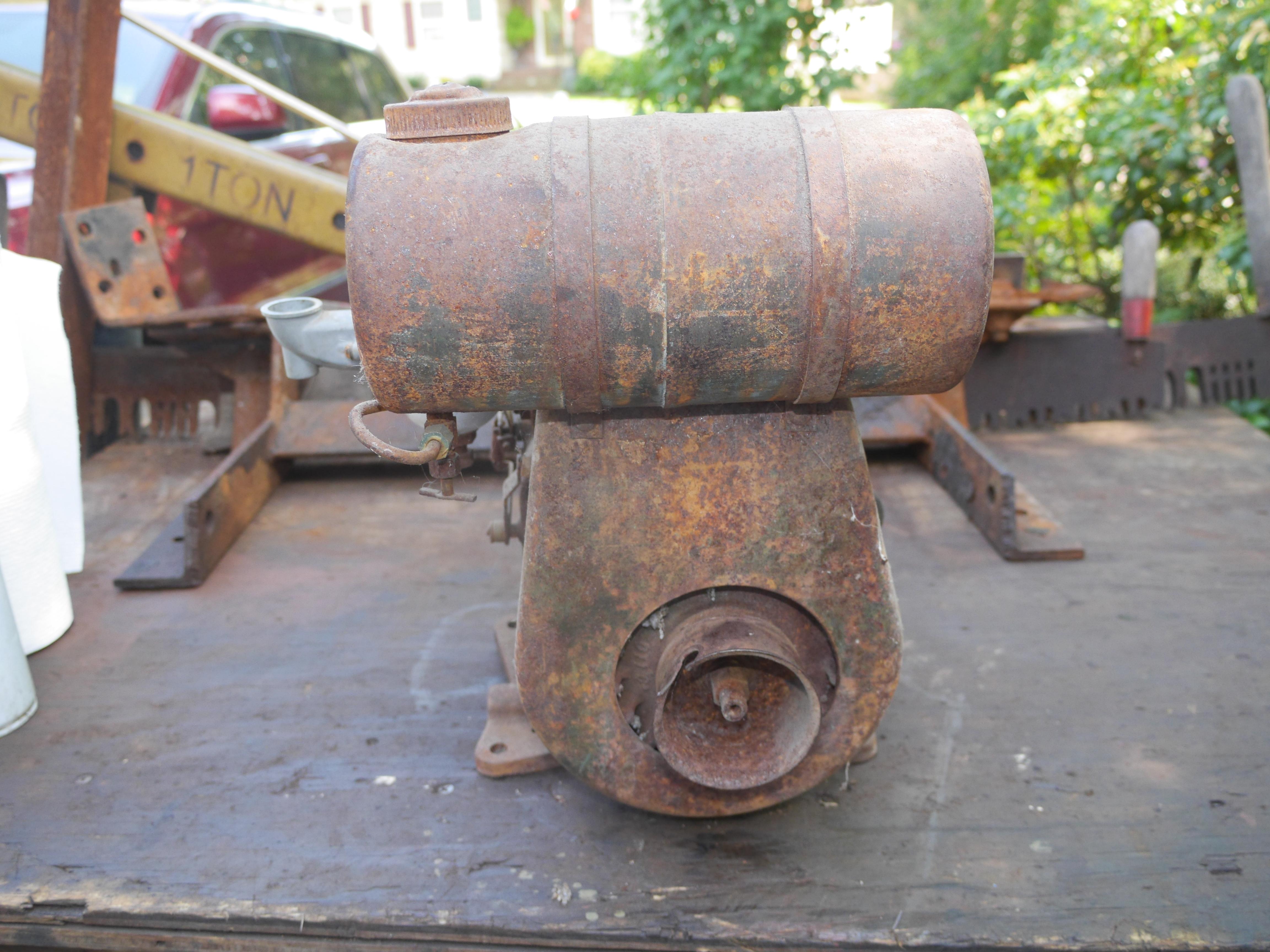
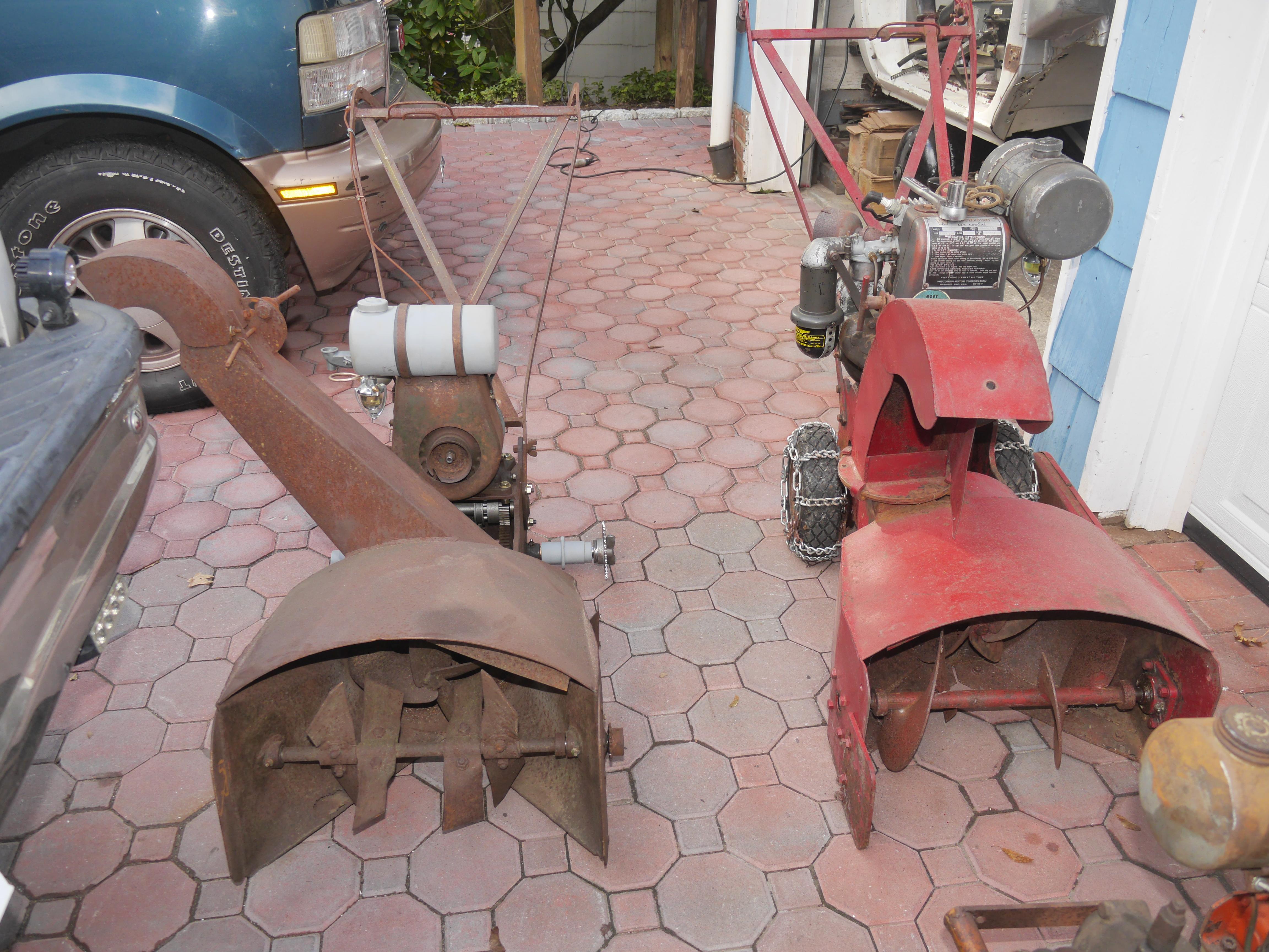
In December of 2017 I discovered a very rare and unsual Maxim Silencer snow thrower that I had not seen before. This particular unit was smaller than any that I have seen and was furnished with a Clinton engine. It took several months to finally convince the previous owner that it would have a better life in my garage than outside in his yard, so in September of 2018 I was able to save this snow thrower from eternal damnation. Those of you with an eye for old iron will note that there is another Maxim snow thrower sitting in the yard next to the little machine I picked up. I purchased this snow thrower as well, and will be featured in another restoration thread. For now we will focus on the smaller Maxim snow thrower.
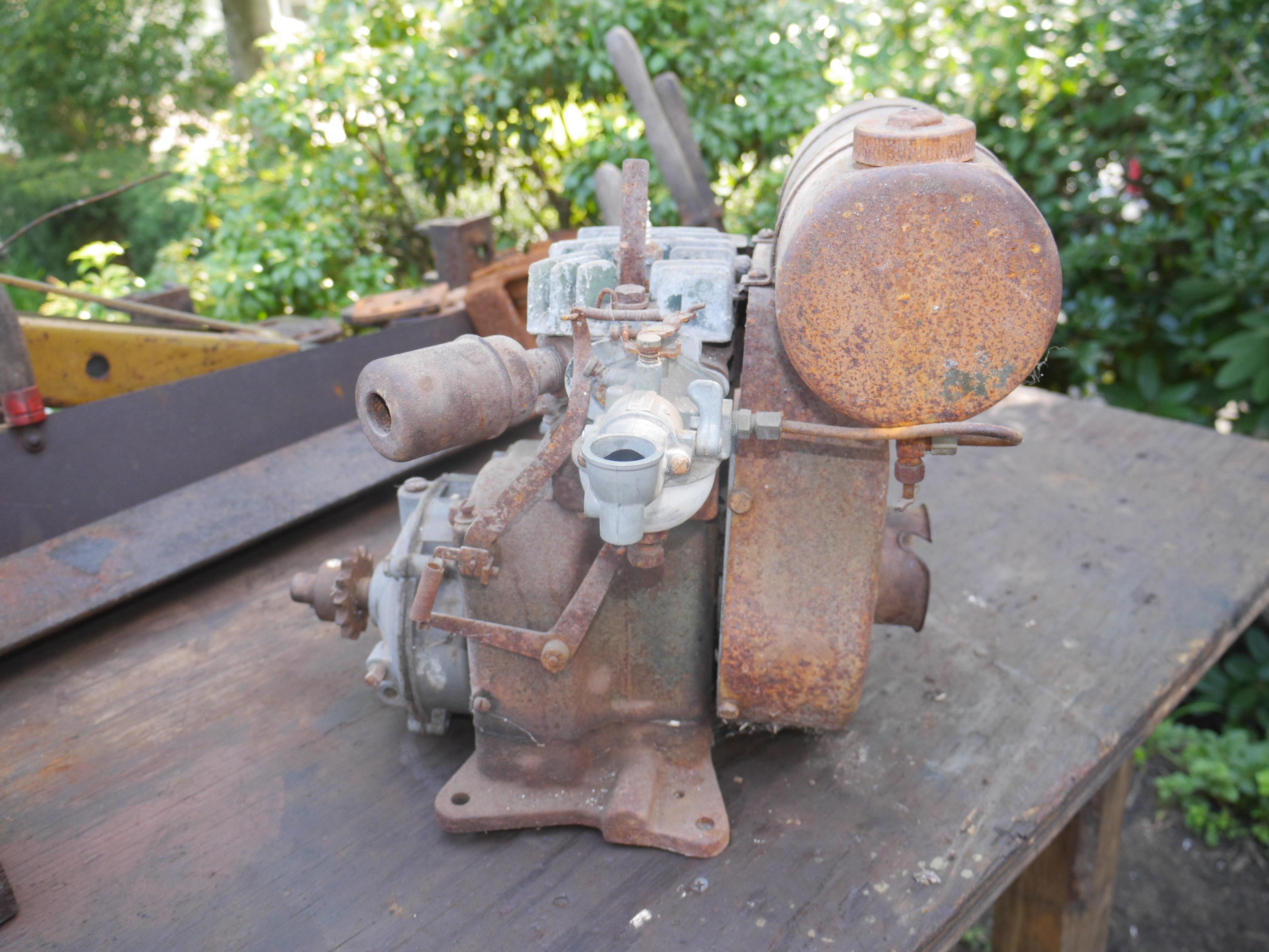
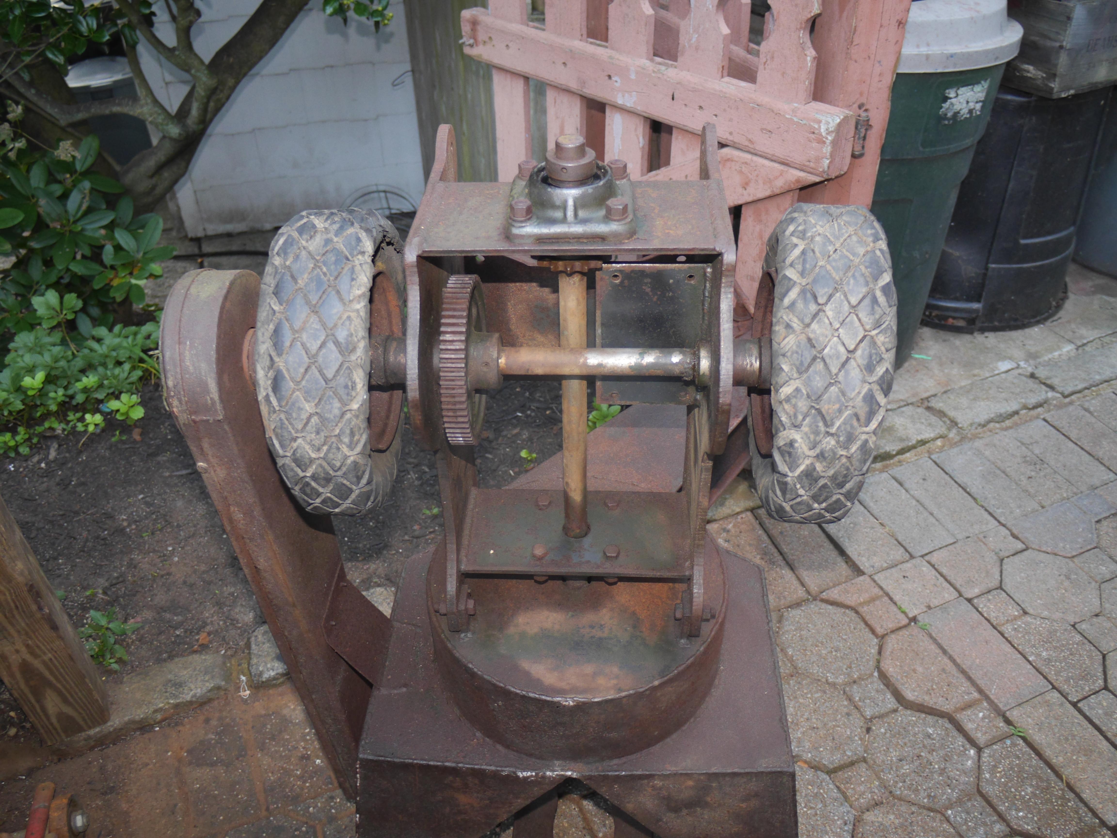
I normally do not buy equipment in such sad shape, but I have been collecting Maxim snow throwers for over five years now and have never seen one like it before. The engine was seized up, the transmission was apart in pieces for who knows how long, the clutch lever and linkages were missing, the axle was locked up, and it was evident that this machine has been sitting outside for the better part of its life. When I took these pictures, the machine was literally so far gone all of its detail was just rendered as a single blotch of rust.
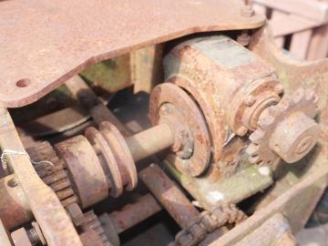
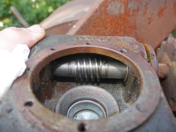
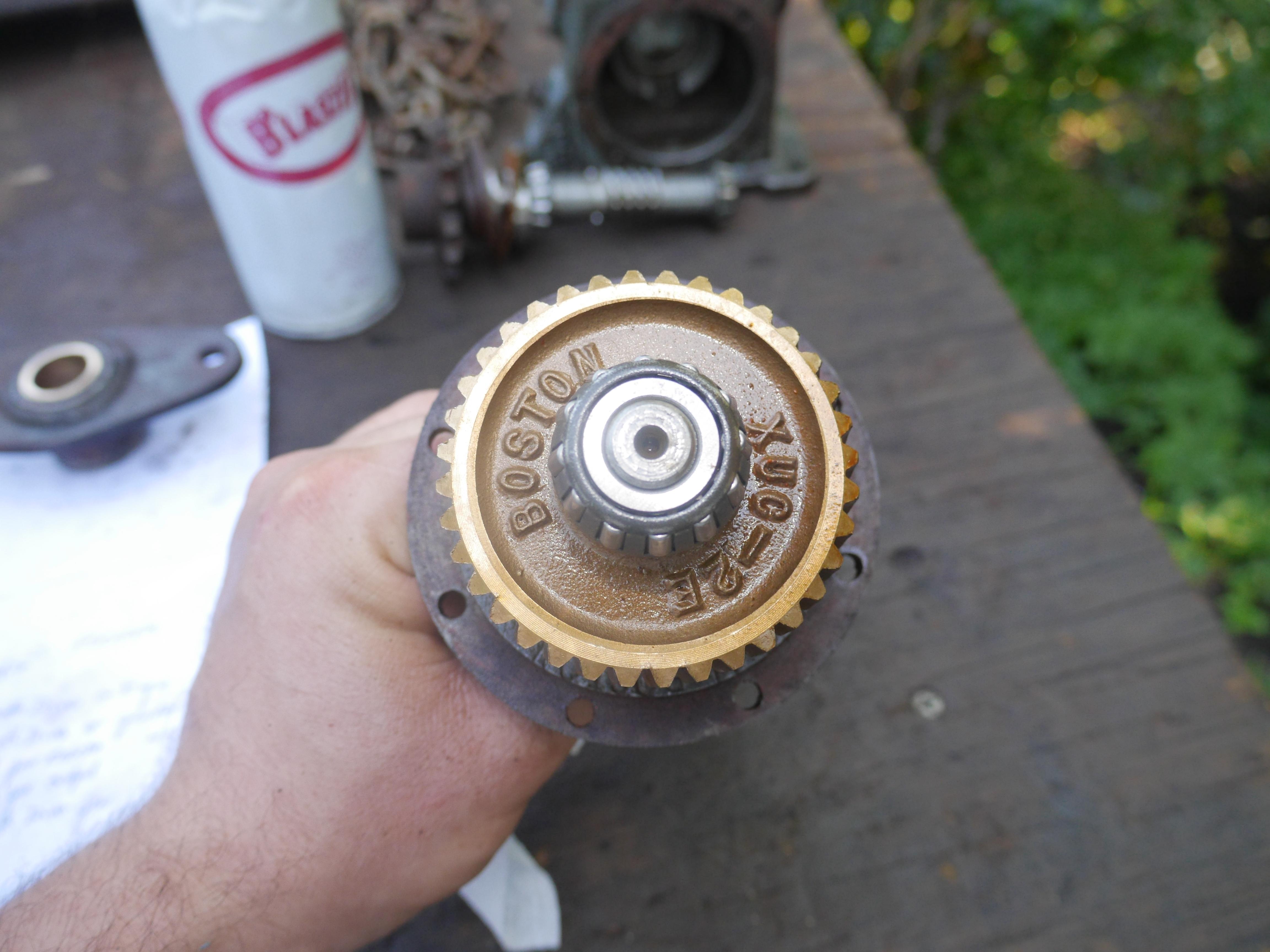
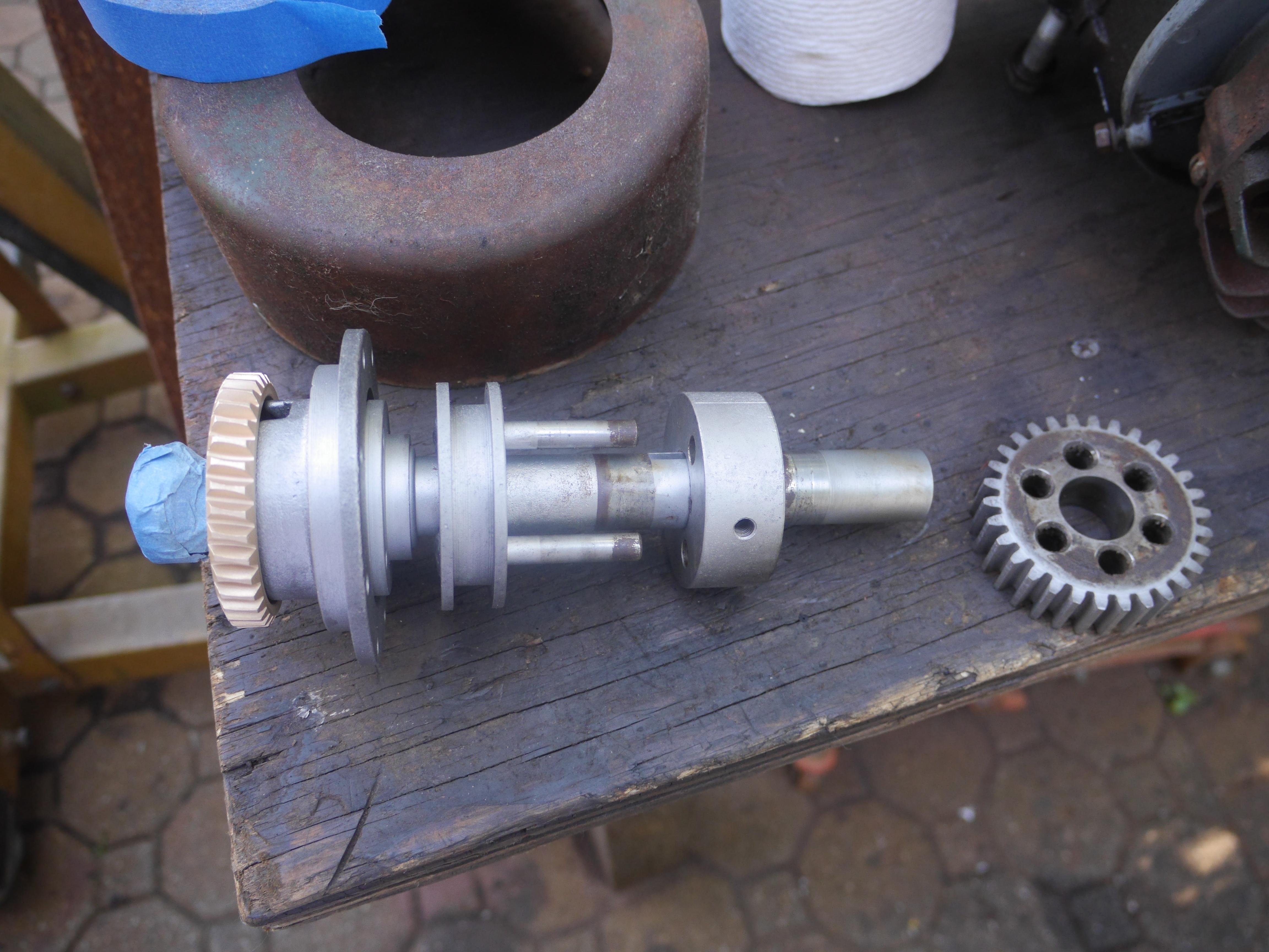
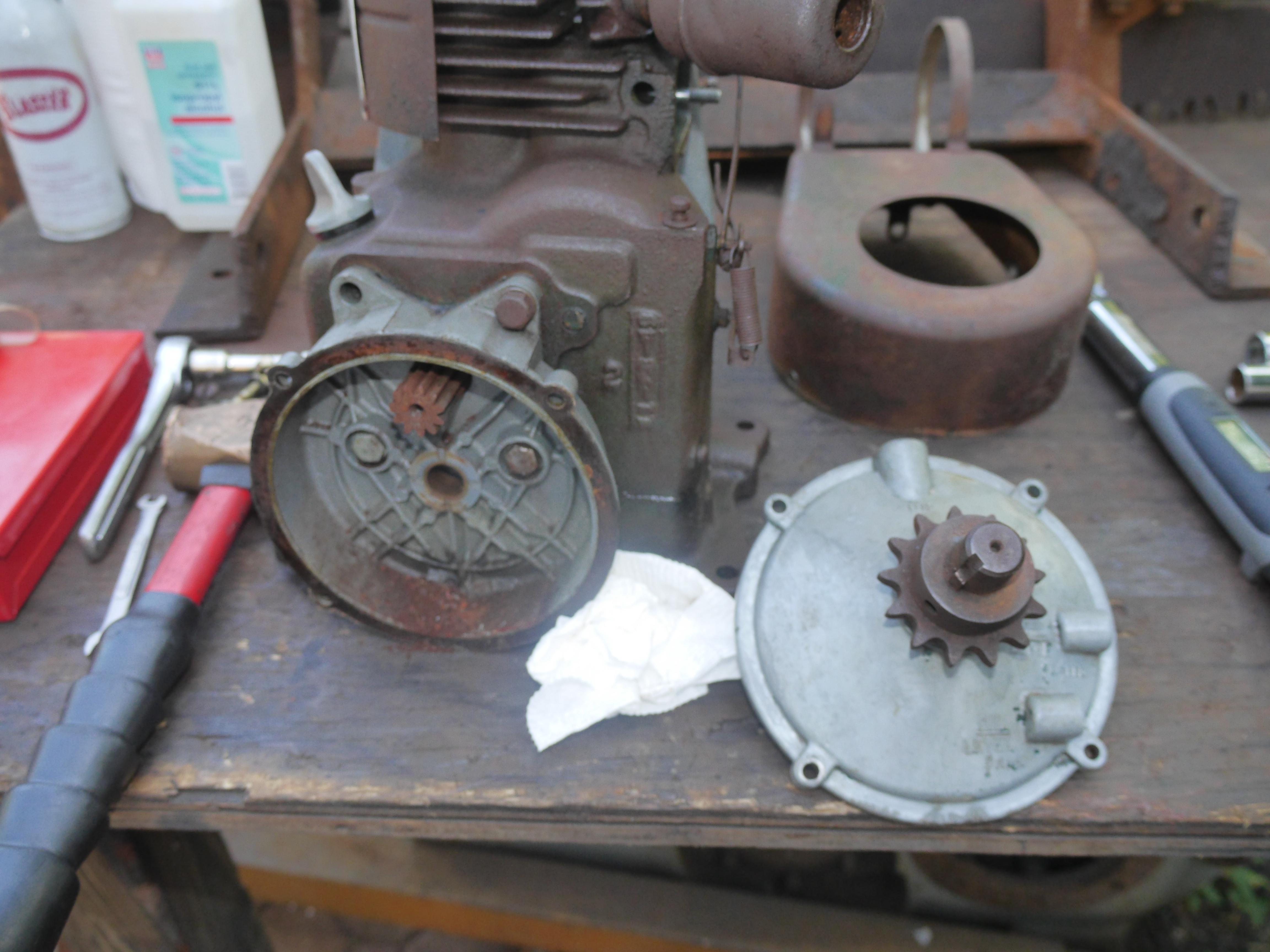
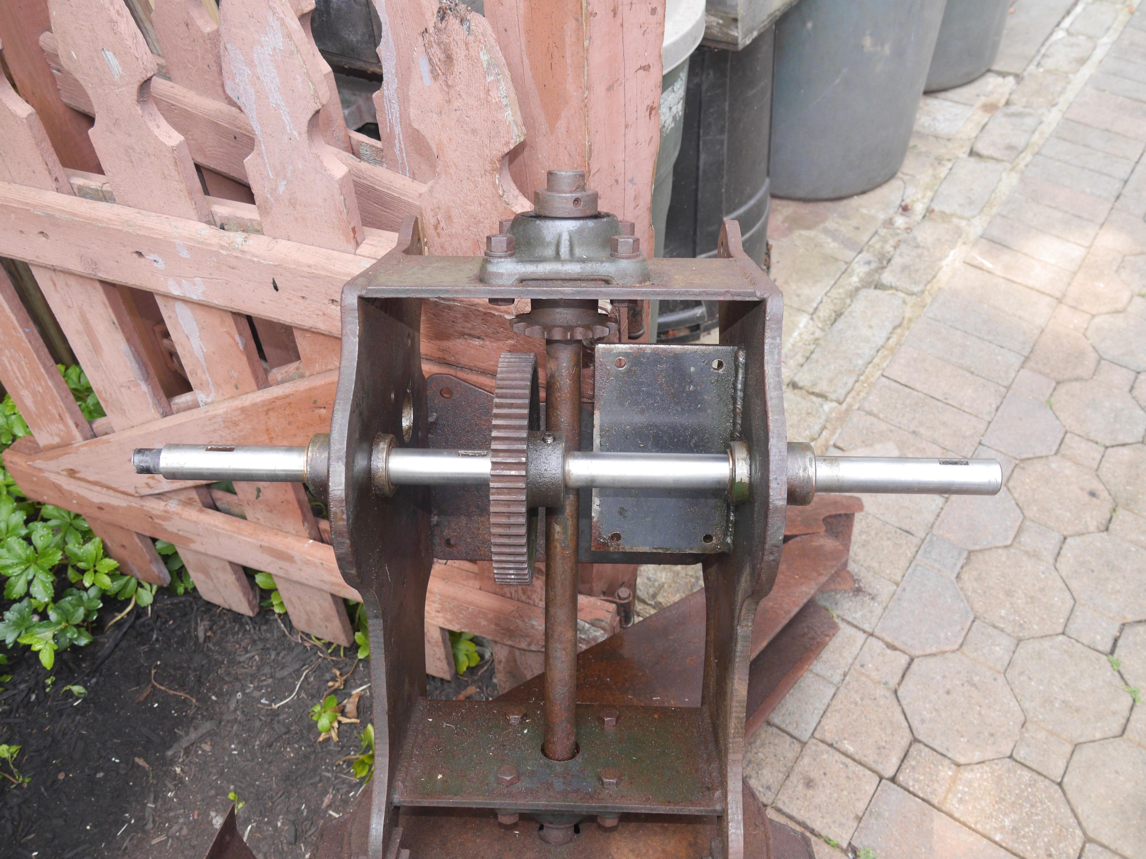
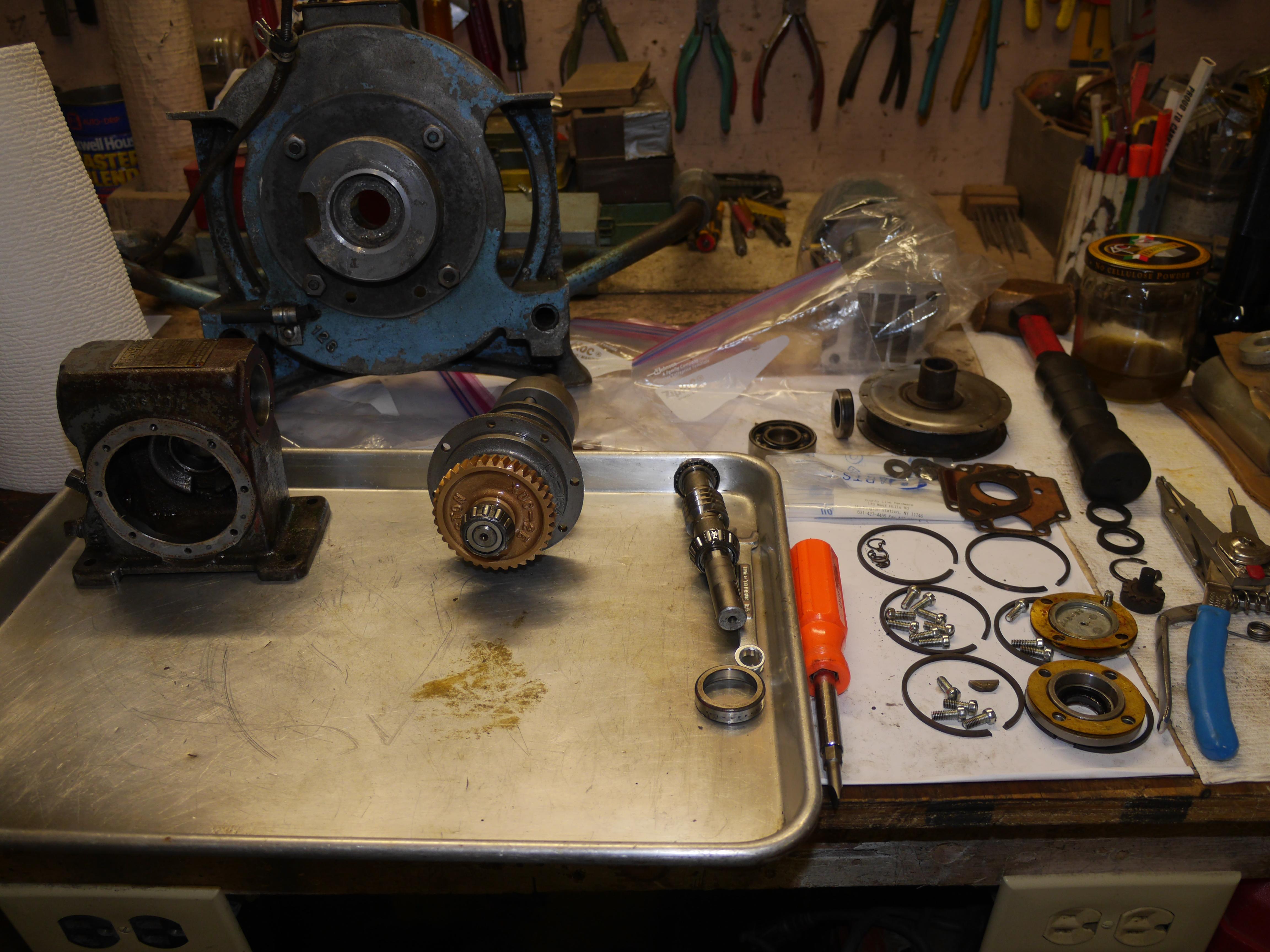
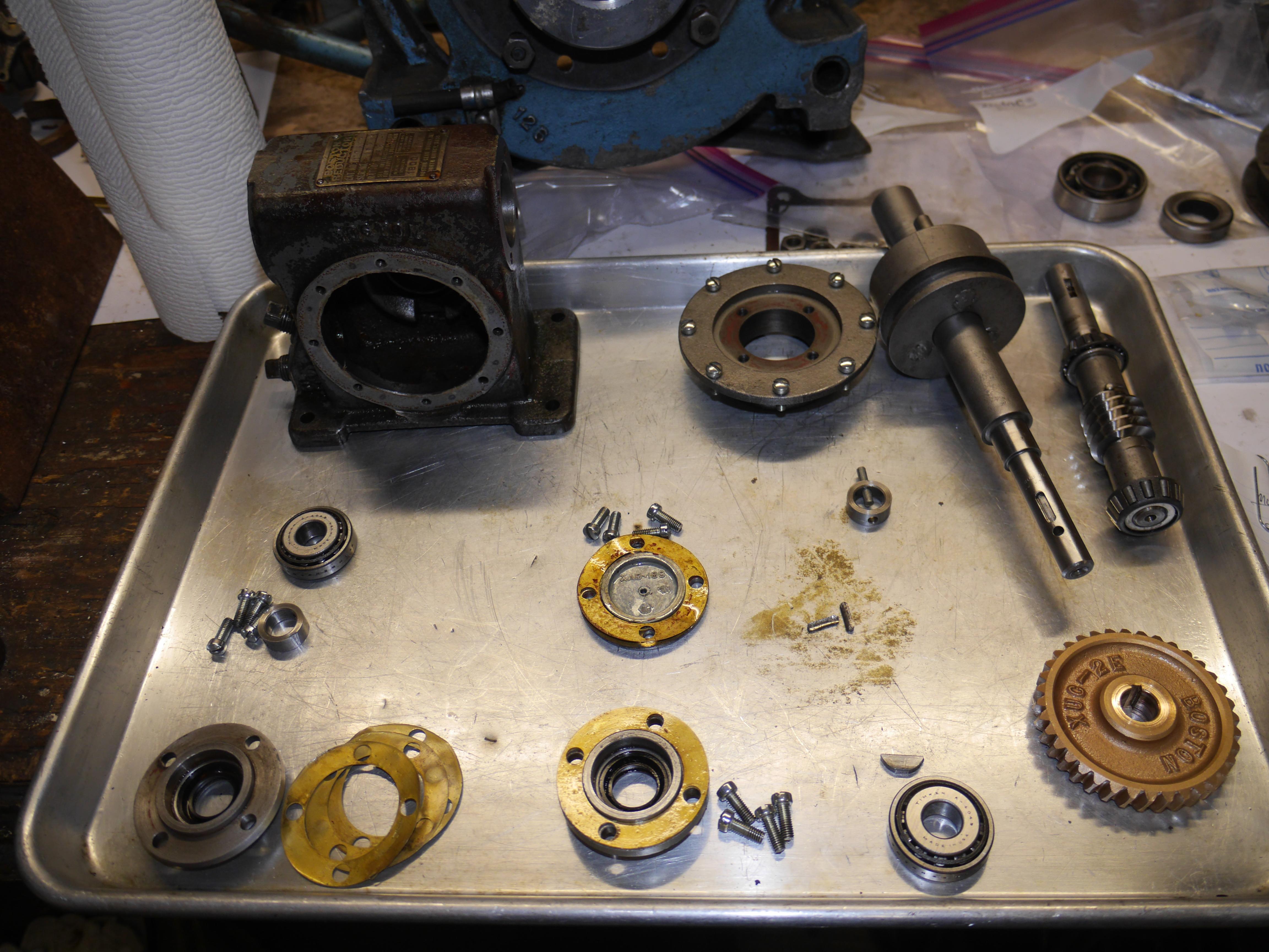
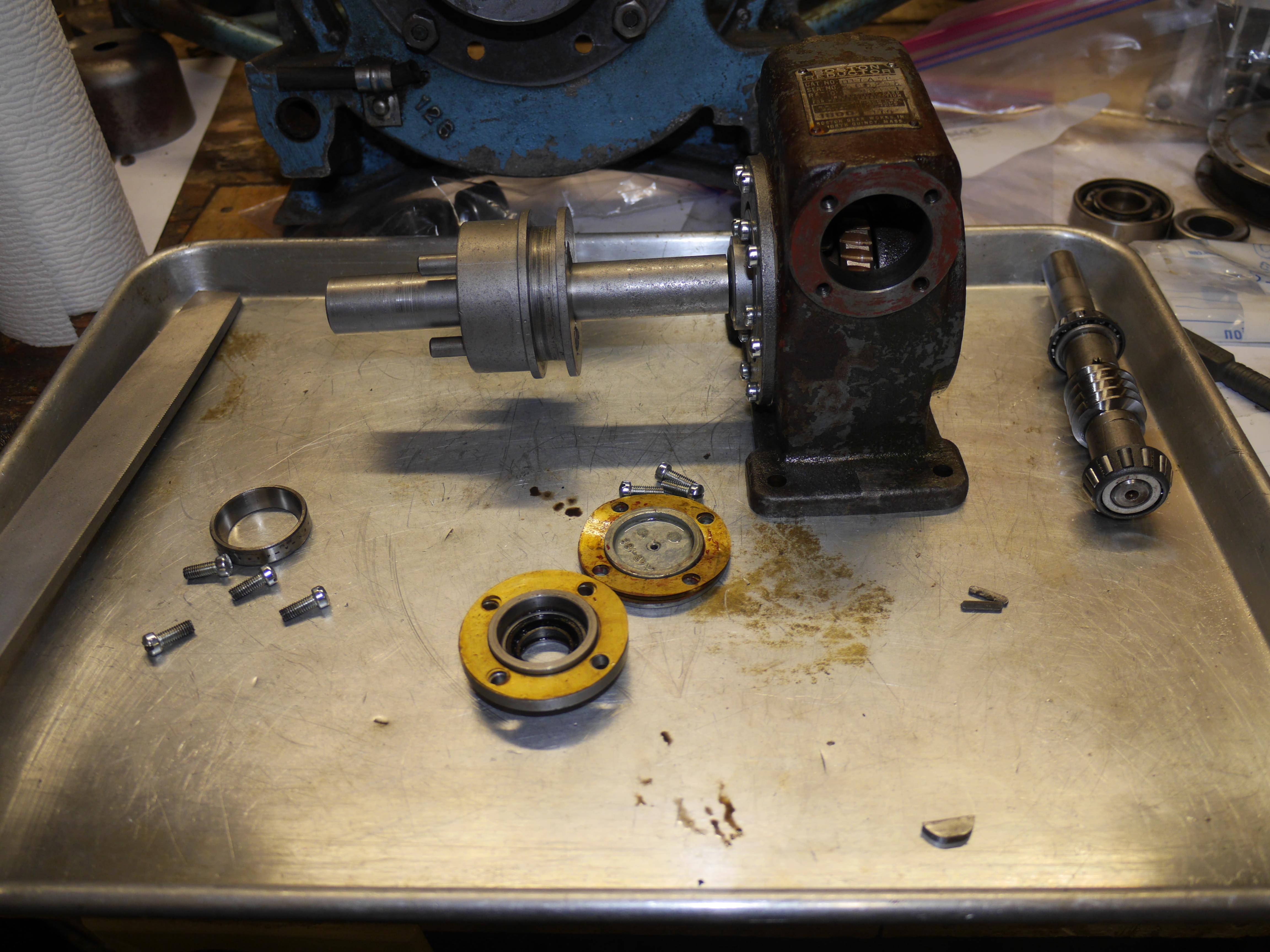
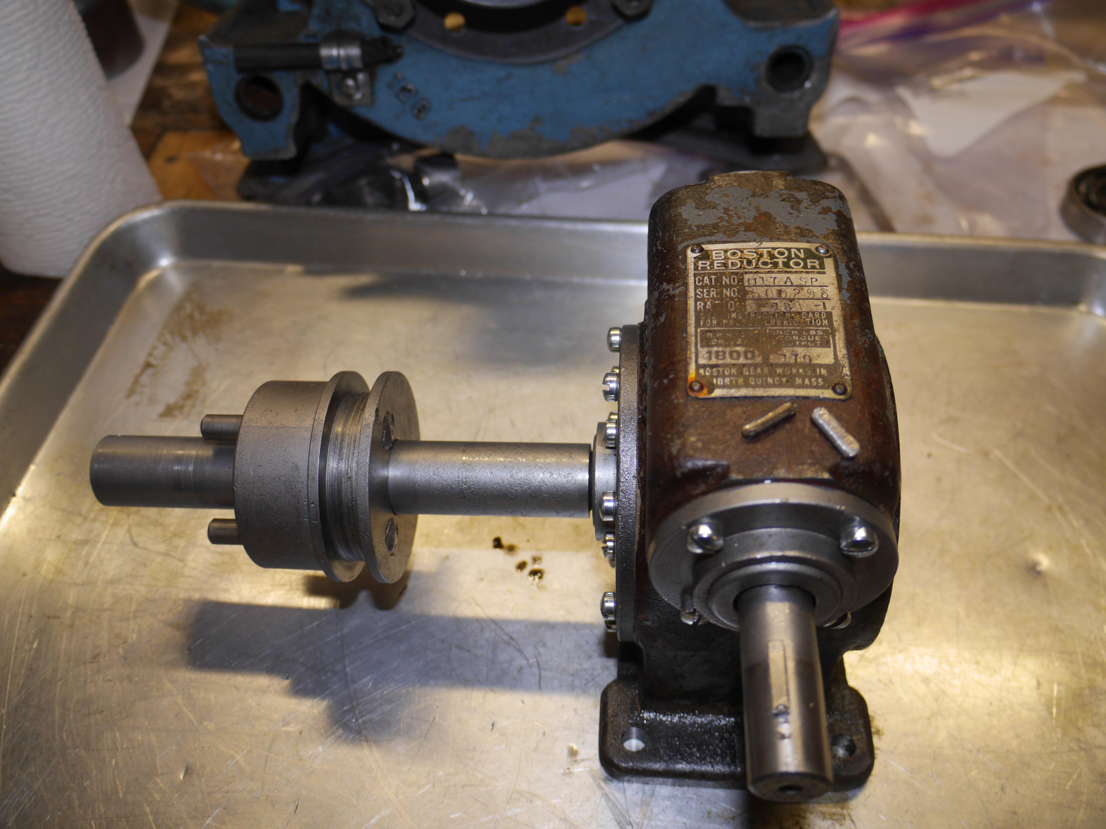
As with any new acquisition, the first step is usually to power wash and liberally soak the item in penetrating oil. There was no major dirt on this machine, just rust everywhere. After soaking the machine down with penetrating oil every day for a week, I began working on it. I initially wanted to figure out why the transmission was all apart. Removing the output shaft of the transmission was no problem since all of the work was already done for me. The question was why it was taken apart, and then what is missing from it? I unbolted the case for the transmission from the snow thrower, and discovered that the worm gear transmission was made by Boston Reductor. Some quick research showed that Boston Reductor moved their manufacturing to India. Good thing that this machine is old enough that the transmission was made in Boston Massachusetts. When I removed the transmission and looked at the input shaft, I damn near fainted. I could not believe how nice and clean it was. The worm shaft was made of stainless steel, and the worm wheel was made of bronze.
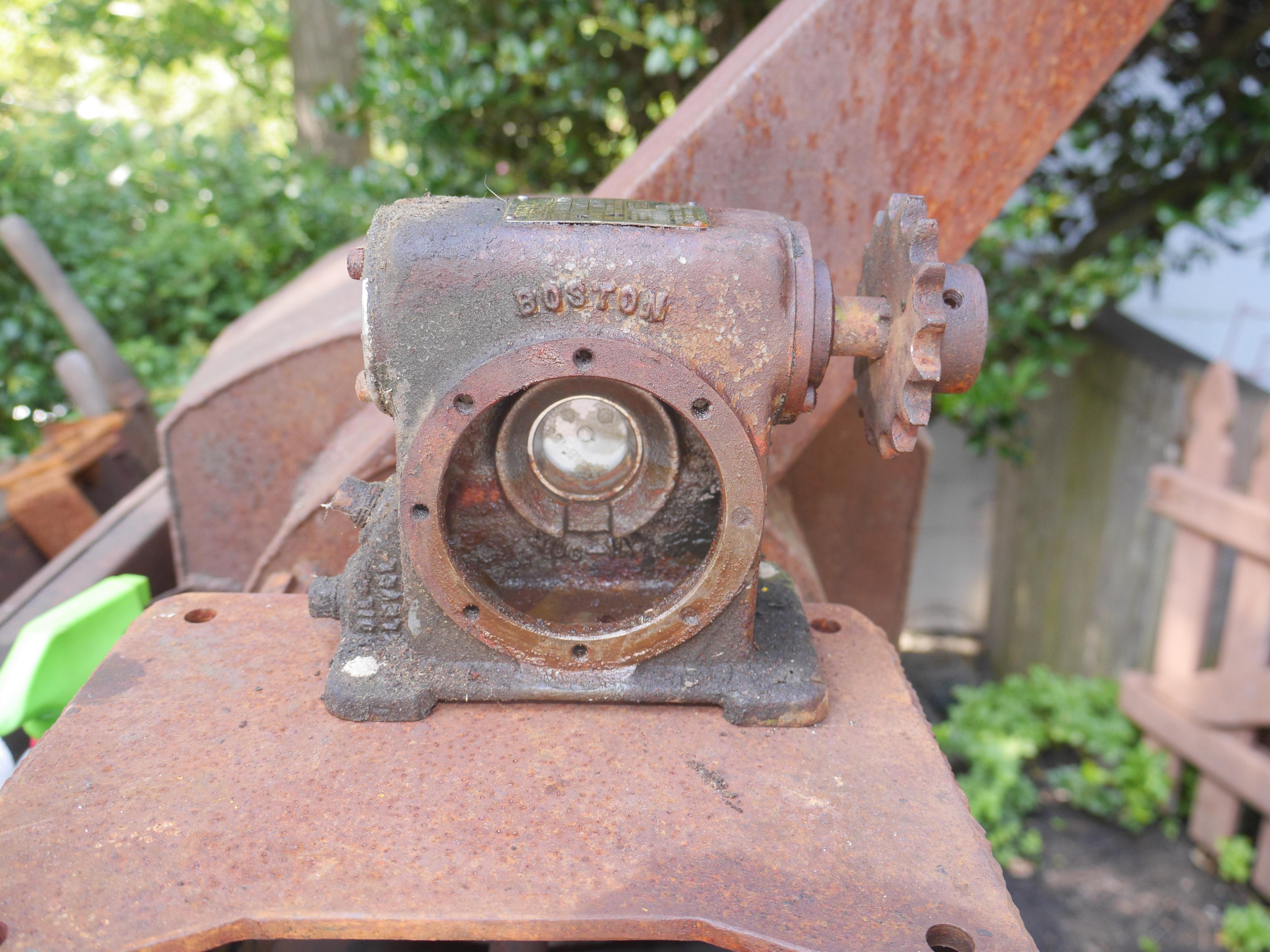
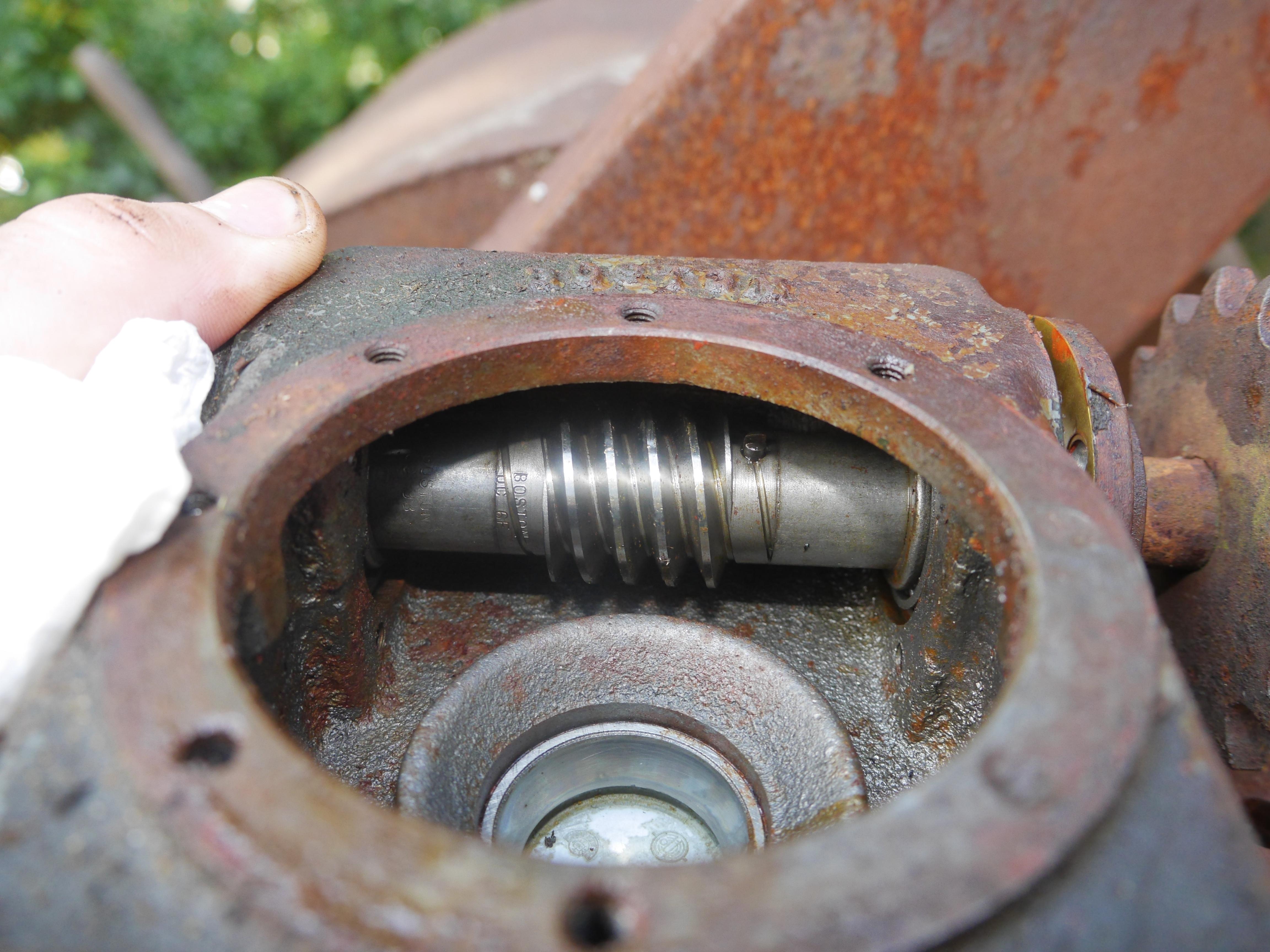

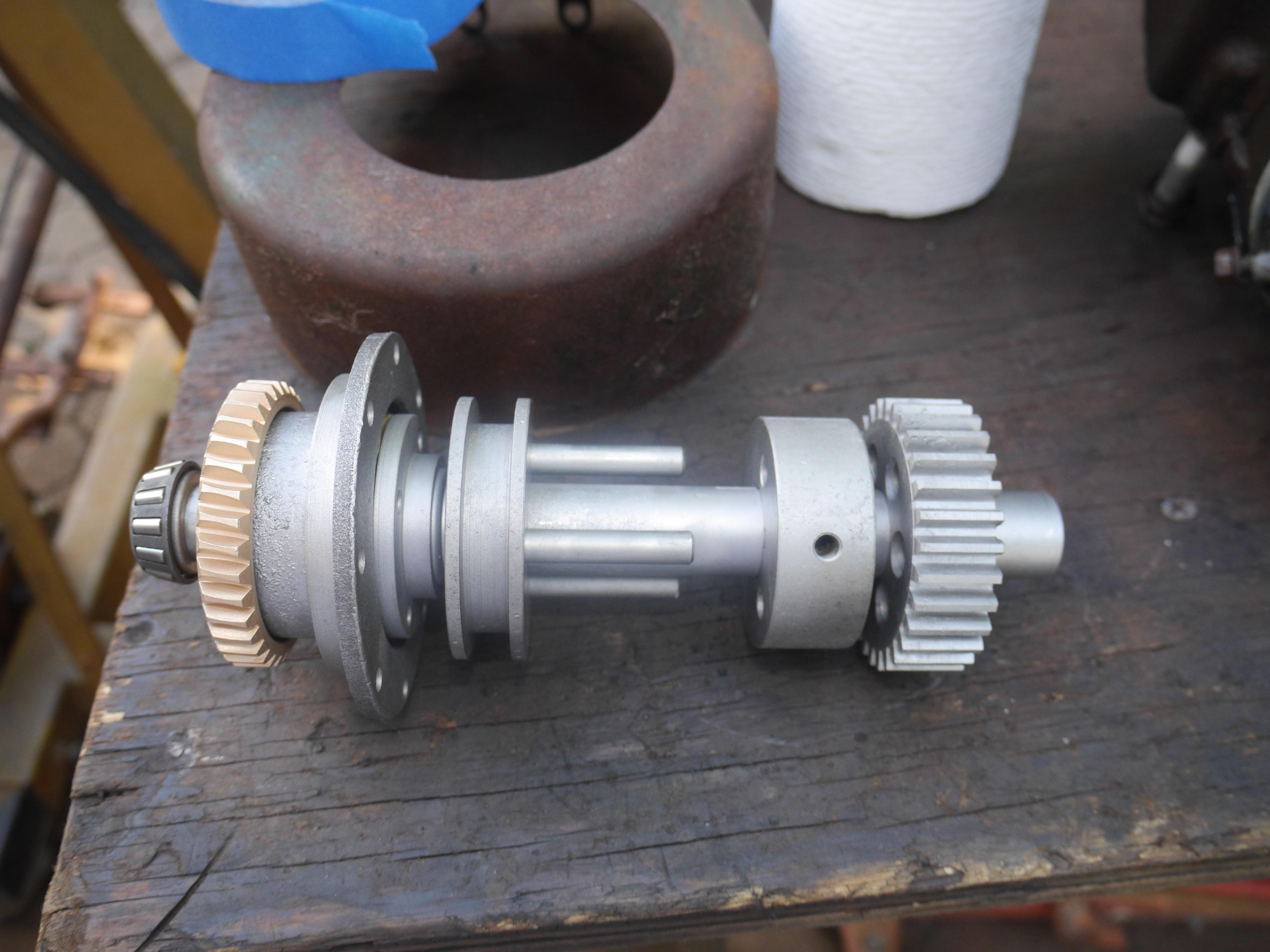
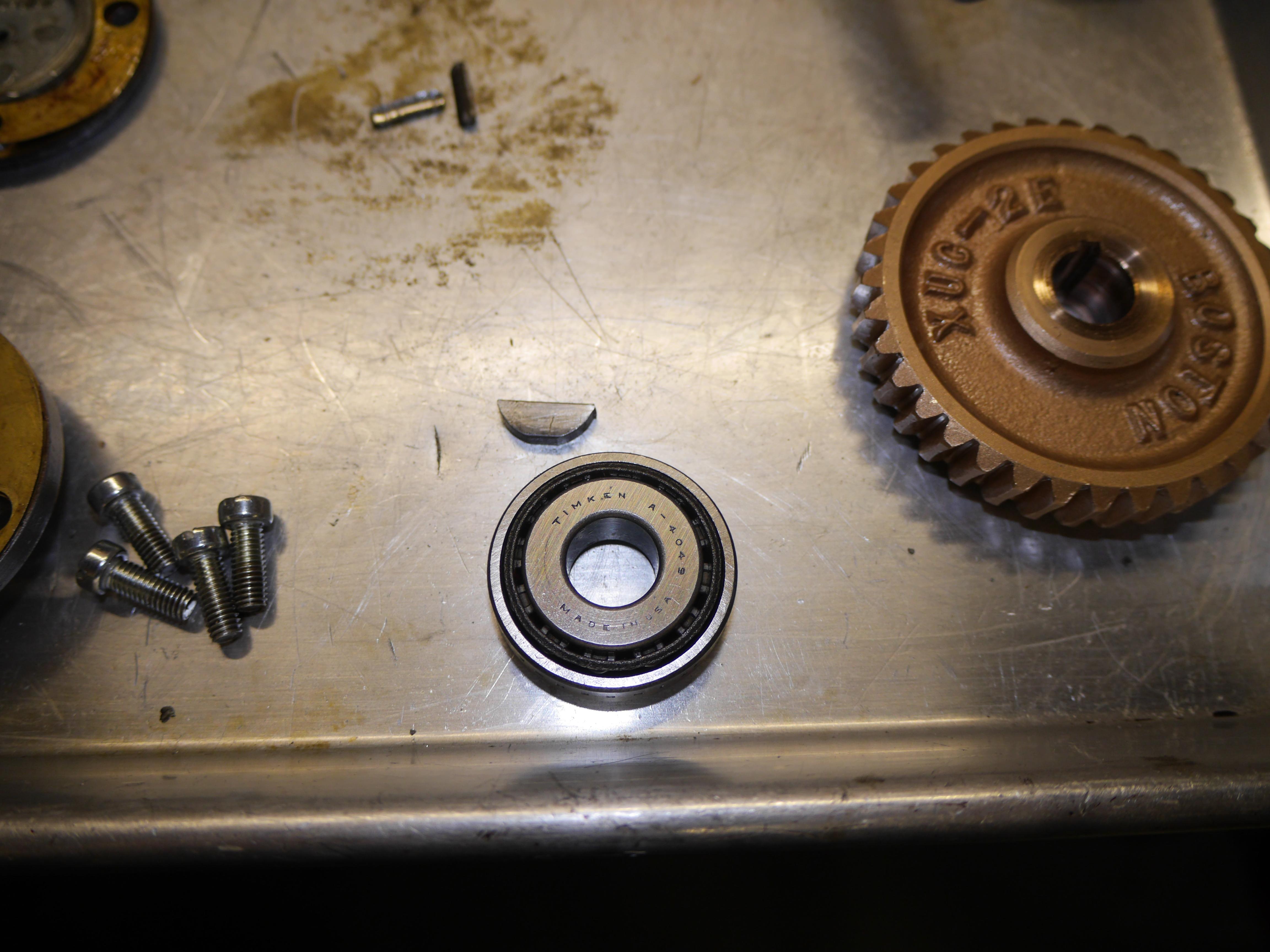
It is evident that this transmission was original to the machine as you can see how much pride the manufacturer took in casting their name into all of the components. You just do not see that anymore. To my surprise I was able to get the original Timken tapered roller bearings turning without too much trouble. Some penetrating oil was all that was really needed. I removed the stainless steel input shaft and checked its fit against the bronze worm wheel. It was a miracle that neither the worm or worm wheel showed any appreciable wear considering the age of this machine and how the transmission has been sitting open to the elements for years.
Design Decisions
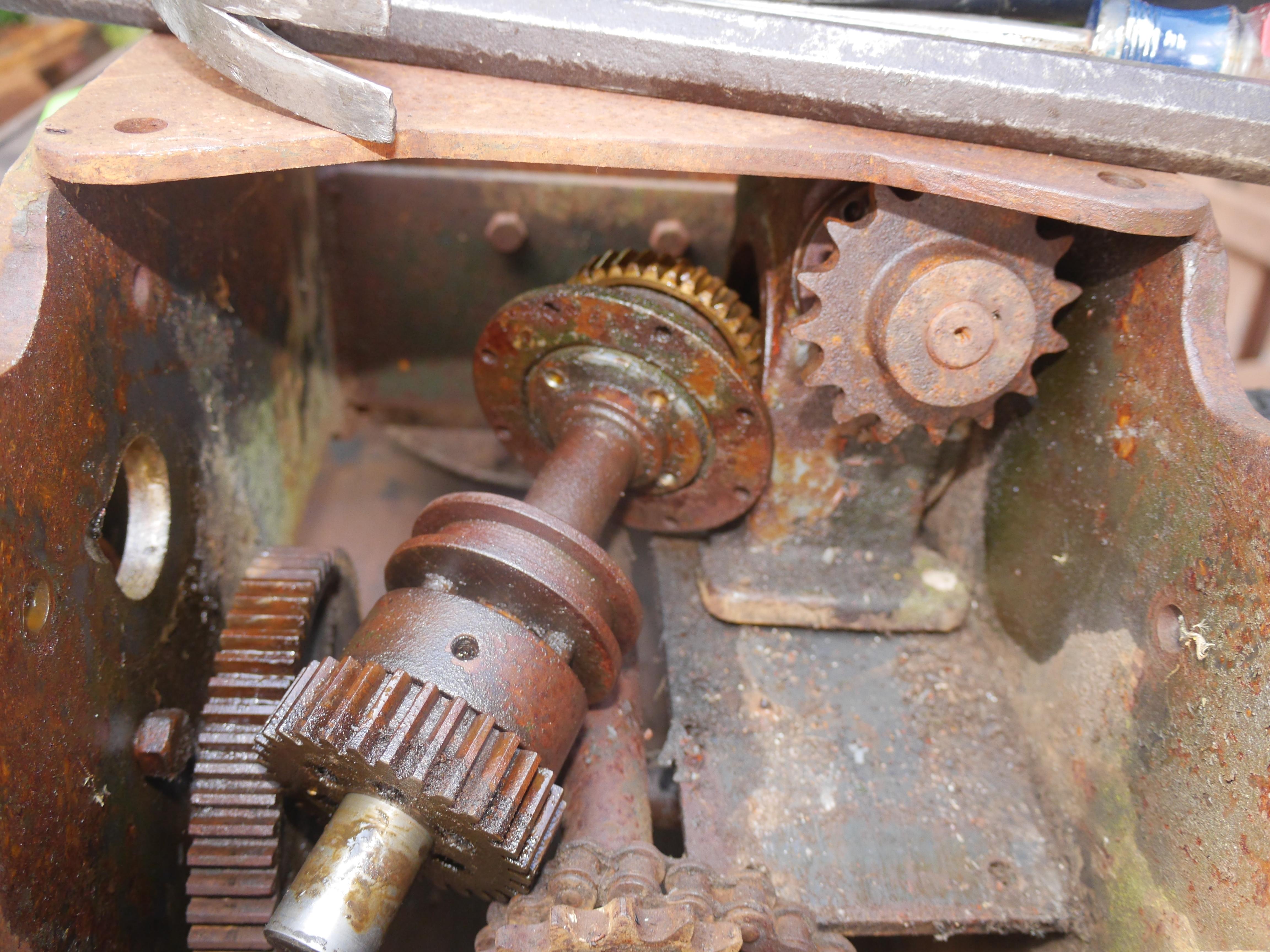
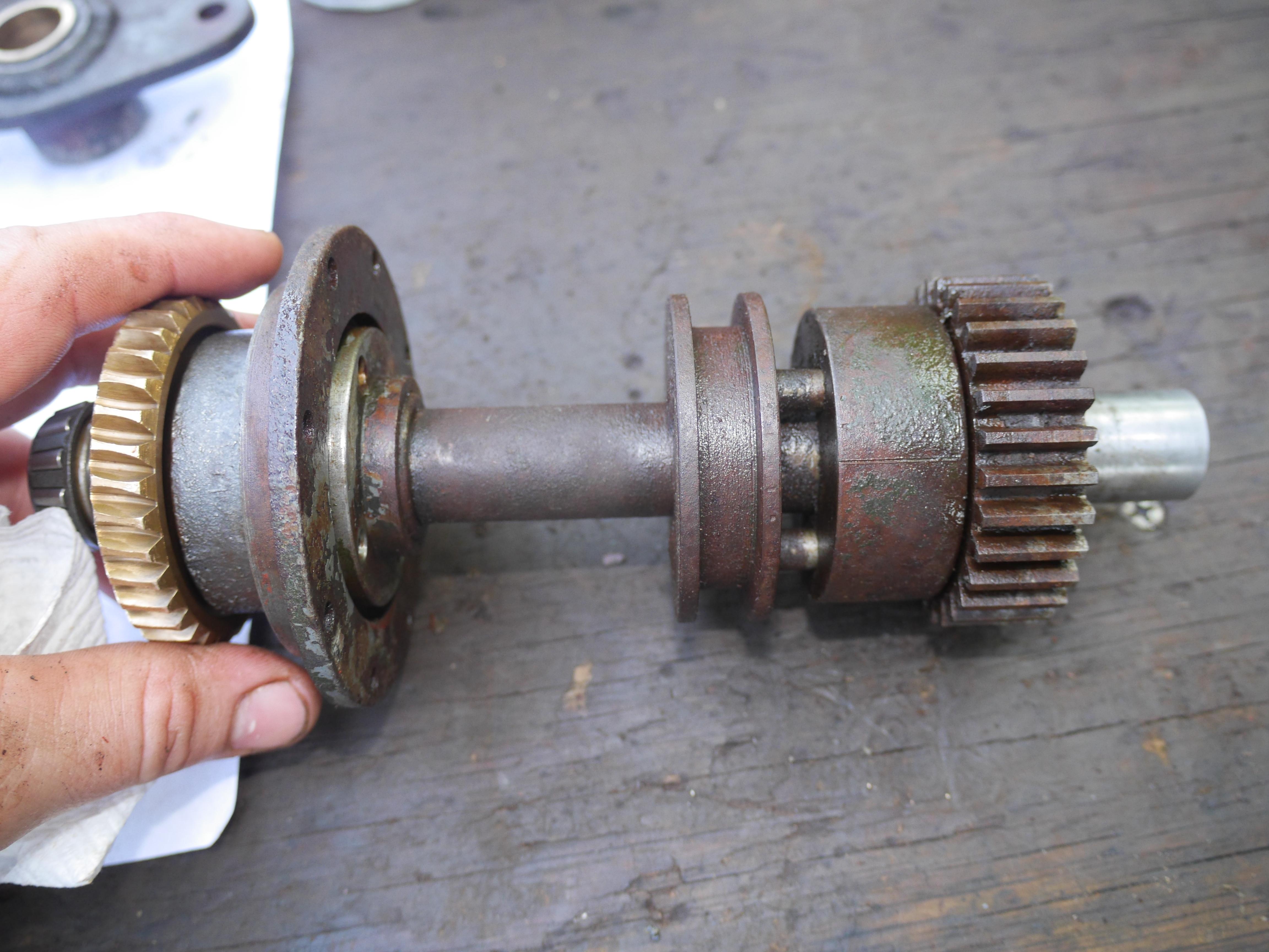
Because the rest of the output shaft was steel, everything was rusted in place. I had no choice but to put the output shaft in my blast cabinet. Bead blasting removes any rust and scale on a surface allowing the penetrating oil to really get into any crevices to help loosen the rust bond. Bead blasting and soaking in penetrating oil allowed me to move the sliding clutch for the first time in years. You can see where the clutch dog has been sitting for years as indicated by the rust banding. Moving the sliding clutch dog also released the output shaft gear which was great.
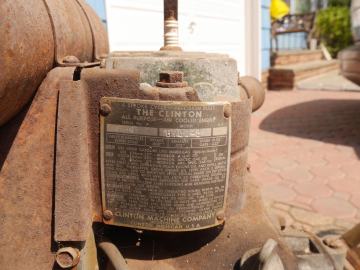
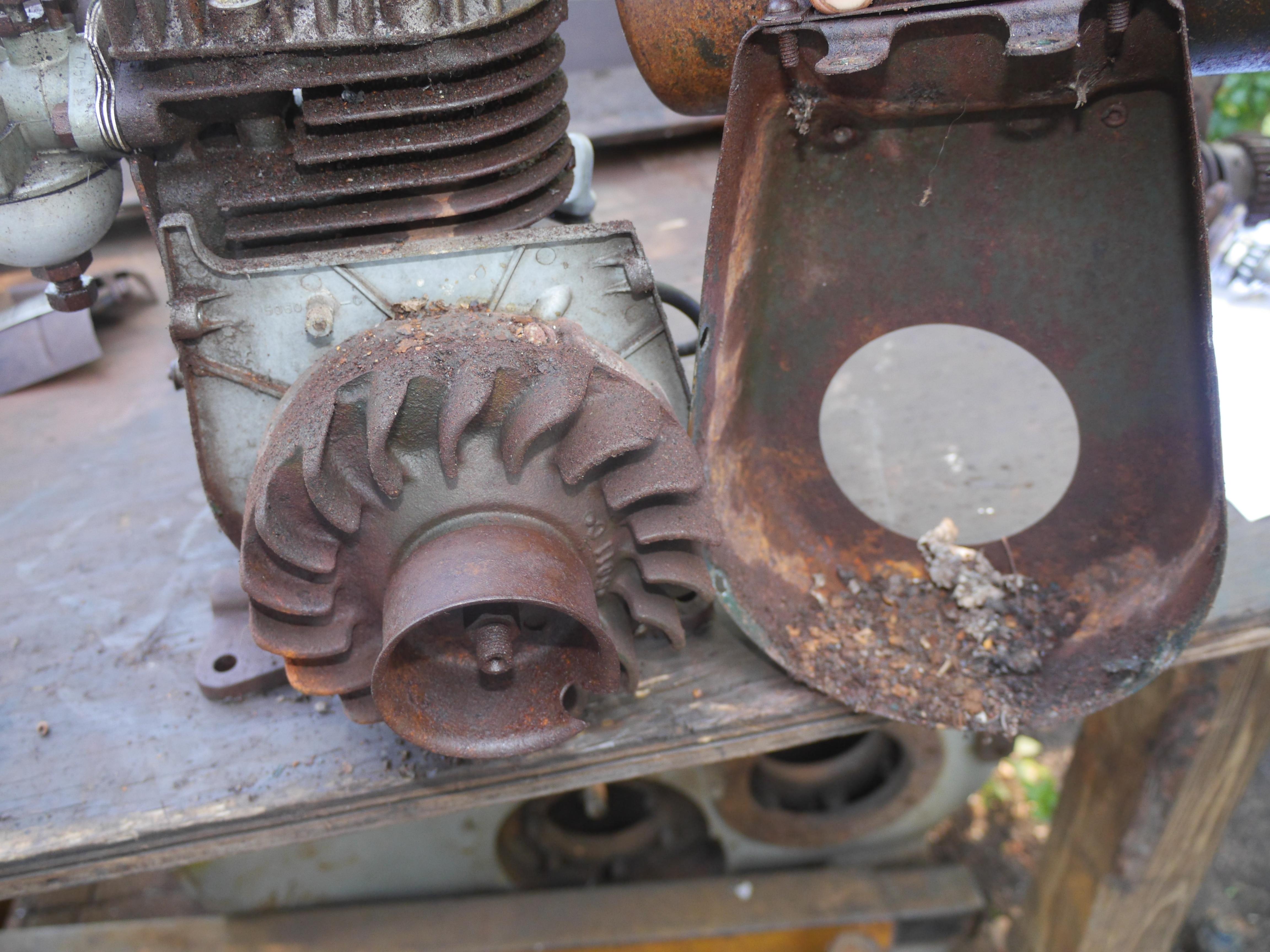
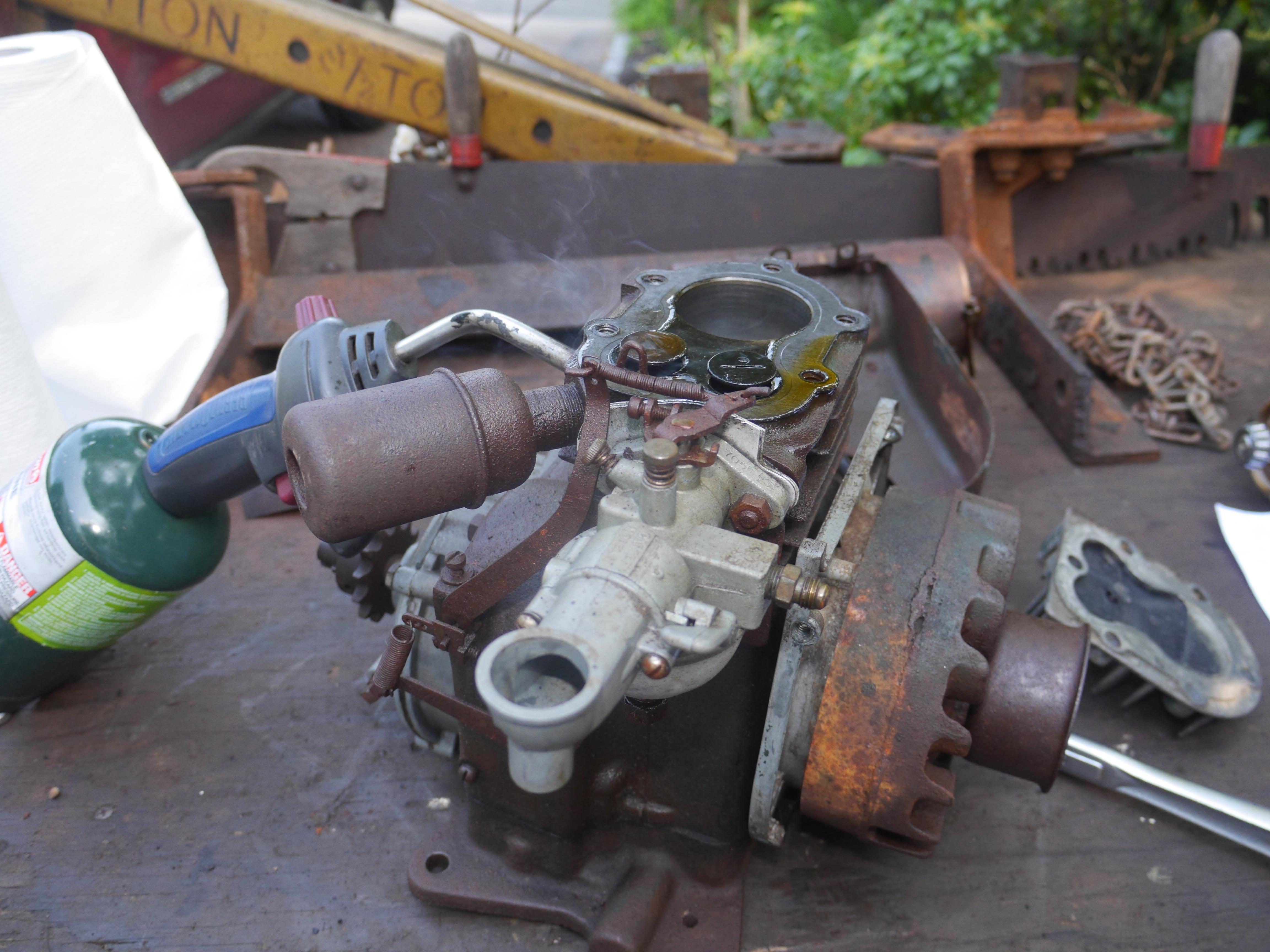
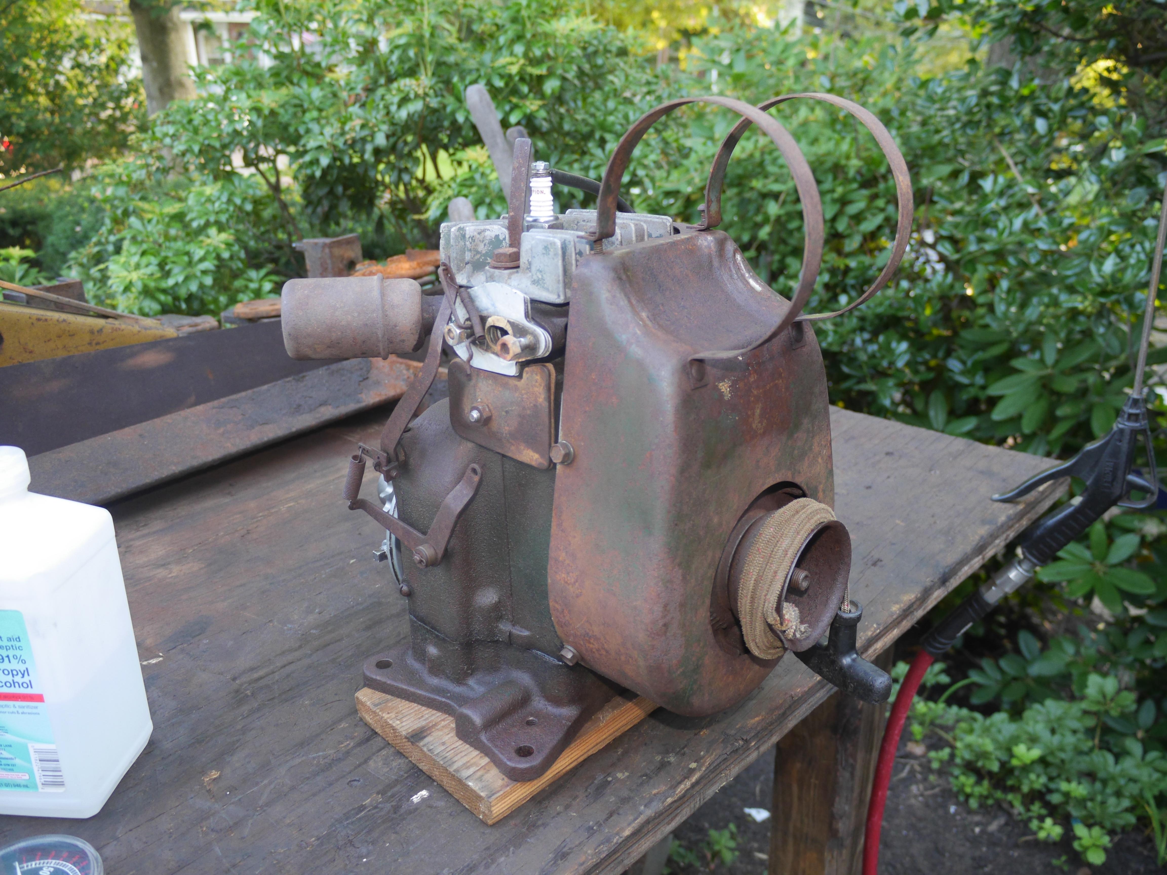
With good success coming from the transmission, I decided to see if my luck would carry on with the engine. As you can see it was quite a mess. While the engine was soaking in penetrating oil, I grabbed a spare Wisconsin ABN engine and sat it down on the engine mounting plate. I was surprised to see that the bolt holes did not line up with the Wisconsin engine. I grabbed a smaller model AA Wisconsin engine and even that did not line up with the bolt pattern drilled into the plate on this snow thrower. I realized that against all odds, the Clinton was the original engine for this machine. Maxim collectors like myself have never heard of a machine with anything other than a Wisconsin engine. Realizing that I had something very special, I took every precaution necessary to try and save the original Clinton engine.

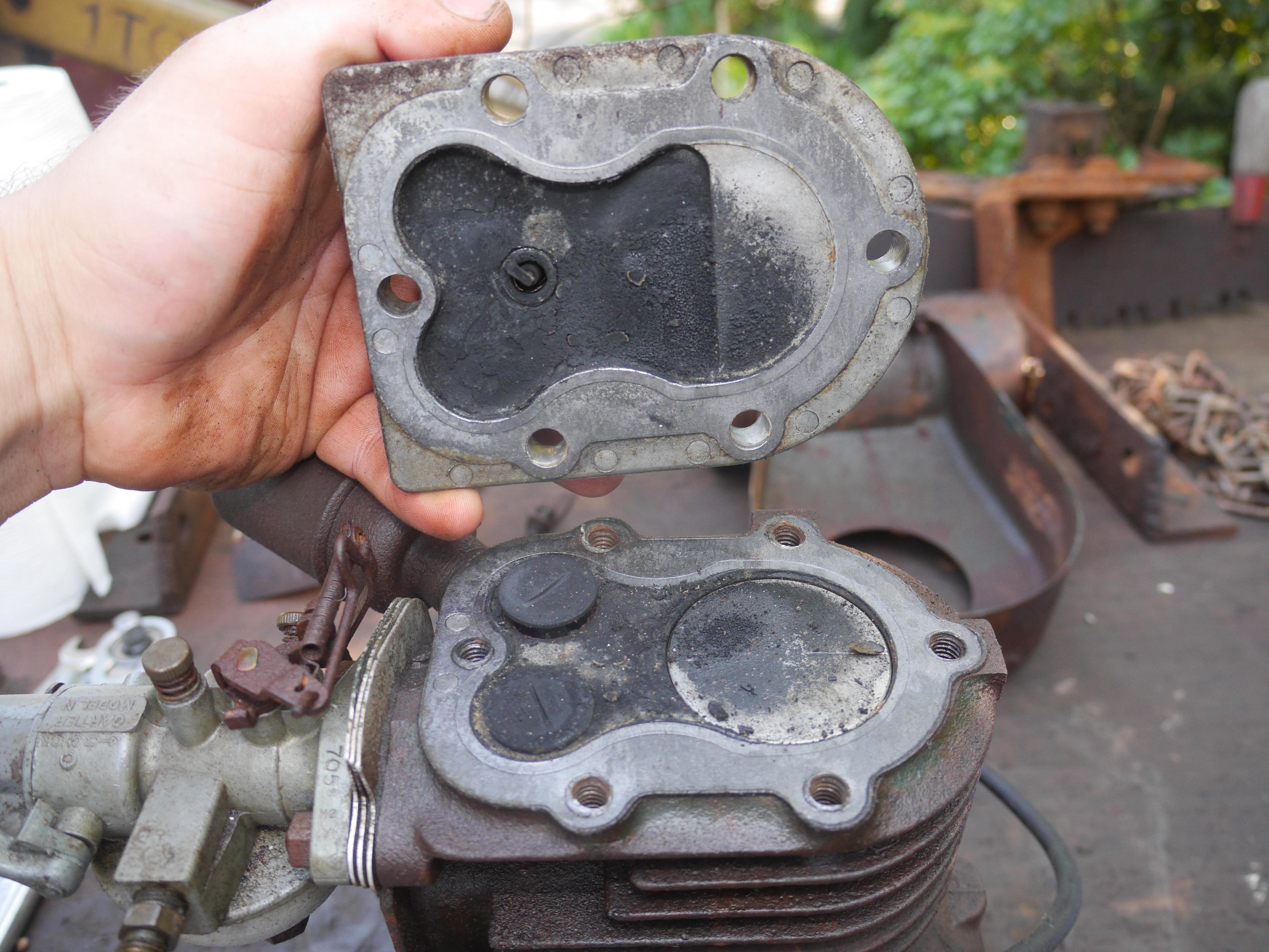
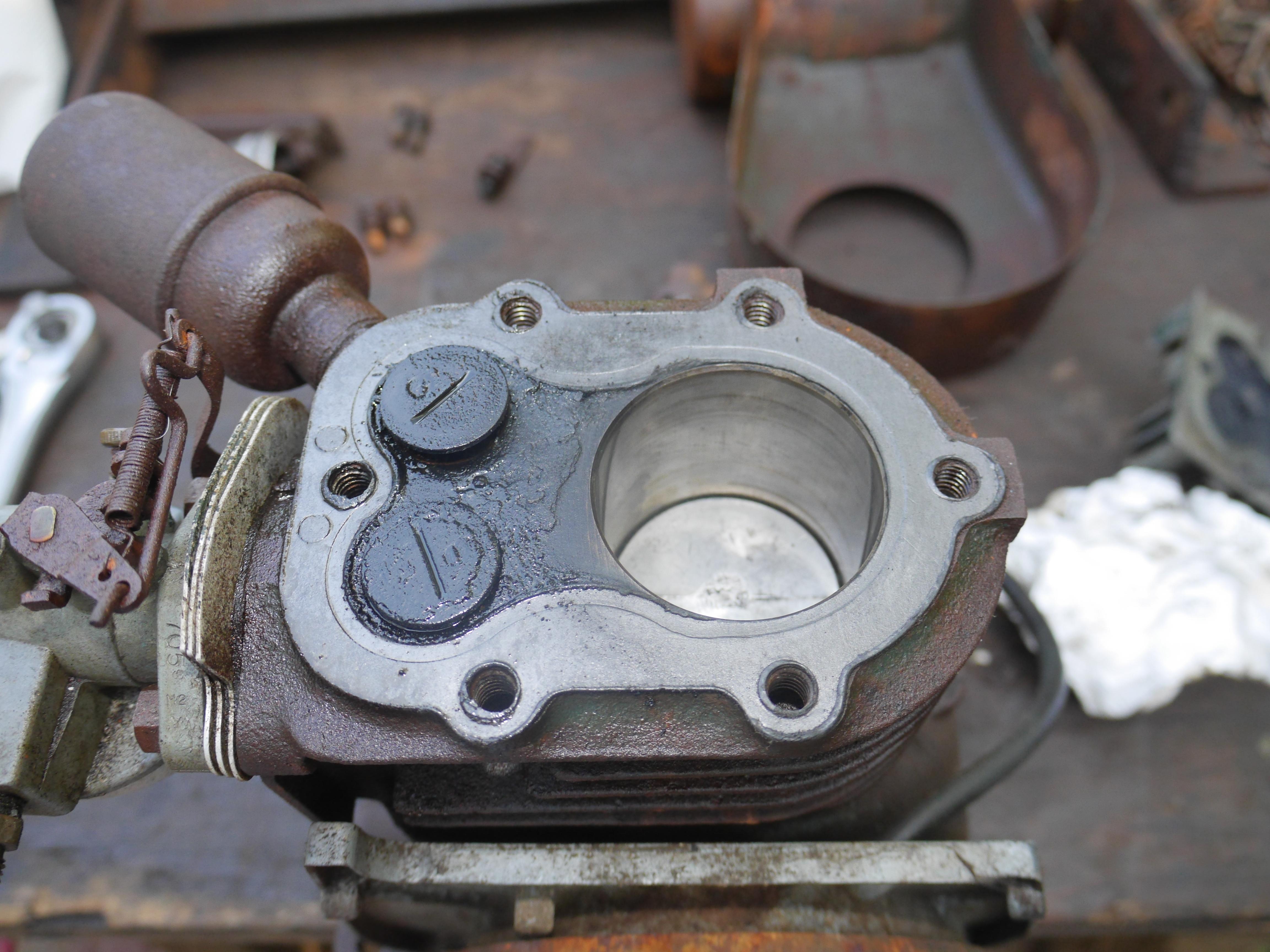
I removed the blower shroud and fuel tank from the engine, revealing a pile of crushed up acorns, rust and muddauber nests. Pulling the cylinder head revealed that this engine did not have very much run time on it. The piston and cylinder head were surprisingly clean. After wiping the piston clean, a liberal amount of penetrating oil and a little bit of muscling the flywheel back and forth worked the engine free again. I was so relieved. The engine did not turn a whole 360*, but it turned about 300*. The exhaust valve was stuck in the middle position preventing the crankshaft from making a complete revolution. Some penetrating oil, a little bit of tapping with a rubber mallet to heed penetration, and some heat from a propane torch had the exhaust valve moving in about twenty minutes.
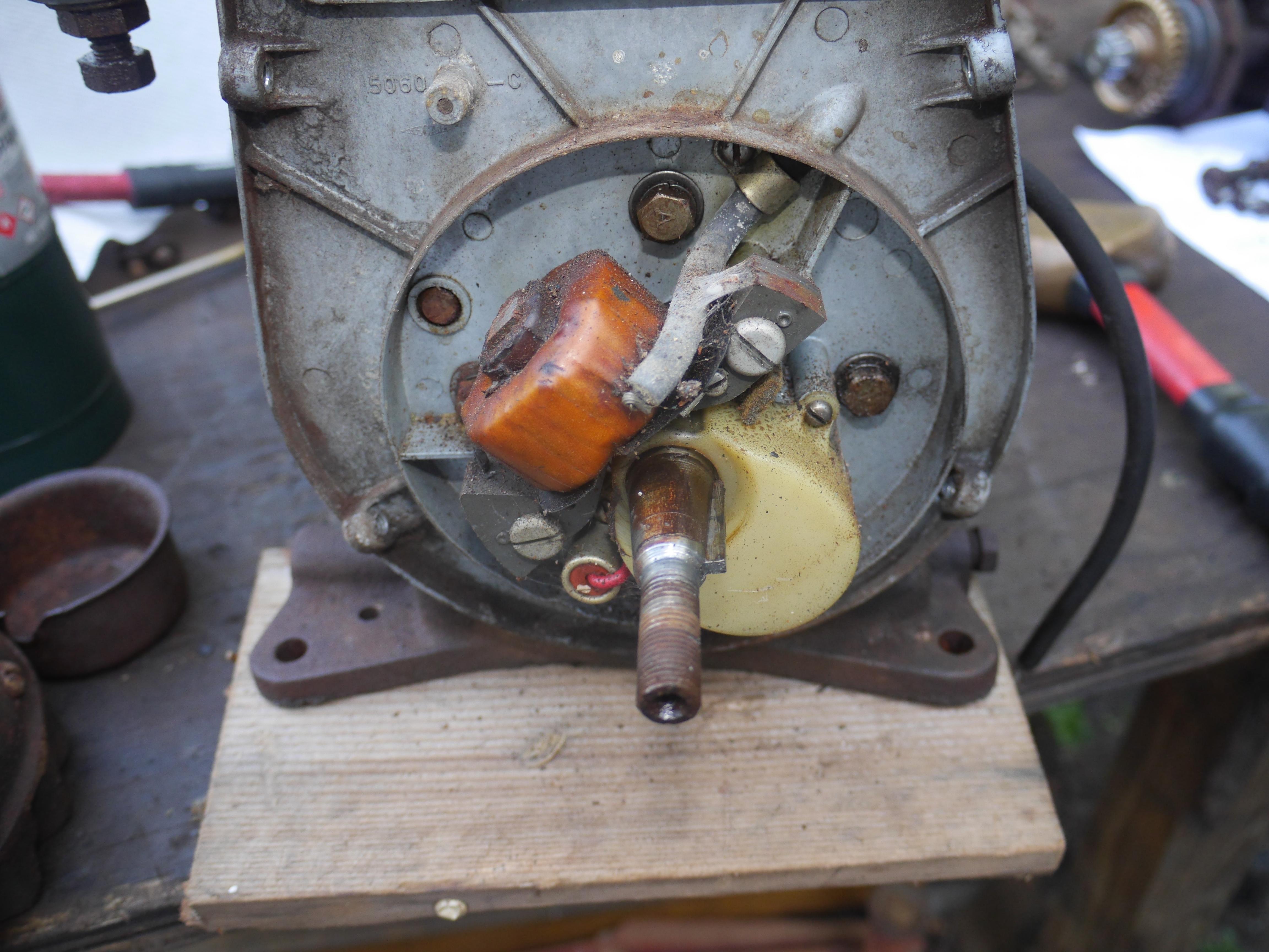
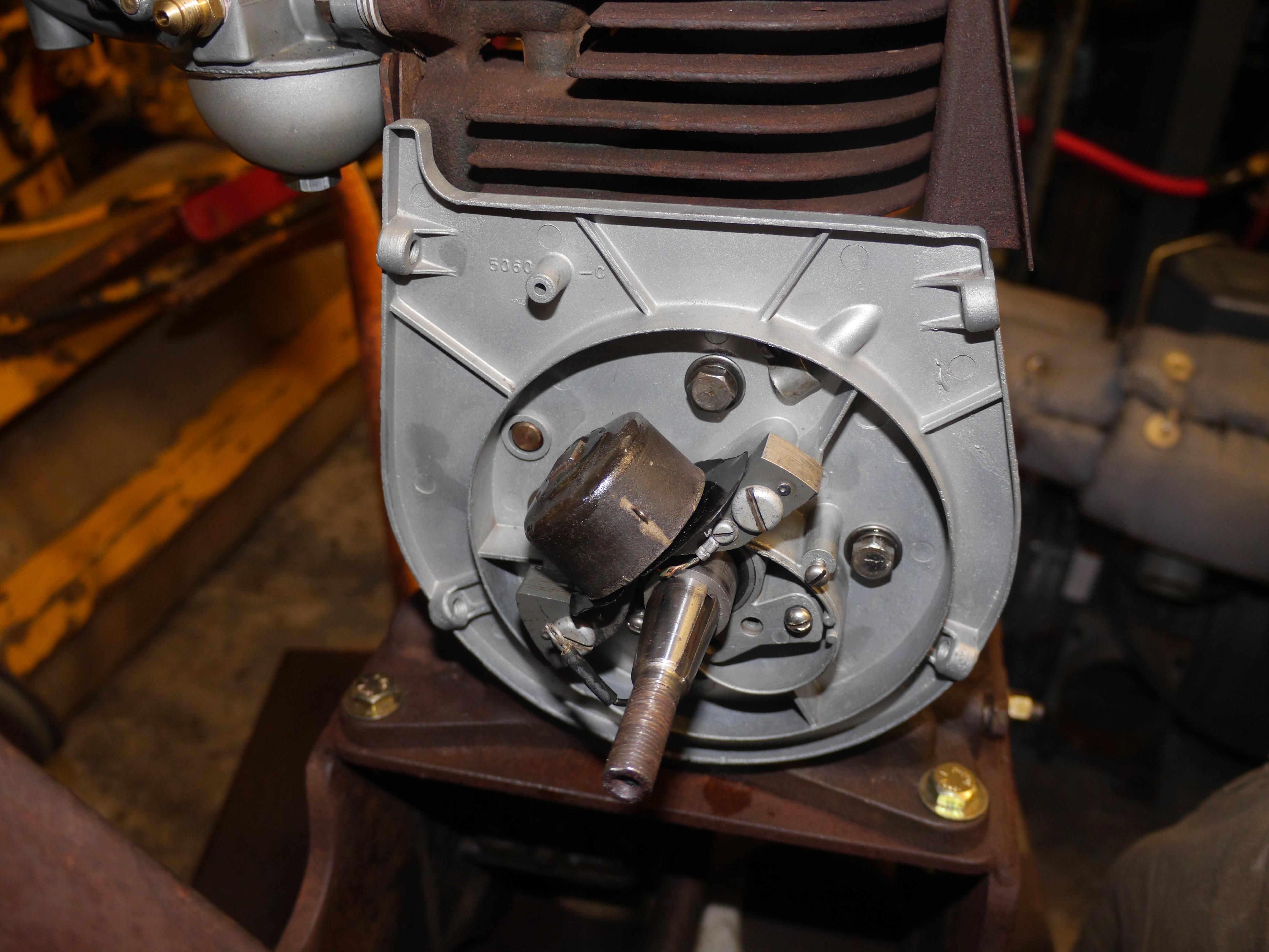
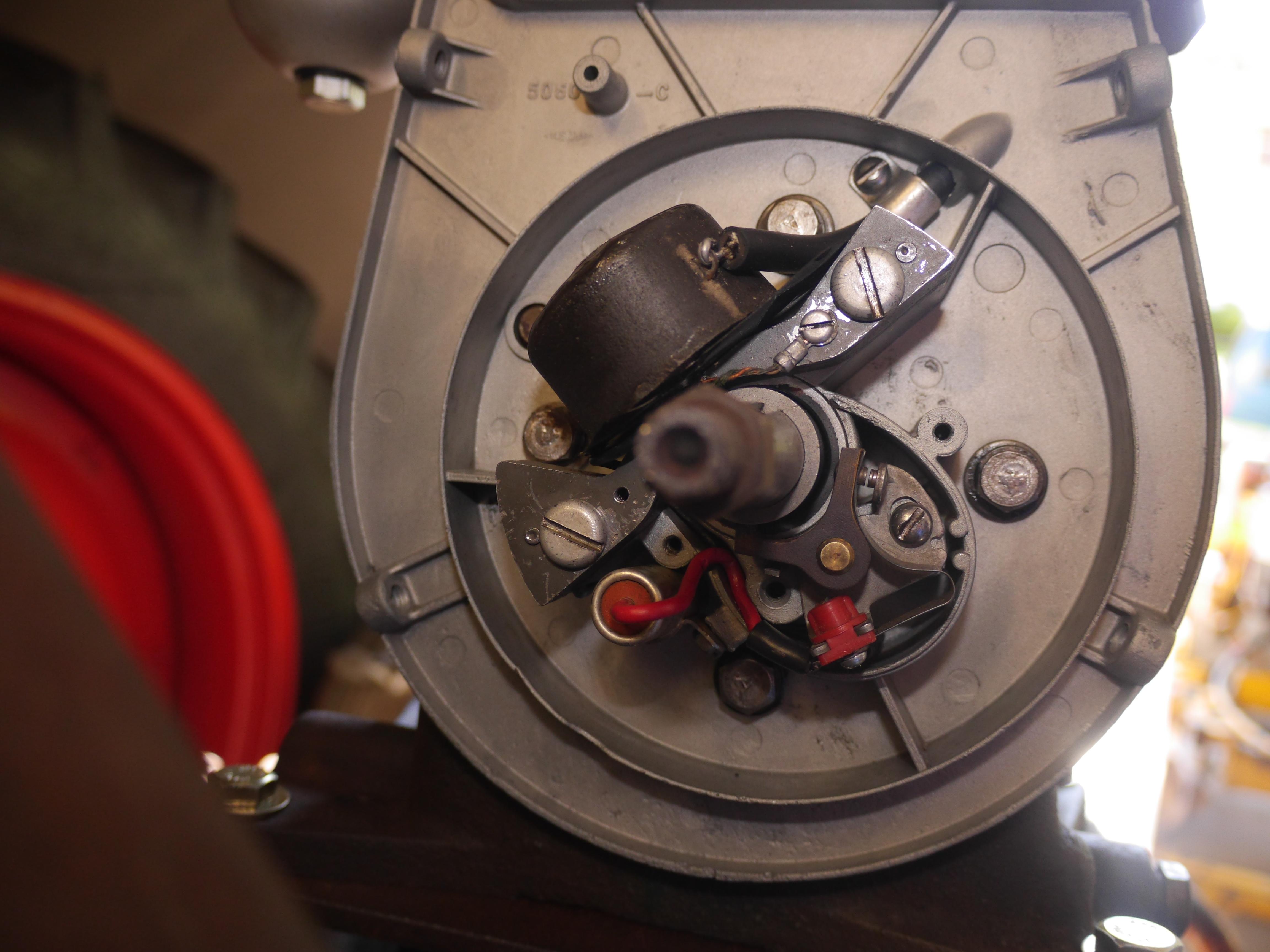
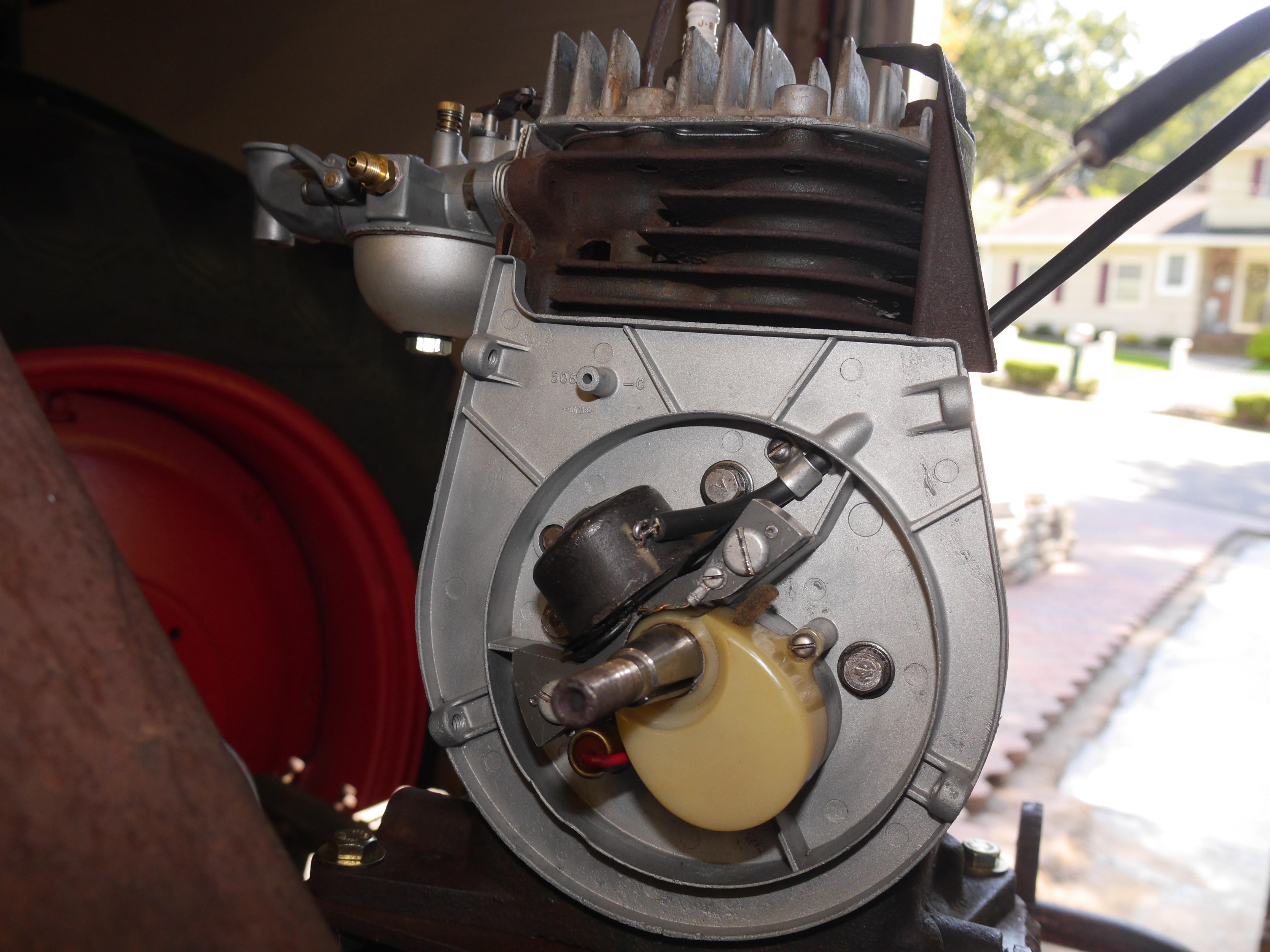
With the engine turning 360*, I decided that it was time to pull the flywheel and see why the engine had no spark. The inside of the flywheel was a bit rusty, and the coil laminations were rusty and dirty. The points were somewhat more protected from the elements behind the opaque plastic cover. The points were crusty and oxidized. When I went to clean up the tungsten points with an emery board, the plating literally fell off the copper lamination. I knew that I had to at the very least replace the points. Luckily the ignition system on this engine is REPCO and not the alternative Bendix Scintilla.


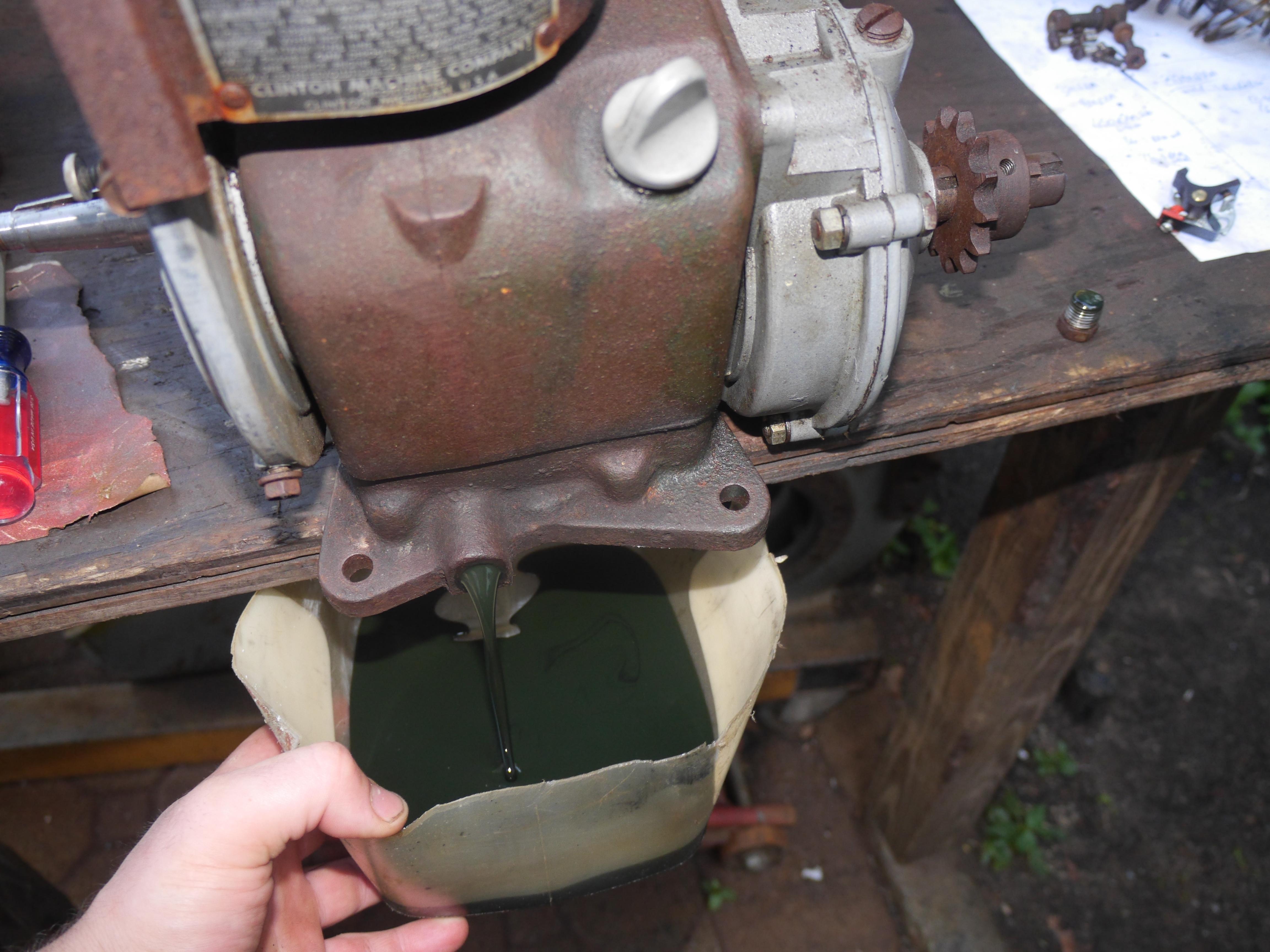
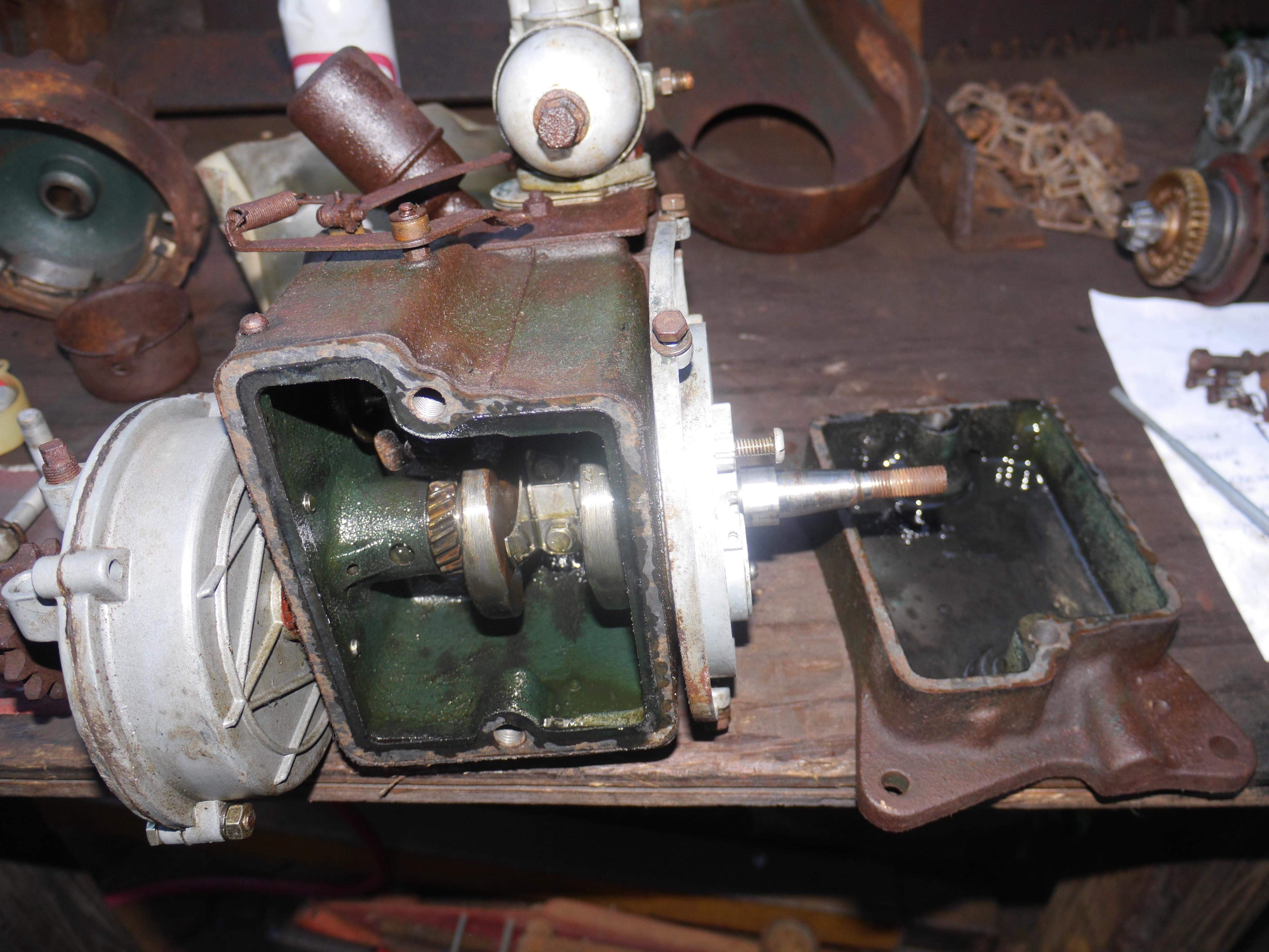
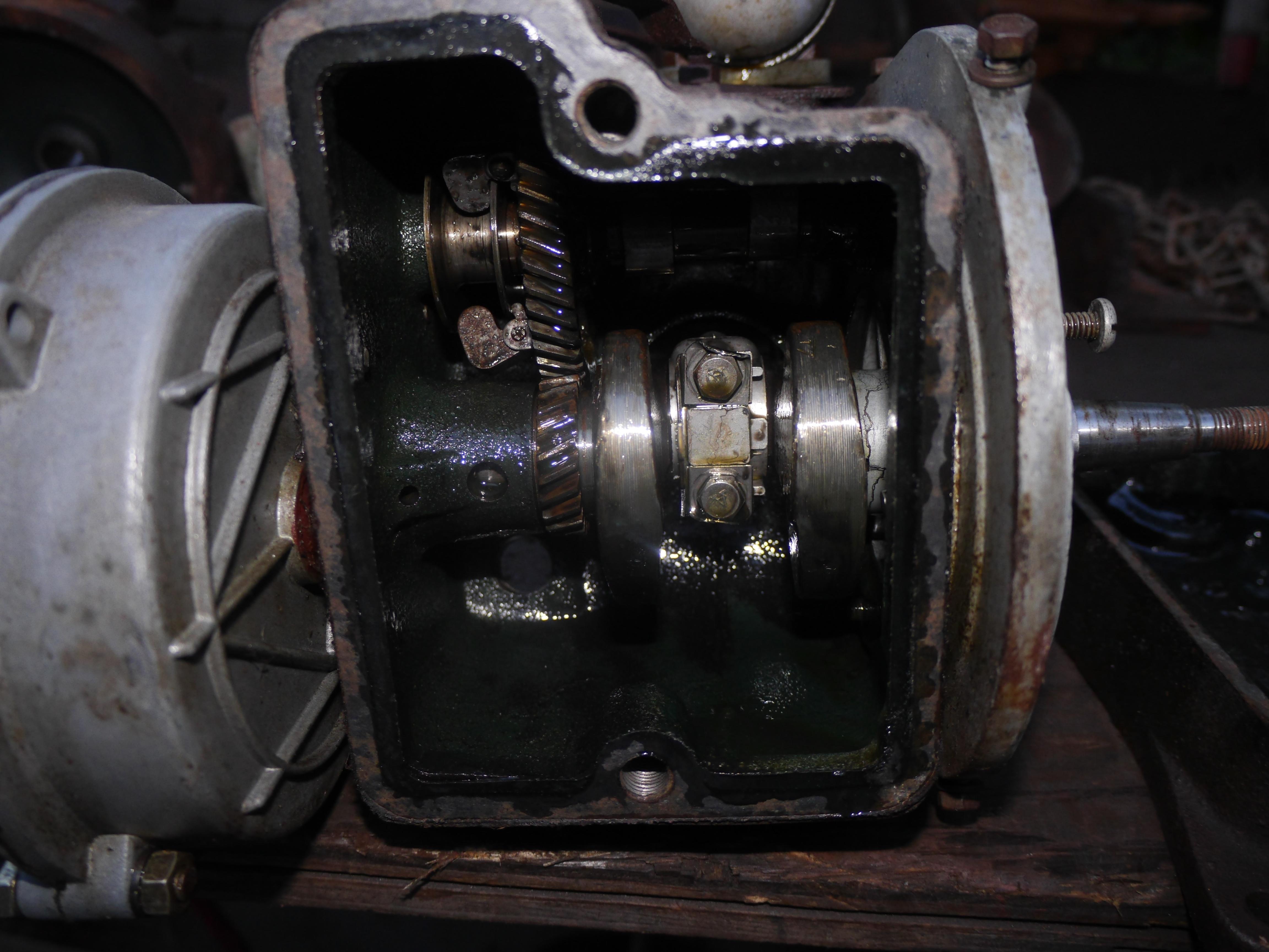
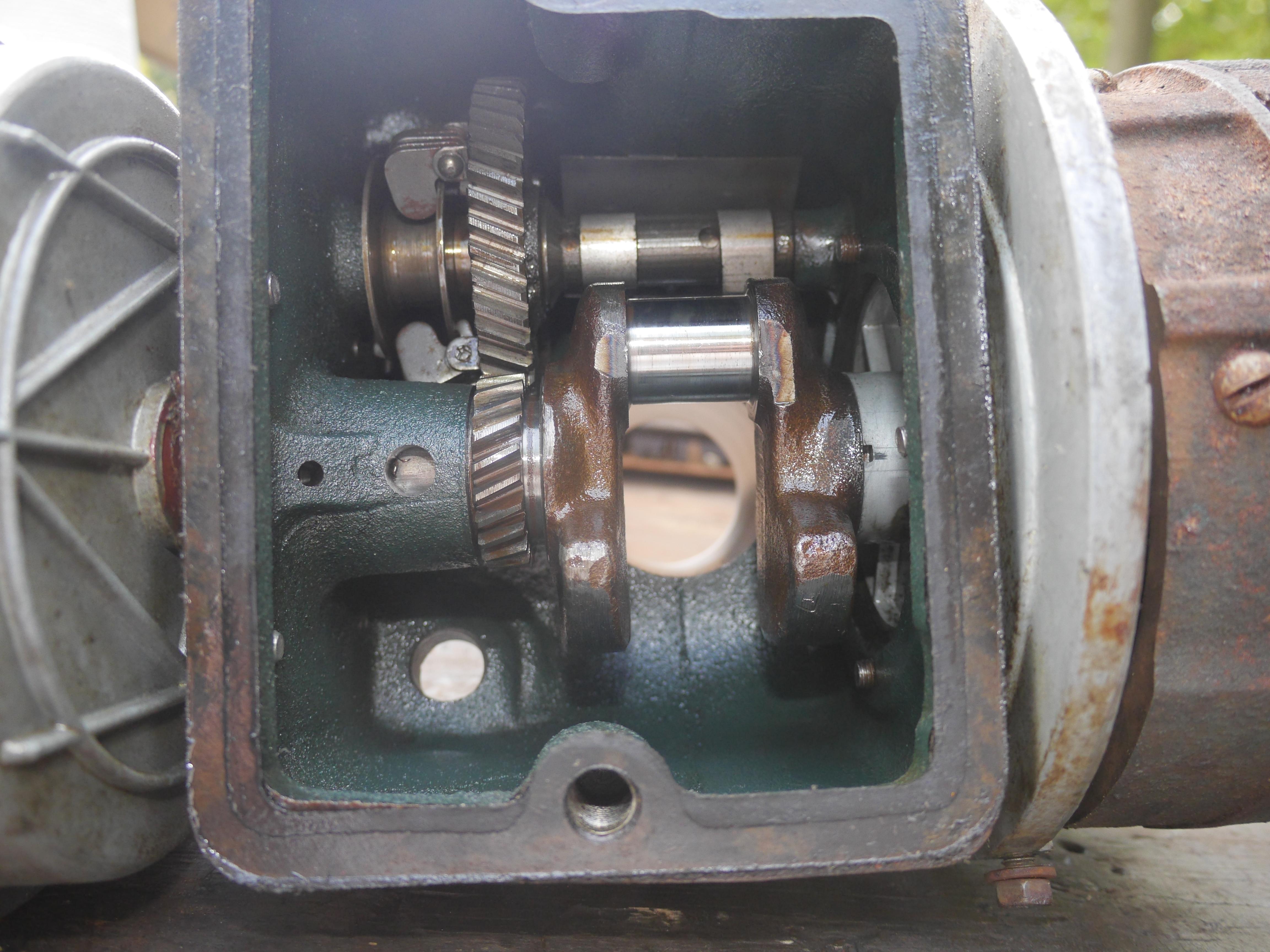
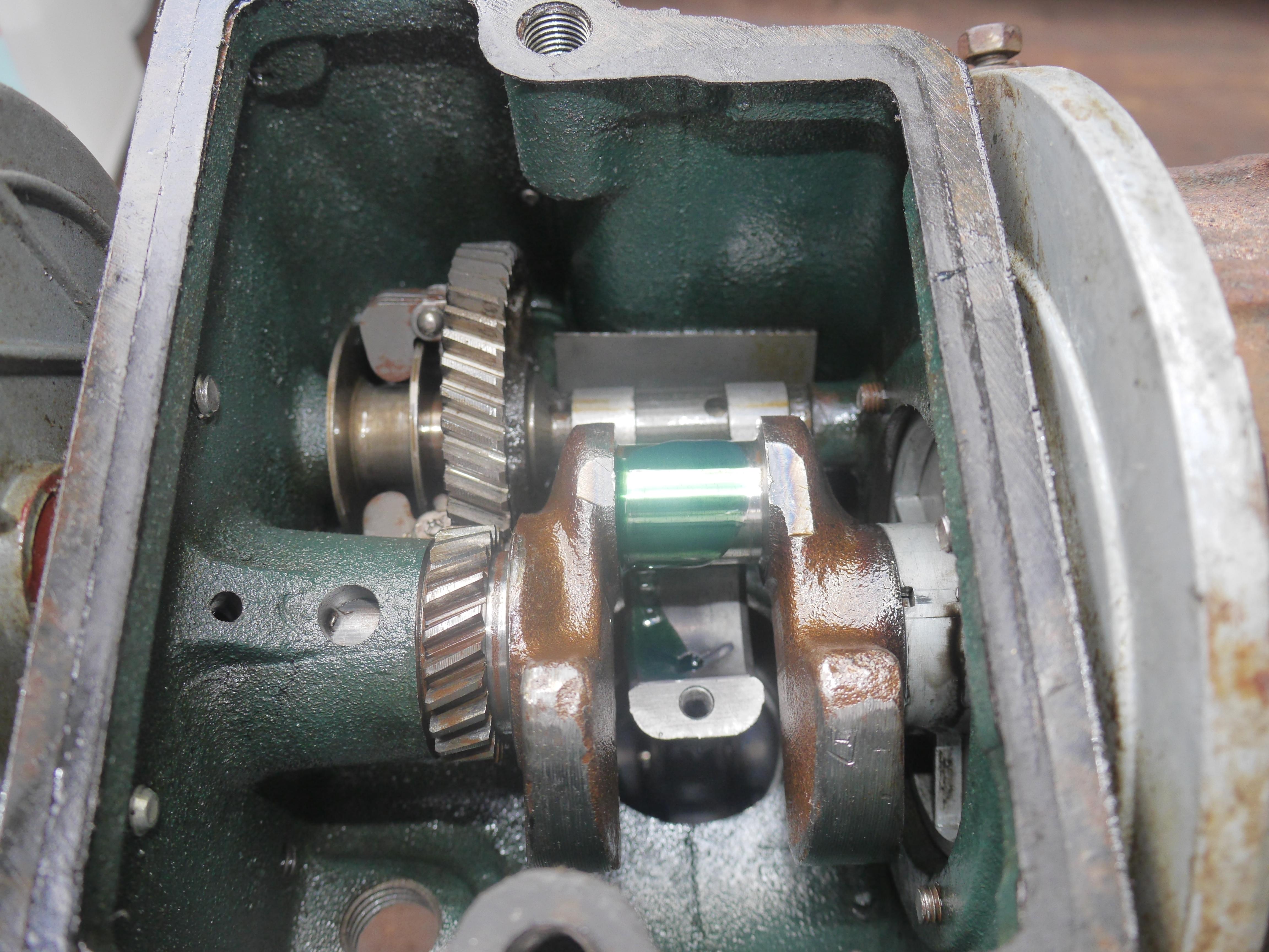
Since I had to order a set of points, I decided to continue pulling the engine apart. I drained the old oil, which was green in color. Either a Brad Penn oil was used, or the oil chemically started to dissolve the green glyptal inside the block. I always pull newly acquired engines apart since there is no harm in flushing out the oil pan and making sure that the piston rings are not seized. This engine looked surprisingly good inside. There was a little surface rust on the crank gears and crankshaft counterweights, but no physical damage was present.
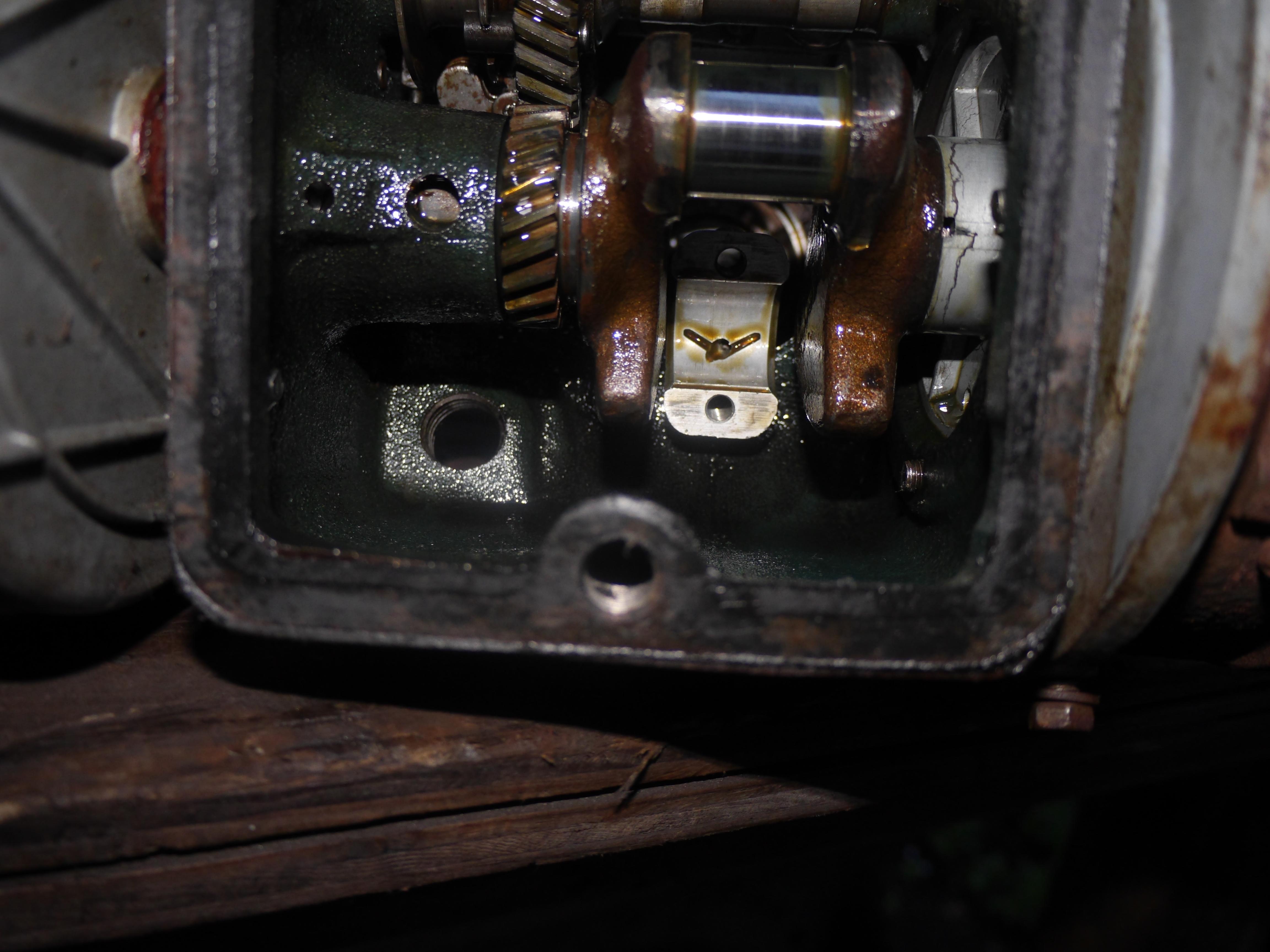
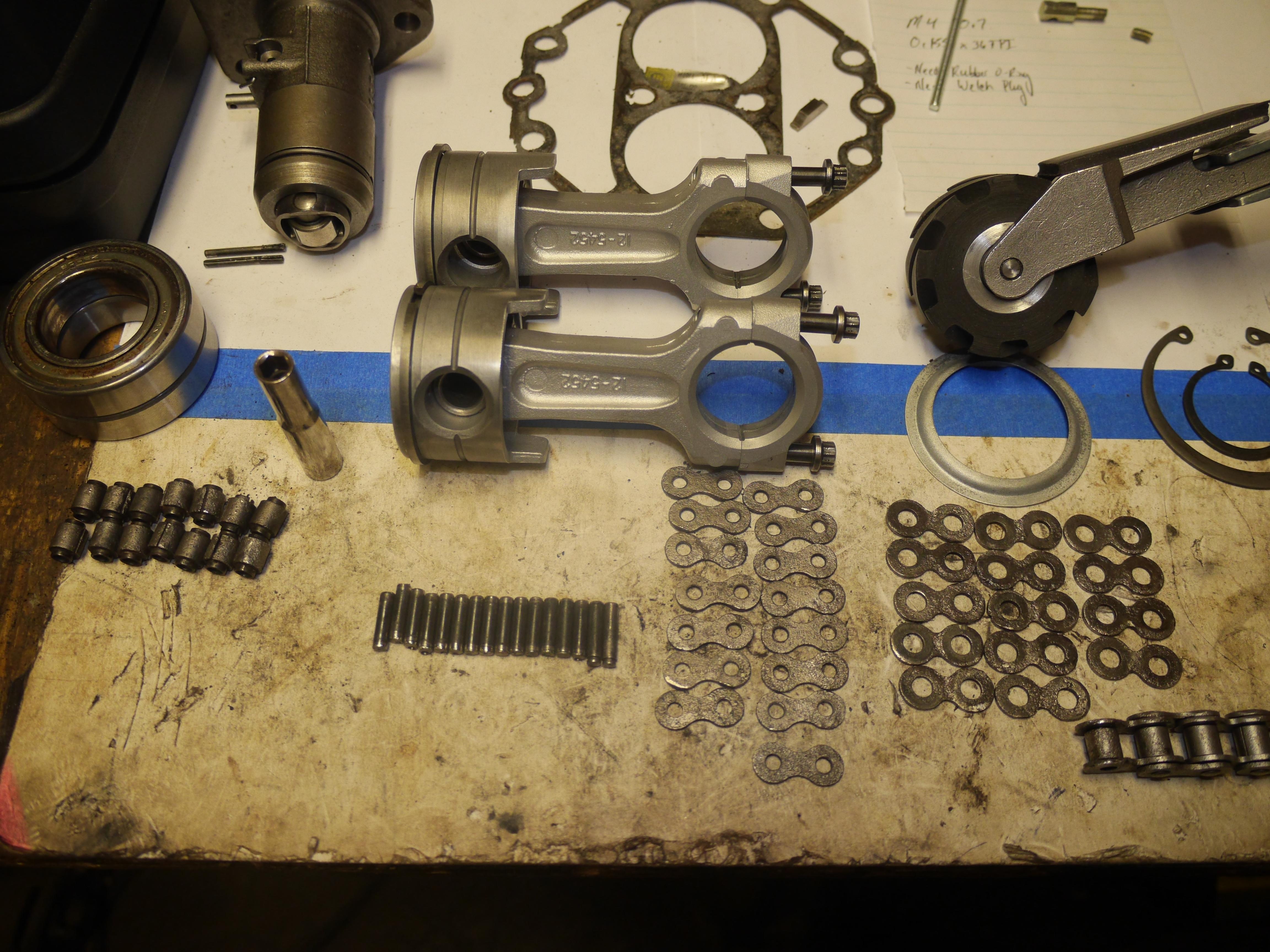
I pulled the connecting rod bearing cap and was thrilled to see that the aluminum rod cap was nice and clean and the crankpin was nice, bright and smooth. Just further proof that this engine had very little run time on it. The piston looked good albeit a little tarnished from dried up oil. To my surprise all of the rings were free in their grooves.

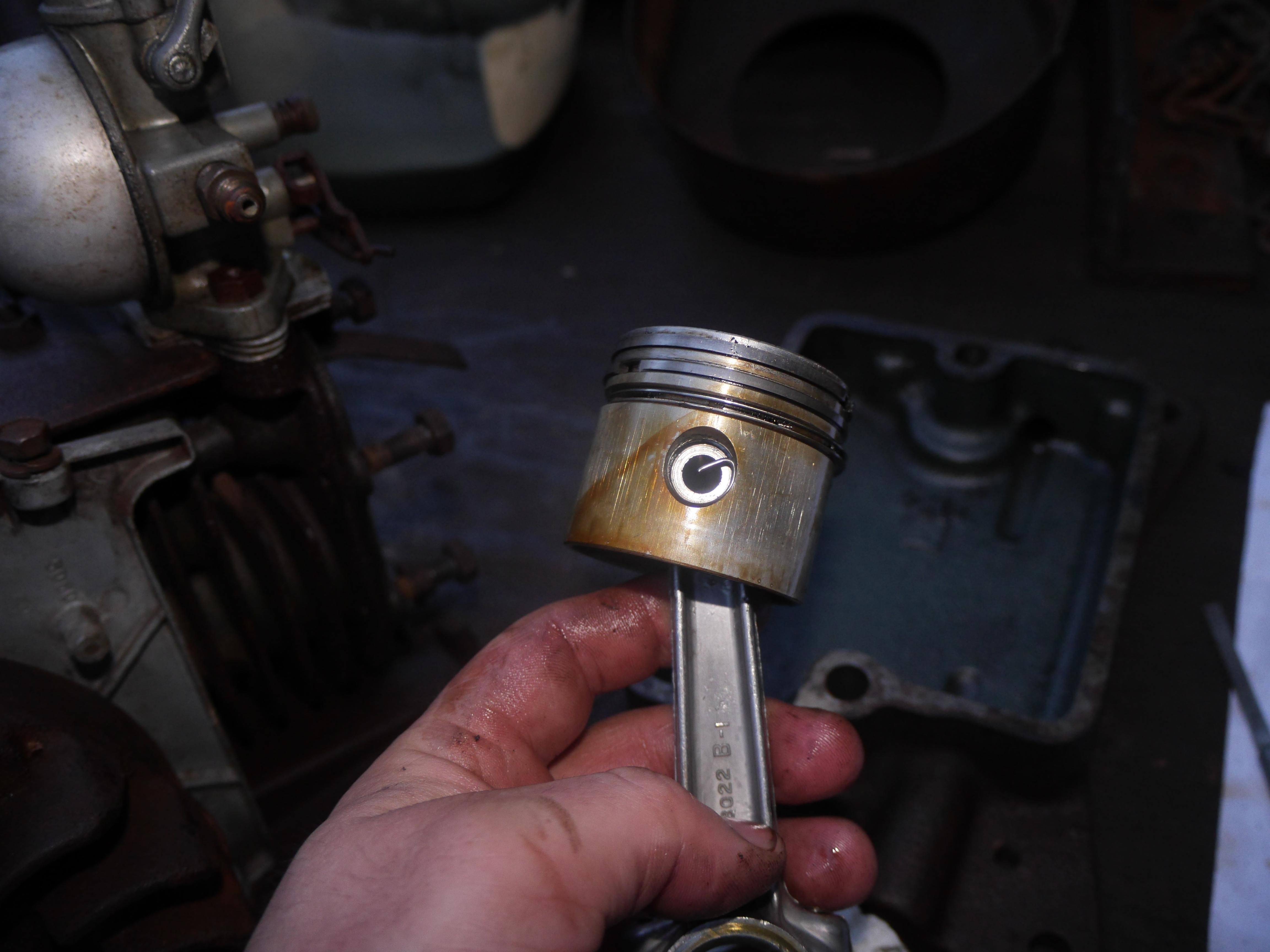
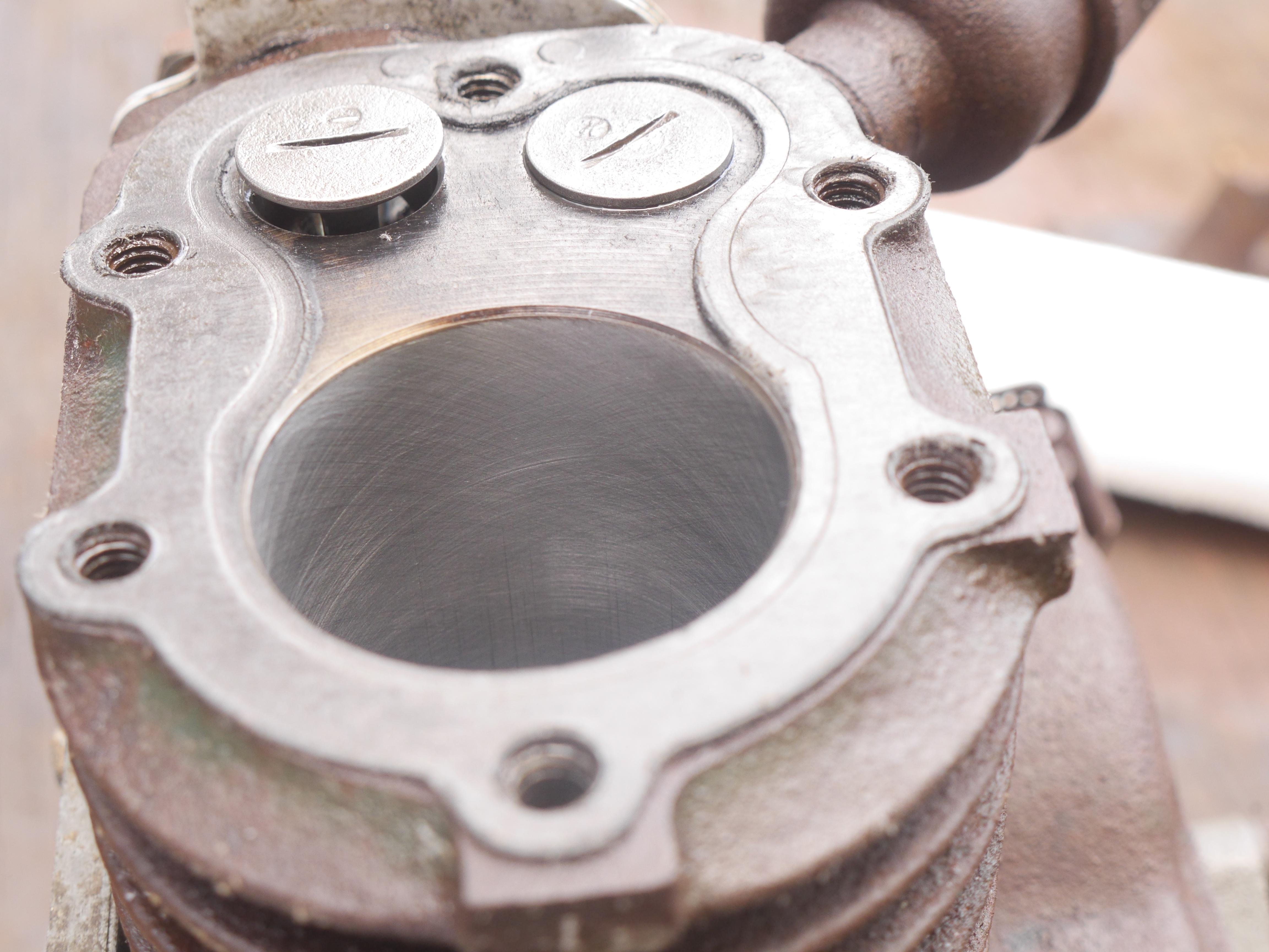
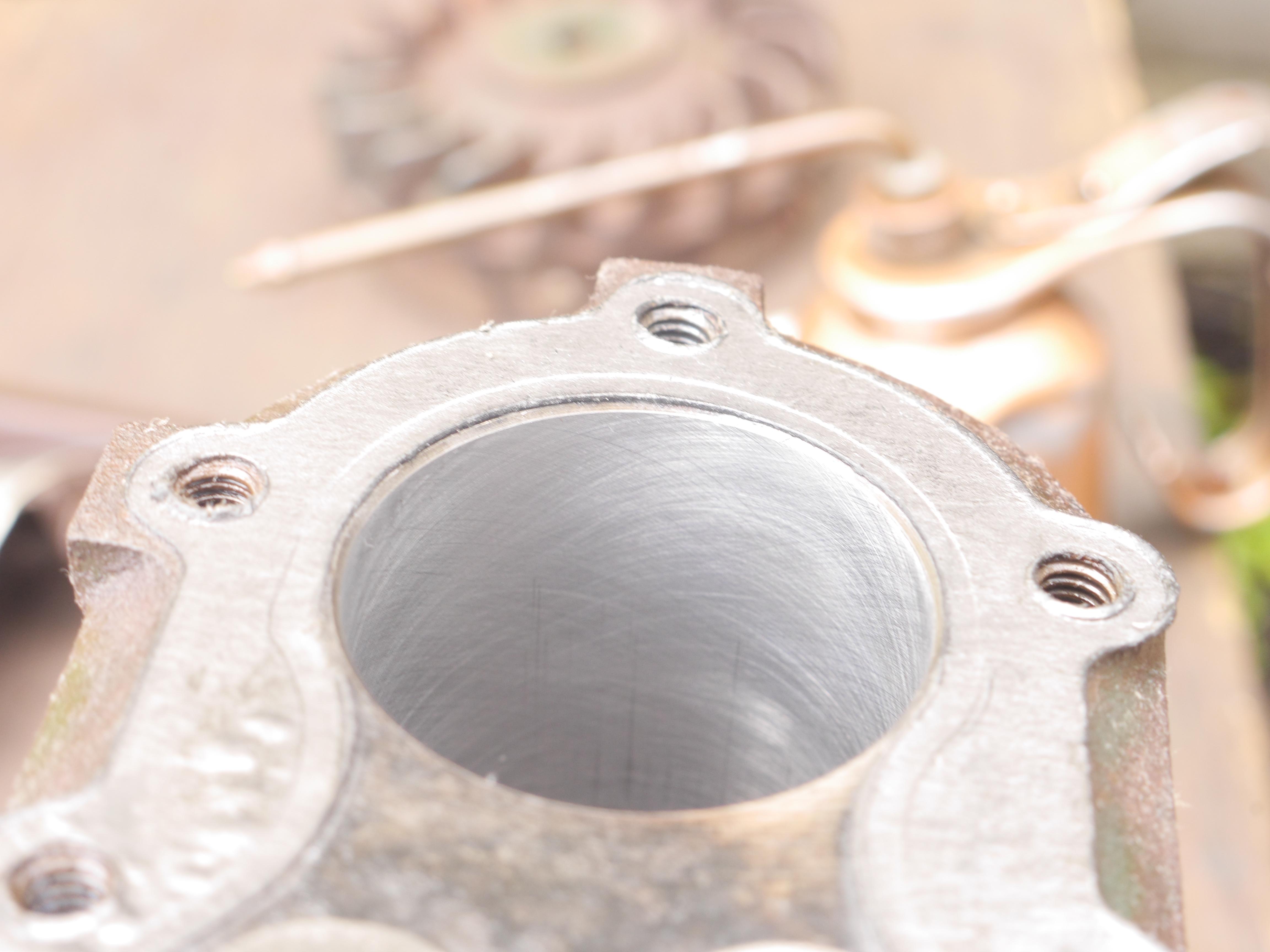
The cylinder looked pretty decent despite the age of this engine. The scoring and pitting in the cylinder from sitting for decades was minimal. All of the irregularities should clean up with minimal honing. At this time the piston came out of the ultrasonic cleaner in pretty much the same condition it left the factory.
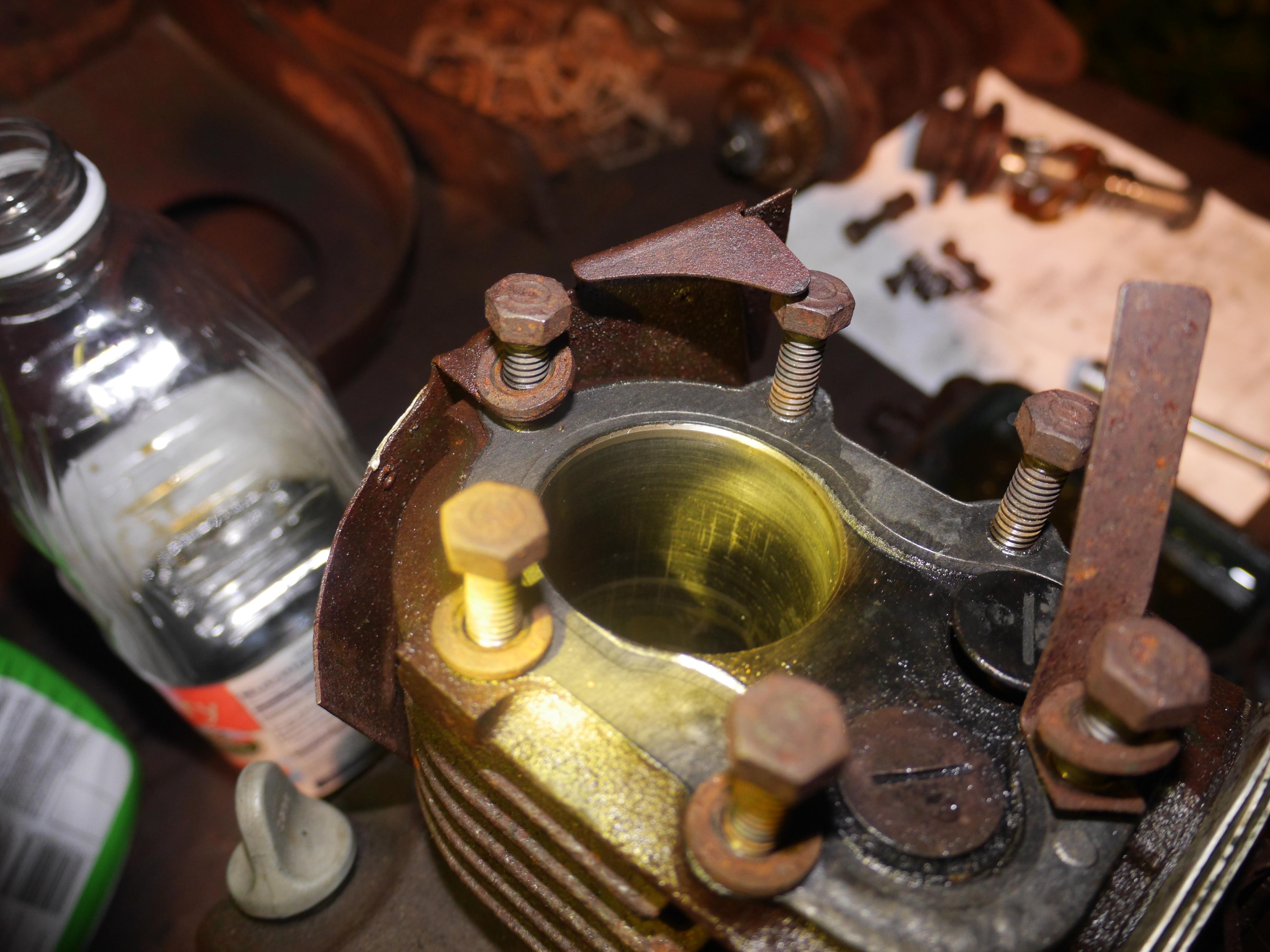


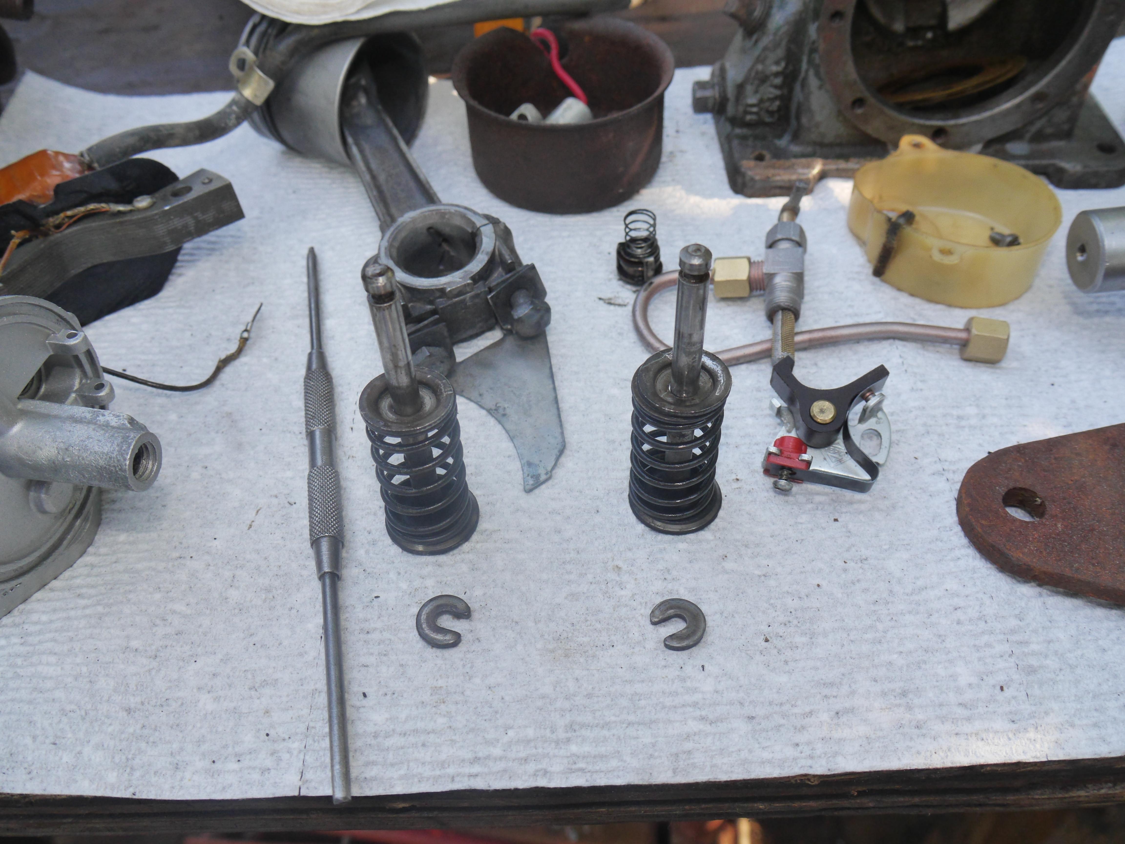
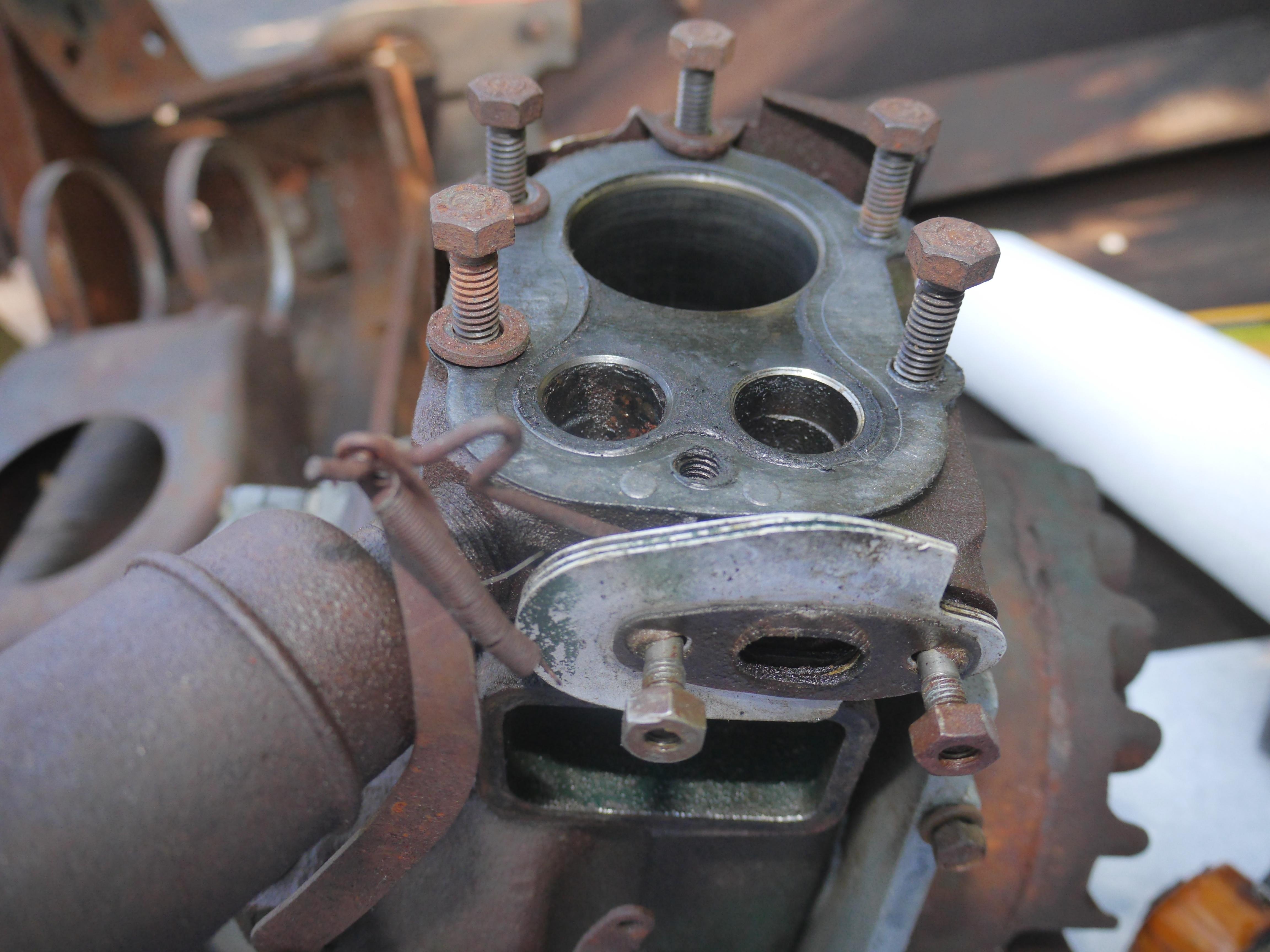
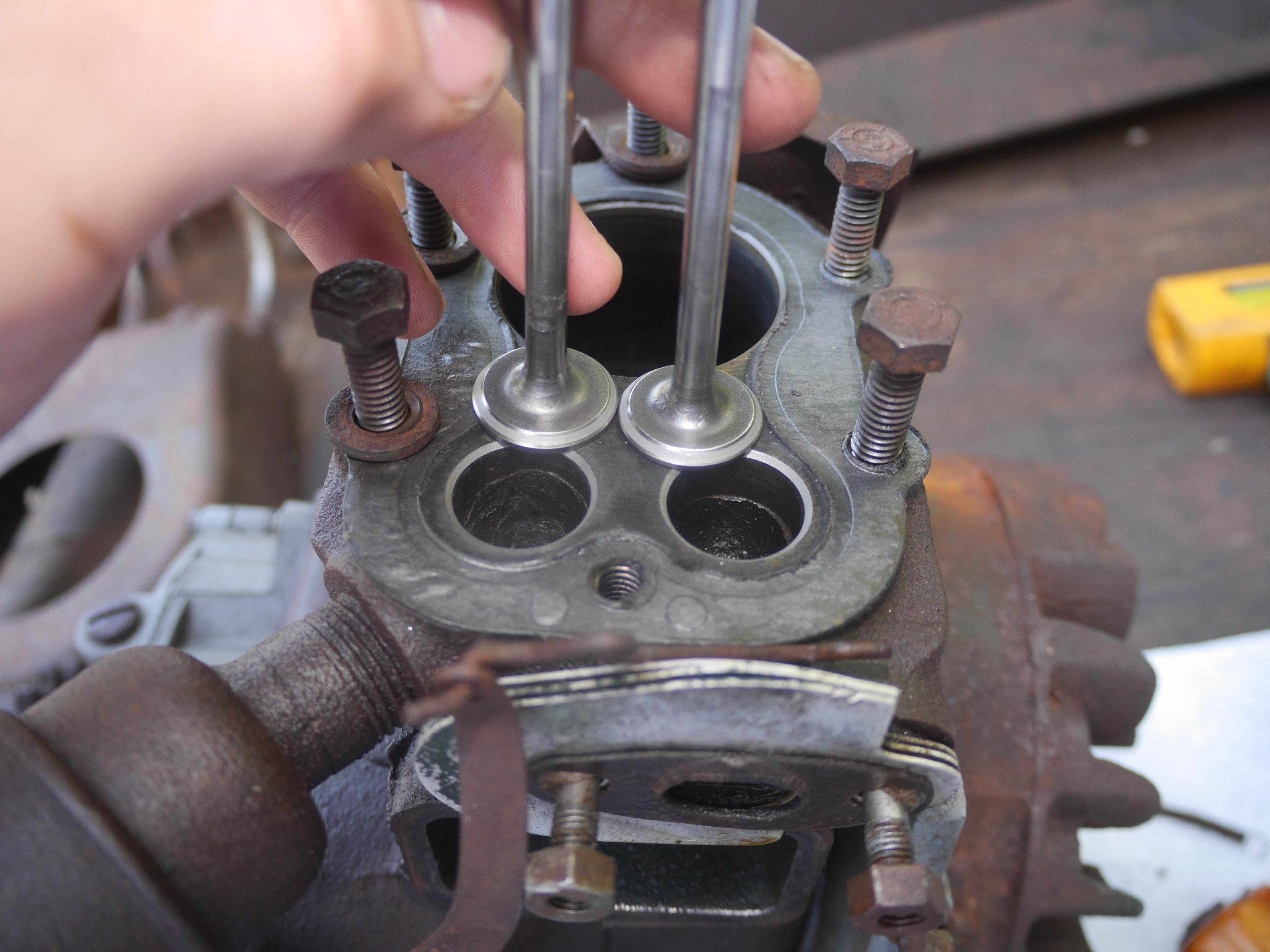
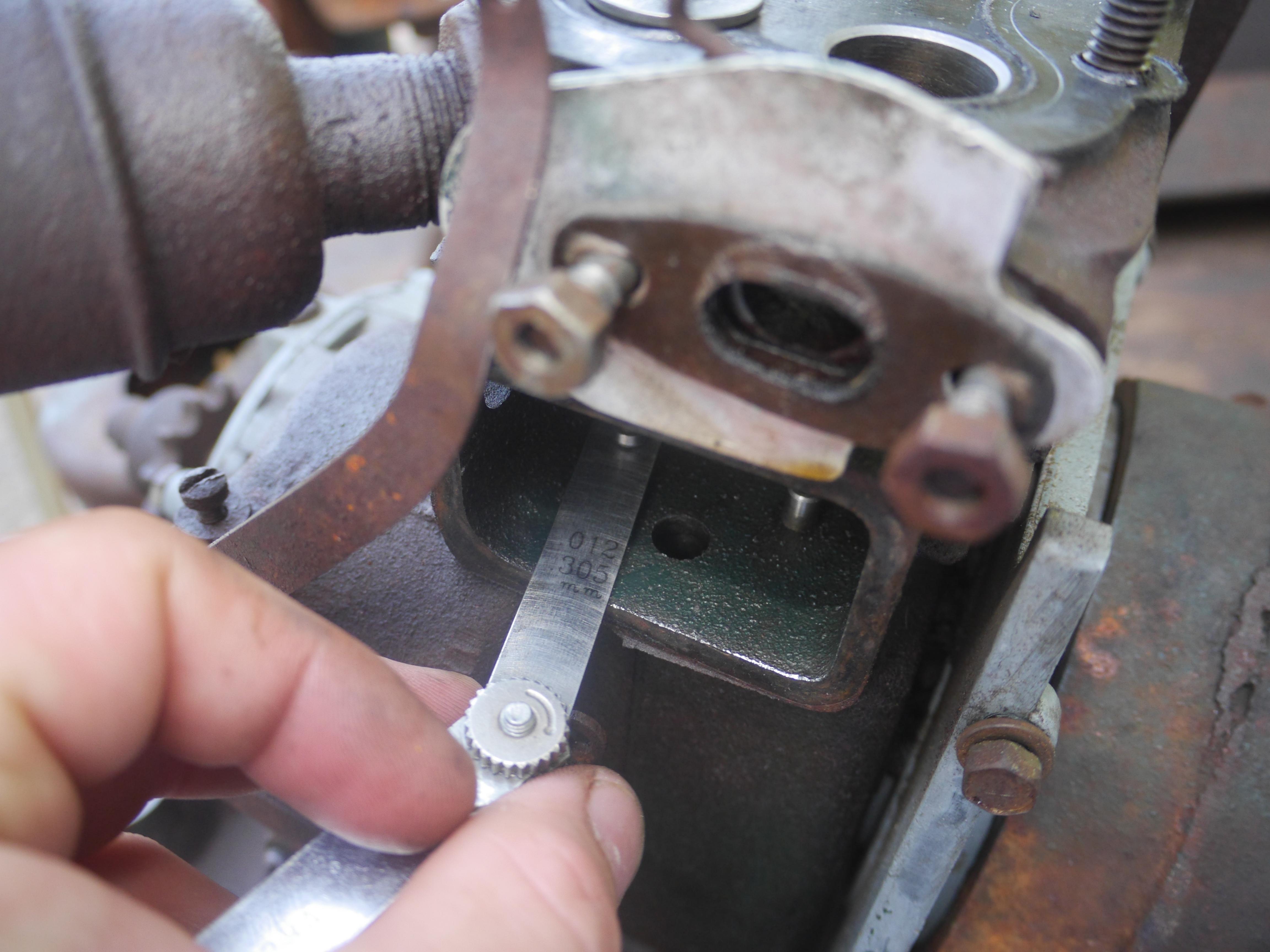
In order to continue, I pulled the intake and exhaust valve from the engine so that the stems could be cleaned, the valve guides could be reamed, and the valves could be cut and lapped. The valves were not incredibly dirty or pitted, but the valve pockets in the cylinder were pretty nasty. After cleaning everything up, I was able to lap the valves back in place with only having to lightly re-cut the valve seats. Since the valve tappets do not have any form of adjustment, it is necessary to grind the stem of the valve down to set the valve clearance. This is done in the same manner as a Briggs & Stratton engine.
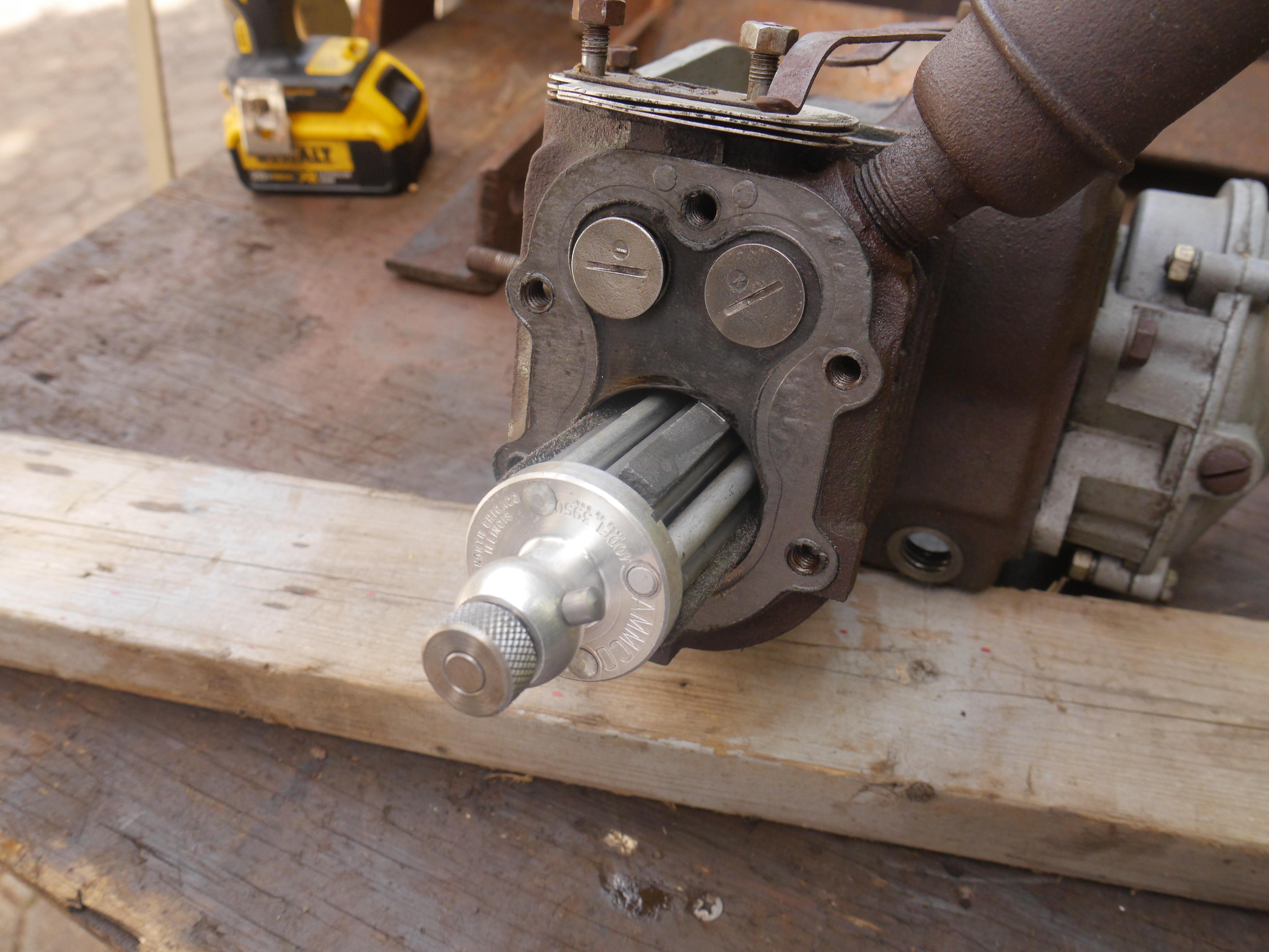
With the valves all cleaned up and reinstalled, the only other mechanical aspect of the engine that had to be addressed was the honing of the cylinder. Since this engine has just a 2.0 inch bore, I could not use my rigid body Sunnen AN-815 hone. Instead I used my Ammco 3950 rigid body "junior" hone. This hone functions the same as my larger Sunnen hone, just not as fancy. In just a few rotations of the hone, the high points of the cylinder were highlighted. In this case a majority of the cylinder cleaned up with next to no honing required. There were very few vertical striations in the cylinder, but nothing major. In just a few minutes the cylinder looked basically perfect.

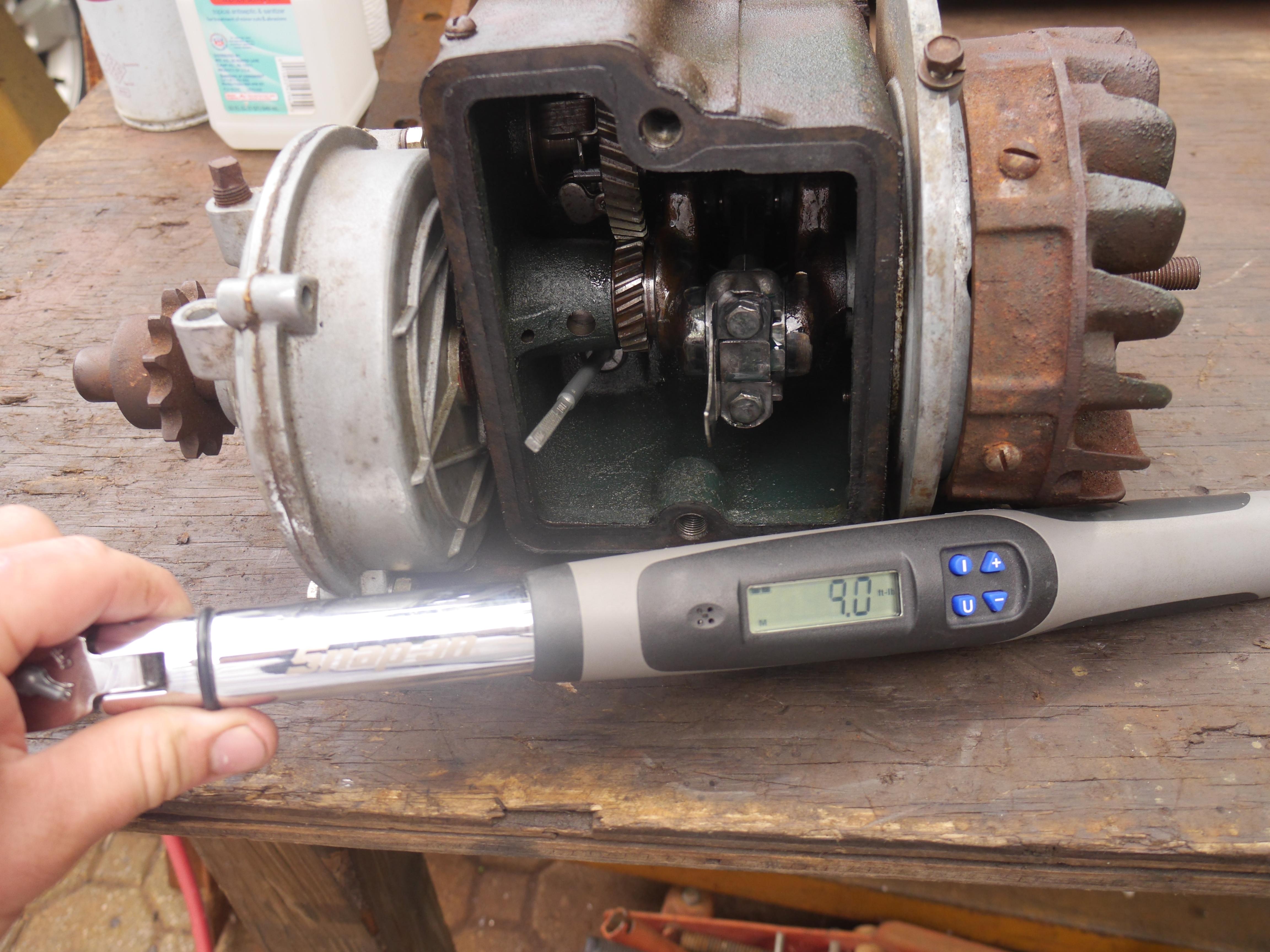
After the honing process is complete, it is imperative to flush out any grit lingering in the crankcase. There was no need to pull the entire engine apart, so it took quite some time to flush the entire inside of the crankcase out with denatured rubbing alcohol. Once everything was blown out and risned clean, I began re-assembling the engine. I liberally coated the piston and rings with assembly lube, then used a ring compressor to slide the piston back into the cylinder. I ended up re-using the original piston rings as there was nothing wrong with them. When the piston was completely inserted into the cylinder, I coated the crankpin and the aluminum connecting rod bearing with assembly lube, and then proceeded to torquing the connecting rod bearing cap bolts. This is not a particular big engine, so just 9.0 ft/lb of torque was required. Once the two bolts were torqued down, I re-bent the locking tabs over the bolt faces so that they cannot loosen up and back out.

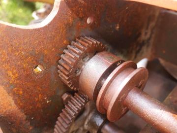
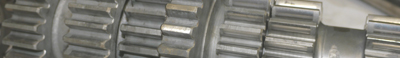
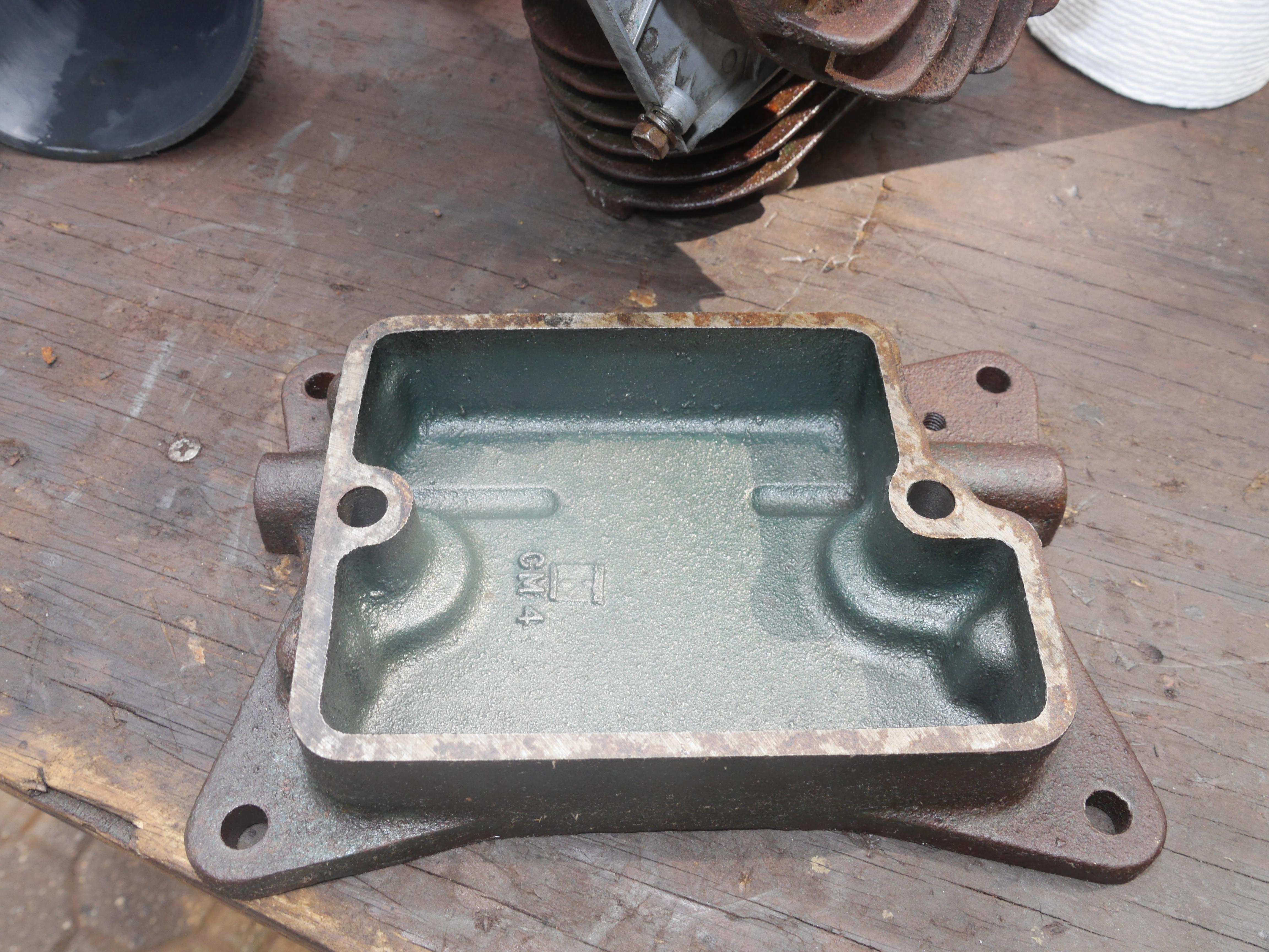
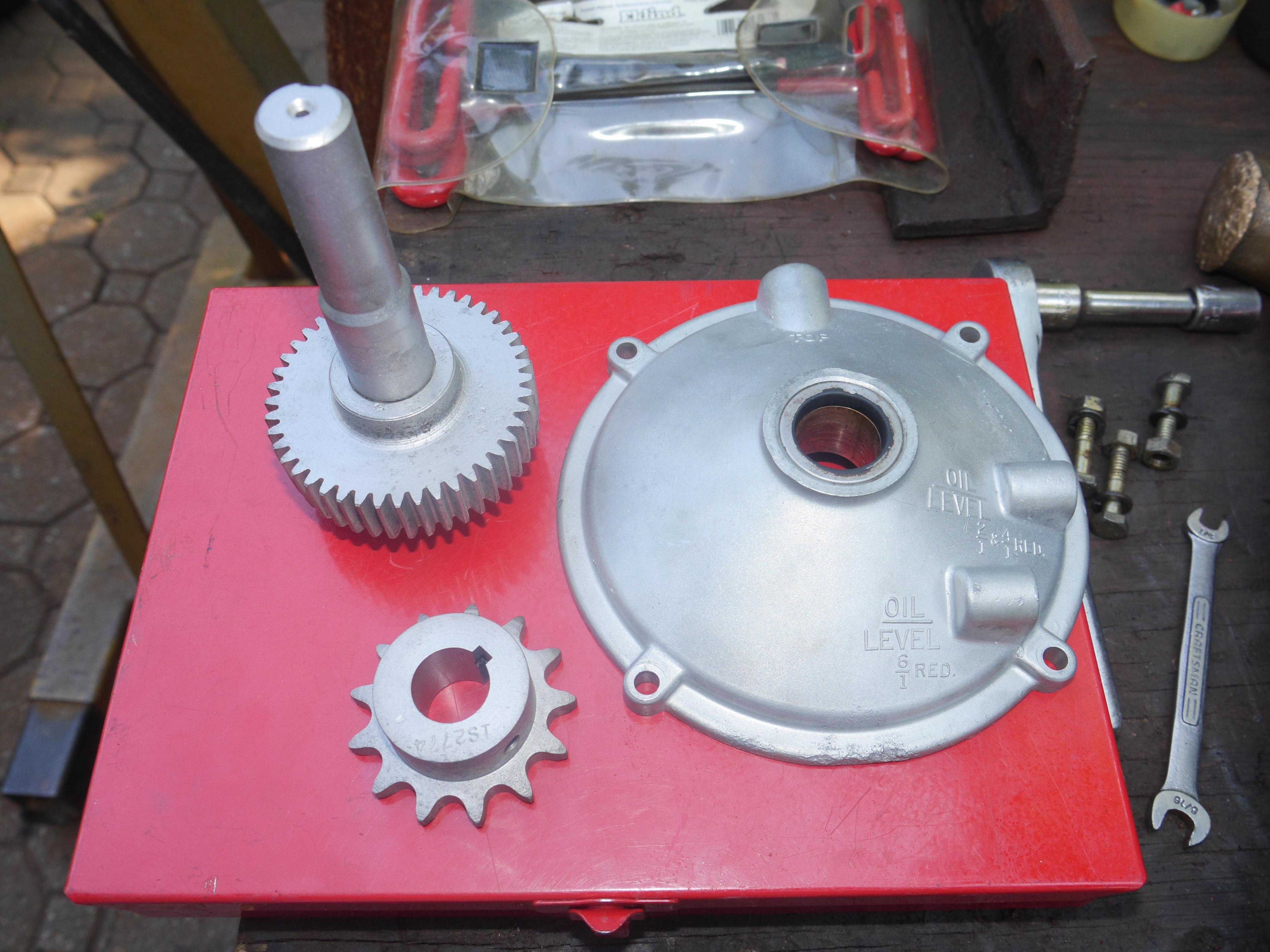
Now that the rotating assembly is complete, I determined that now was a good time to reinstall the oil pan. The oil pan is cast iron and secured by just two bolts. I noticed the rotating assembly felt a little tight when turning the engine over by hand, and decided to pull the gear reduction cover off of the engine. I am glad that I did, the gear reduction gears were quite rusty. I ended up pulling the reduction shaft out of the aluminum housing and bead blasting the components. This gave me the chance to also blast the drive sprocket on the output shaft of the reduction. Note that this is a 4:1 reduction. The driven gear show a little bit of wear on the teeth, but nothing major. It was likely run without oil in it.

KiCad Specifics
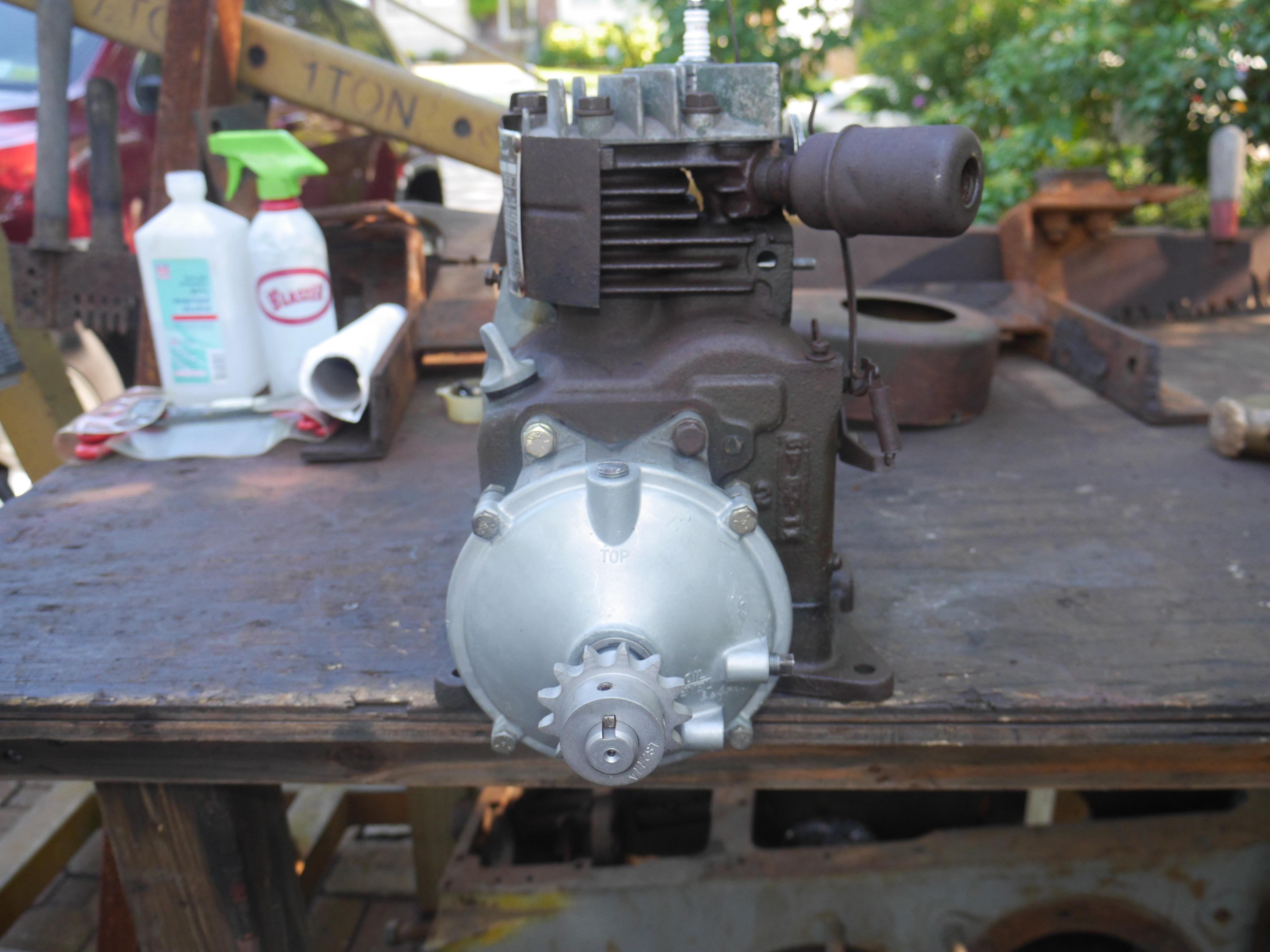
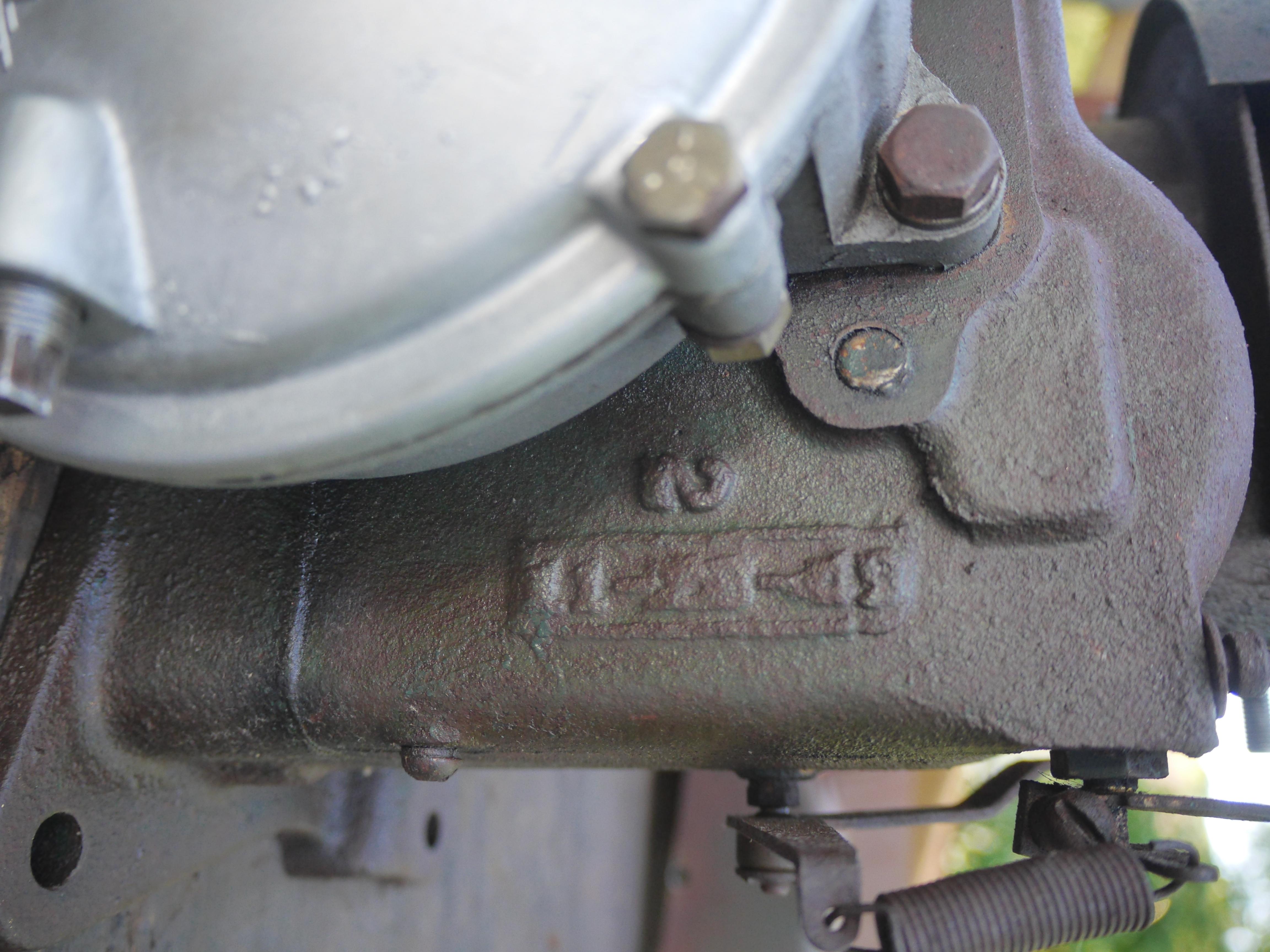
The freshly media blasted reduction shaft looks nice and turns nice and smooth against the crankshaft. I finished re-assembling the reduction when I noticed a set of numbers cast into the crankcase. This was the date code for the engine: 11-23-49

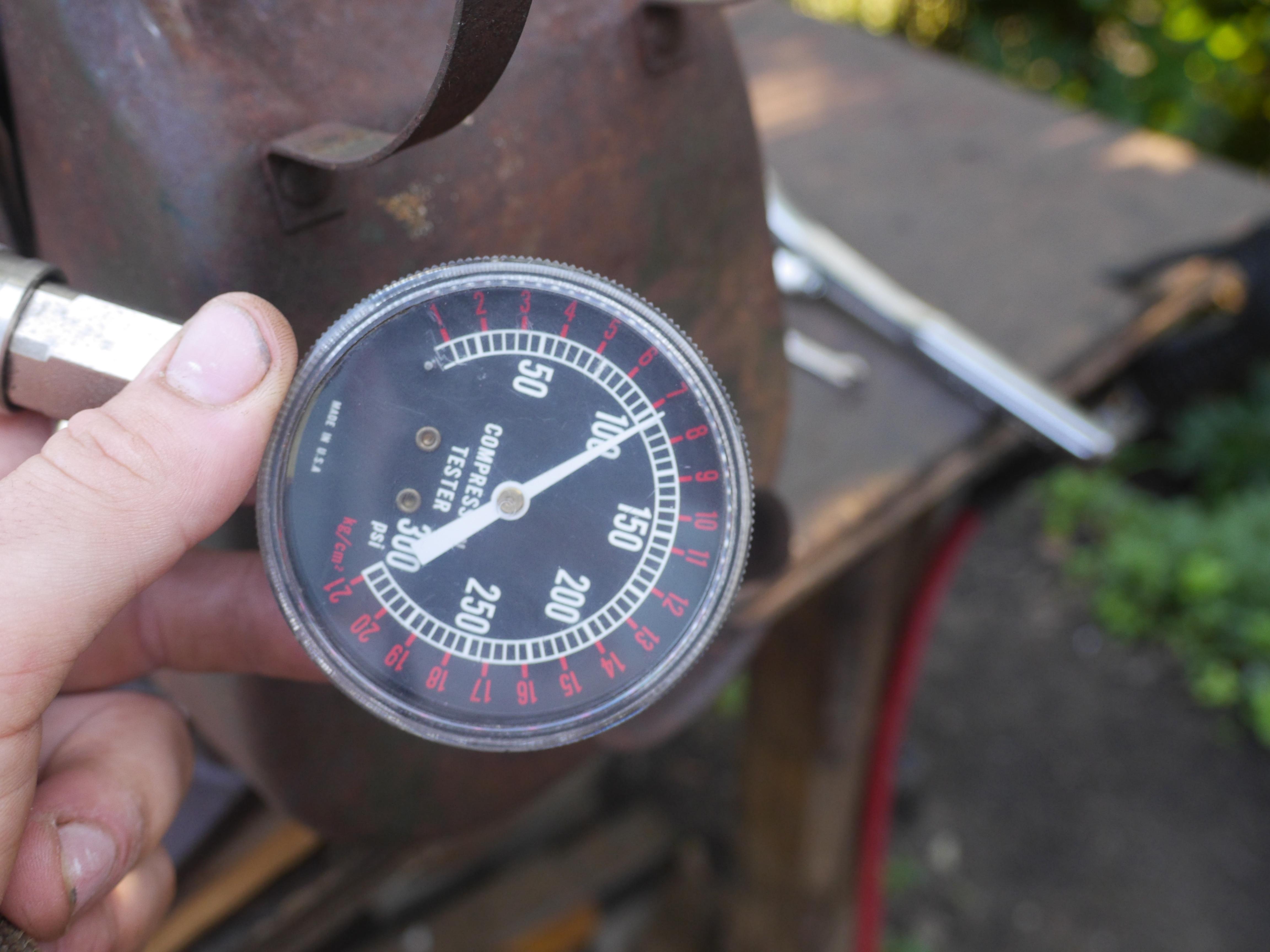
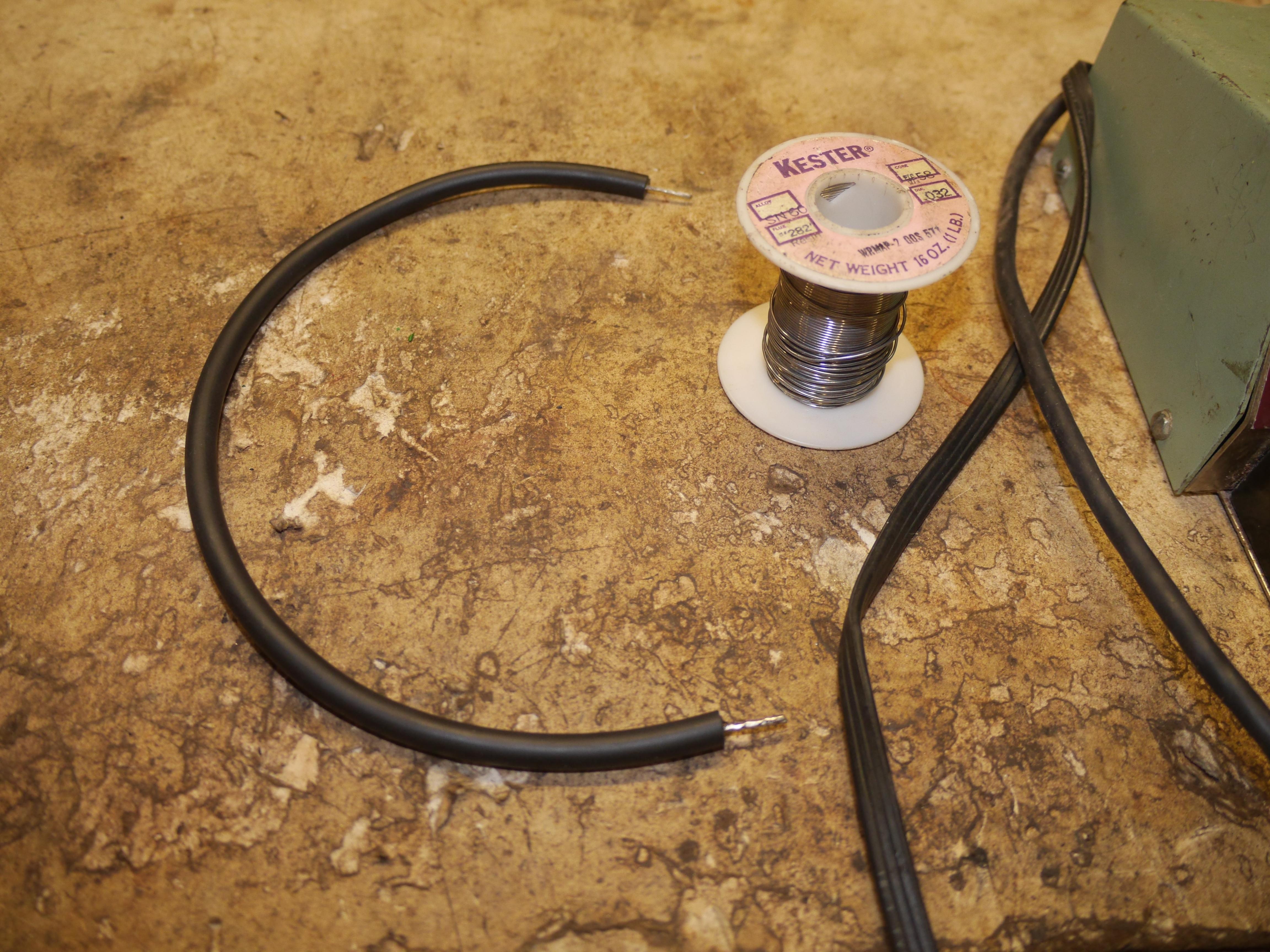
Now that the engine was for the most part assembled, I attempted to repair the ignition coil, and condenser wires with some heat shrink so that I could test the ignition. Despite the points having lost part of their tungsten plating, I had a weak spark at the sparkplug. I pulled the engine over a few times, and then tested for compression. 105psi of compression, not too shabby for a low compression flat head engine. I sprayed a little fuel into the intake manifold and it took right off.
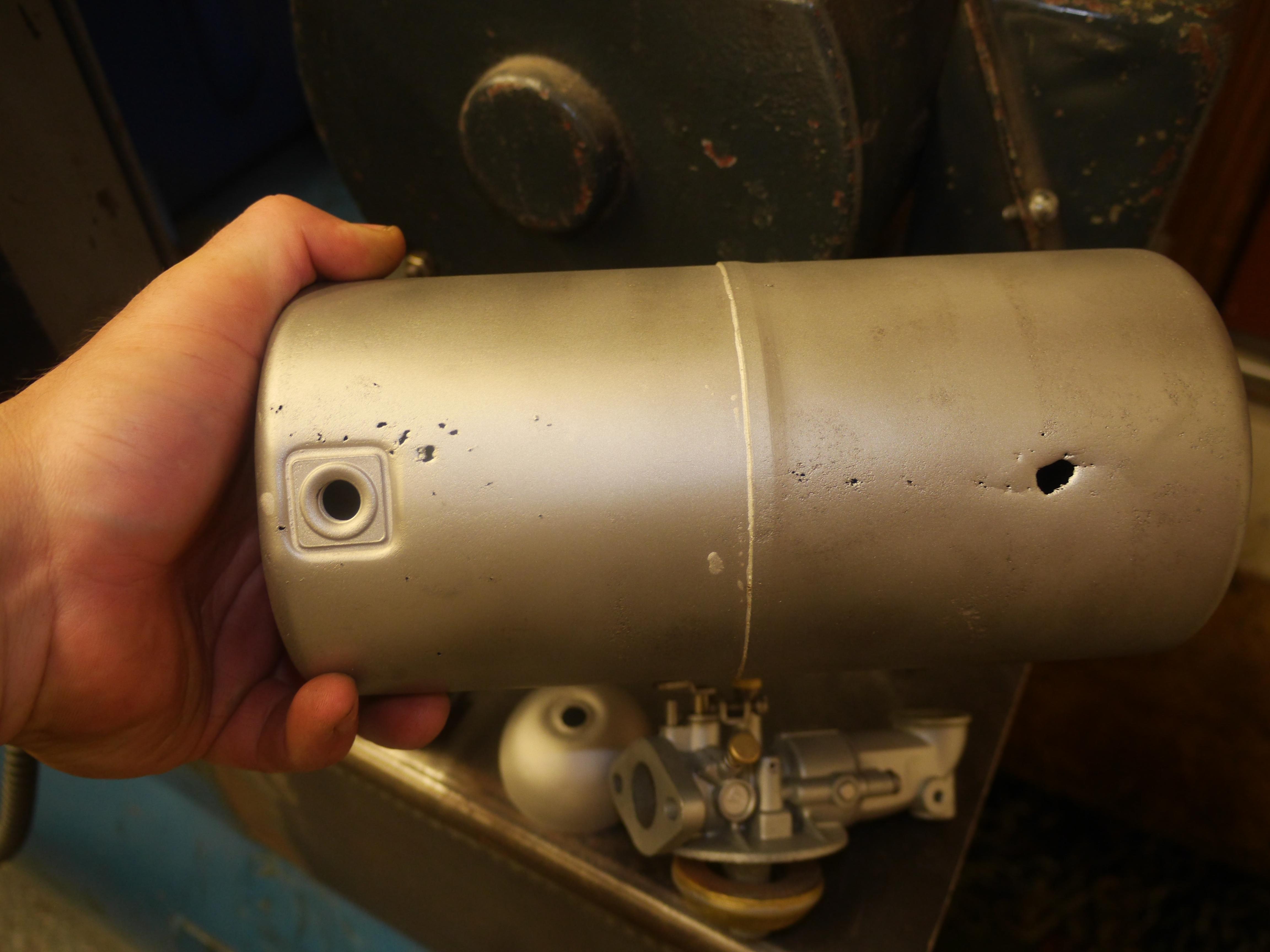
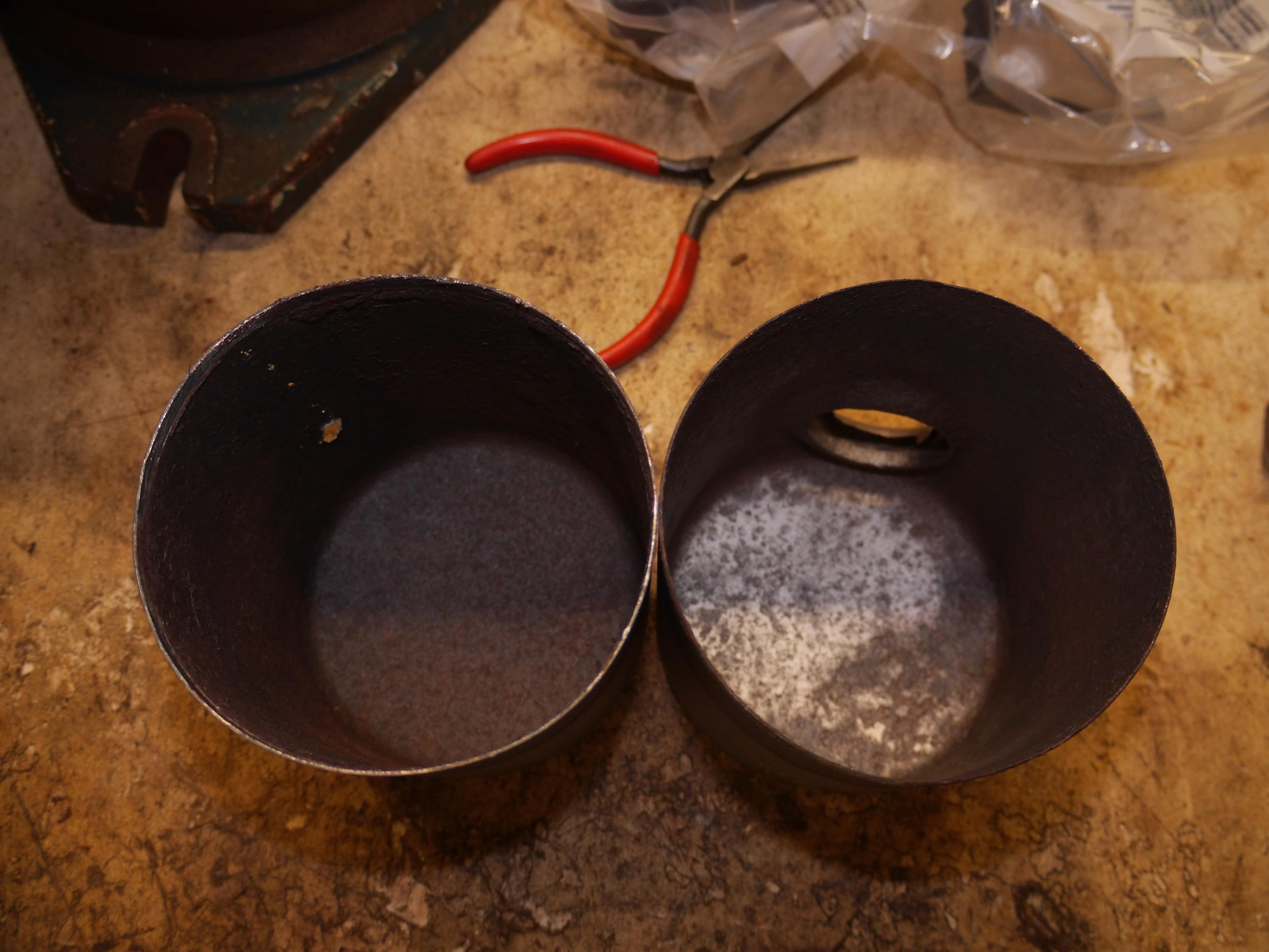
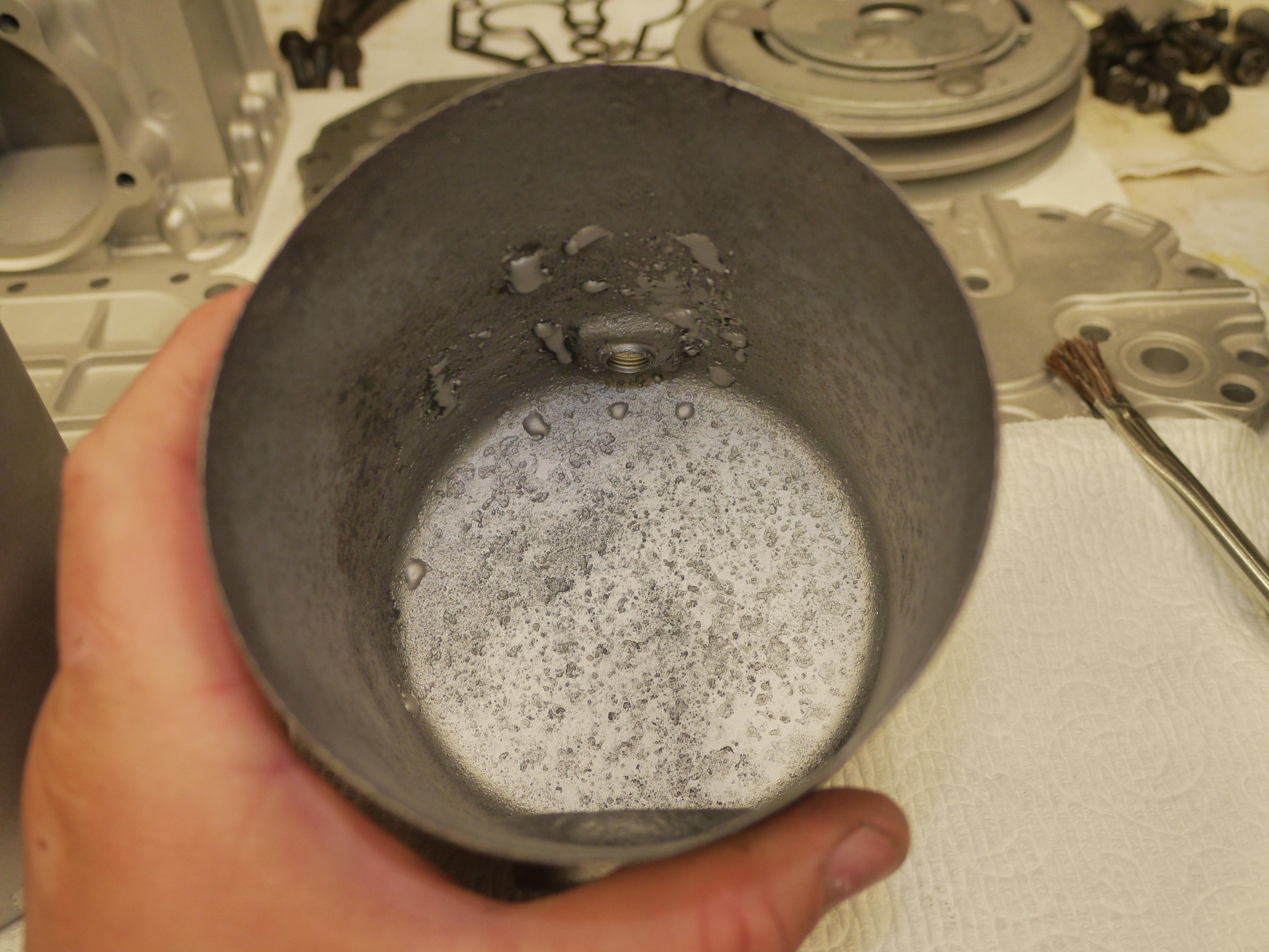
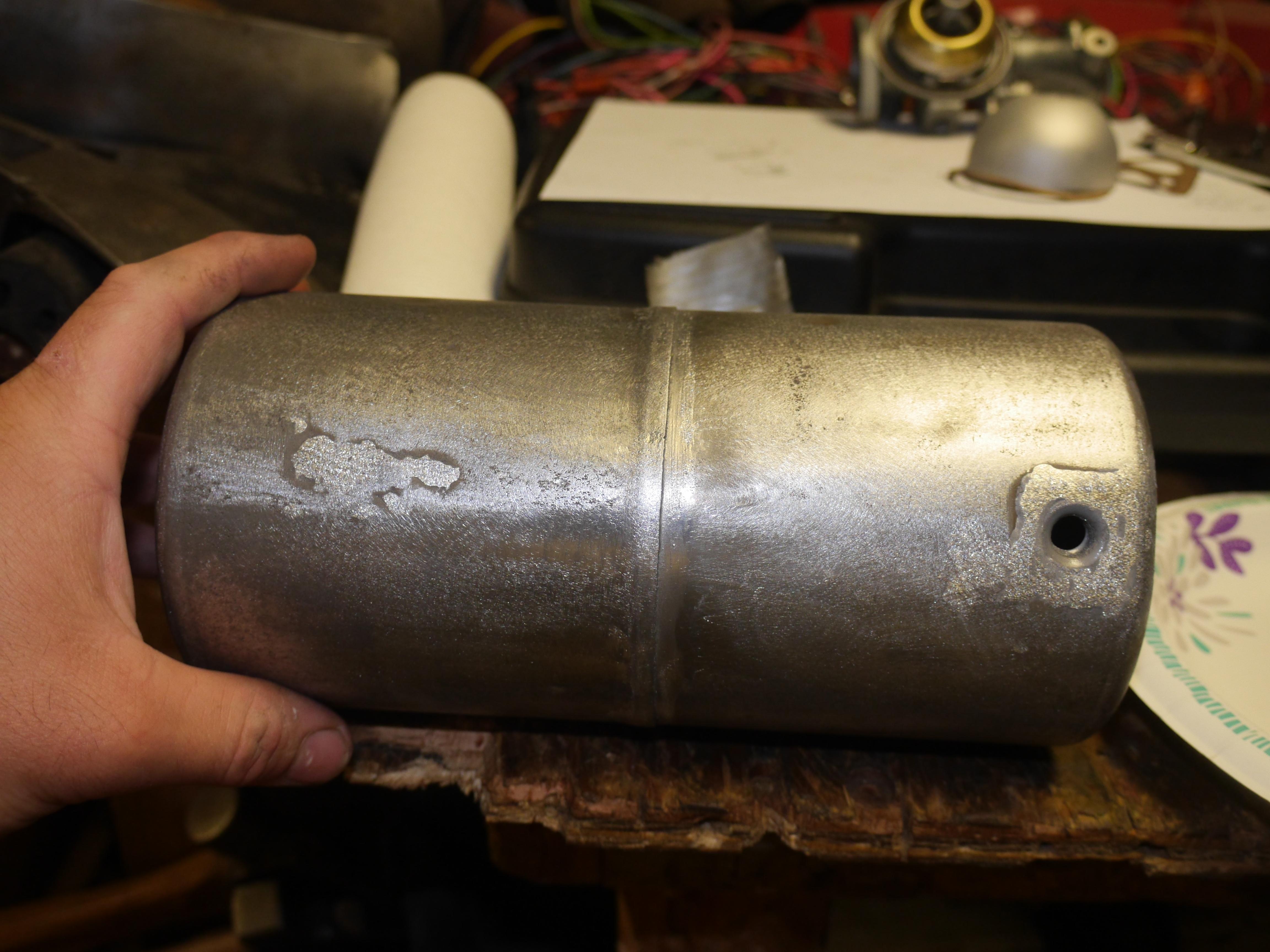
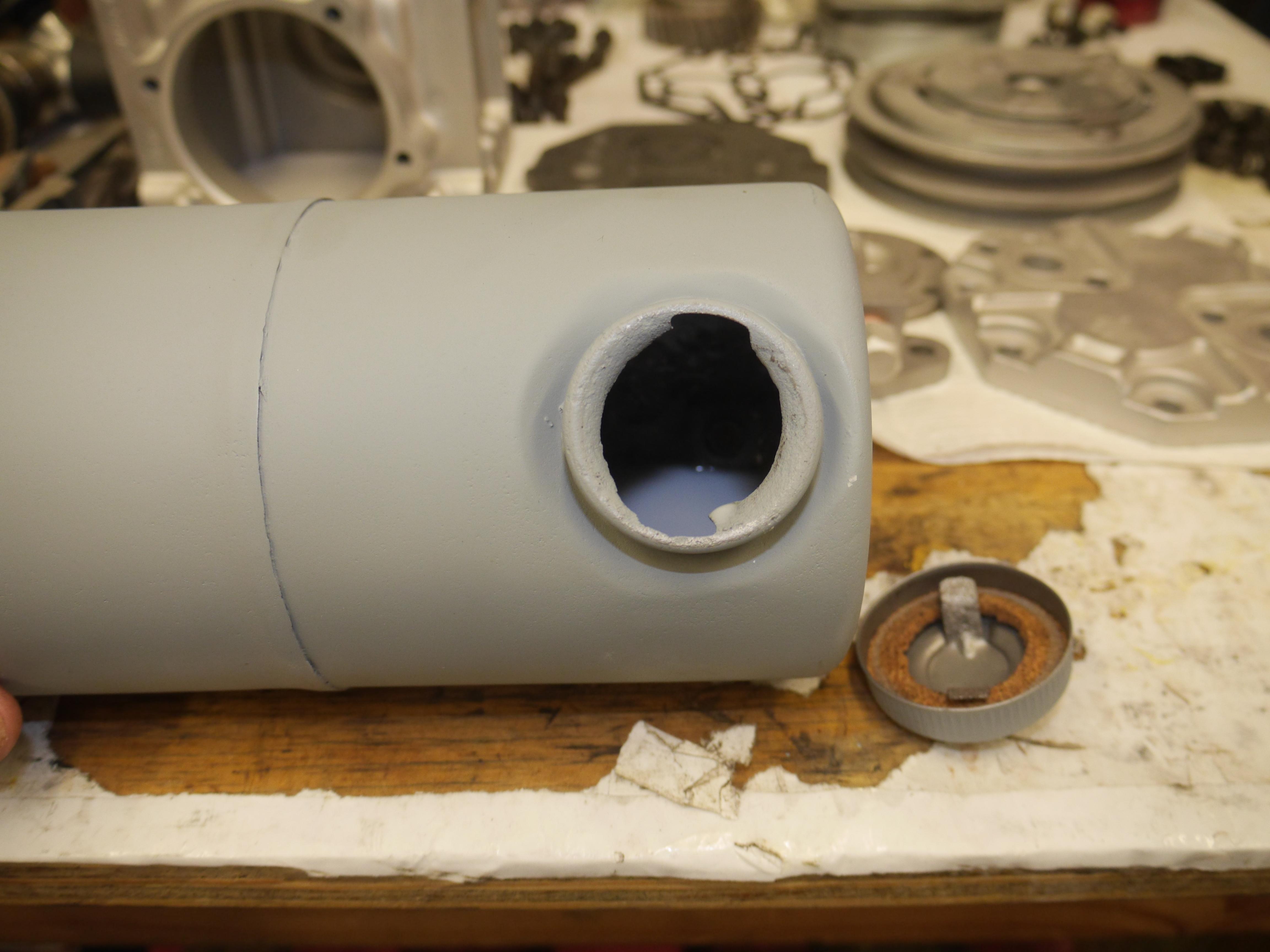
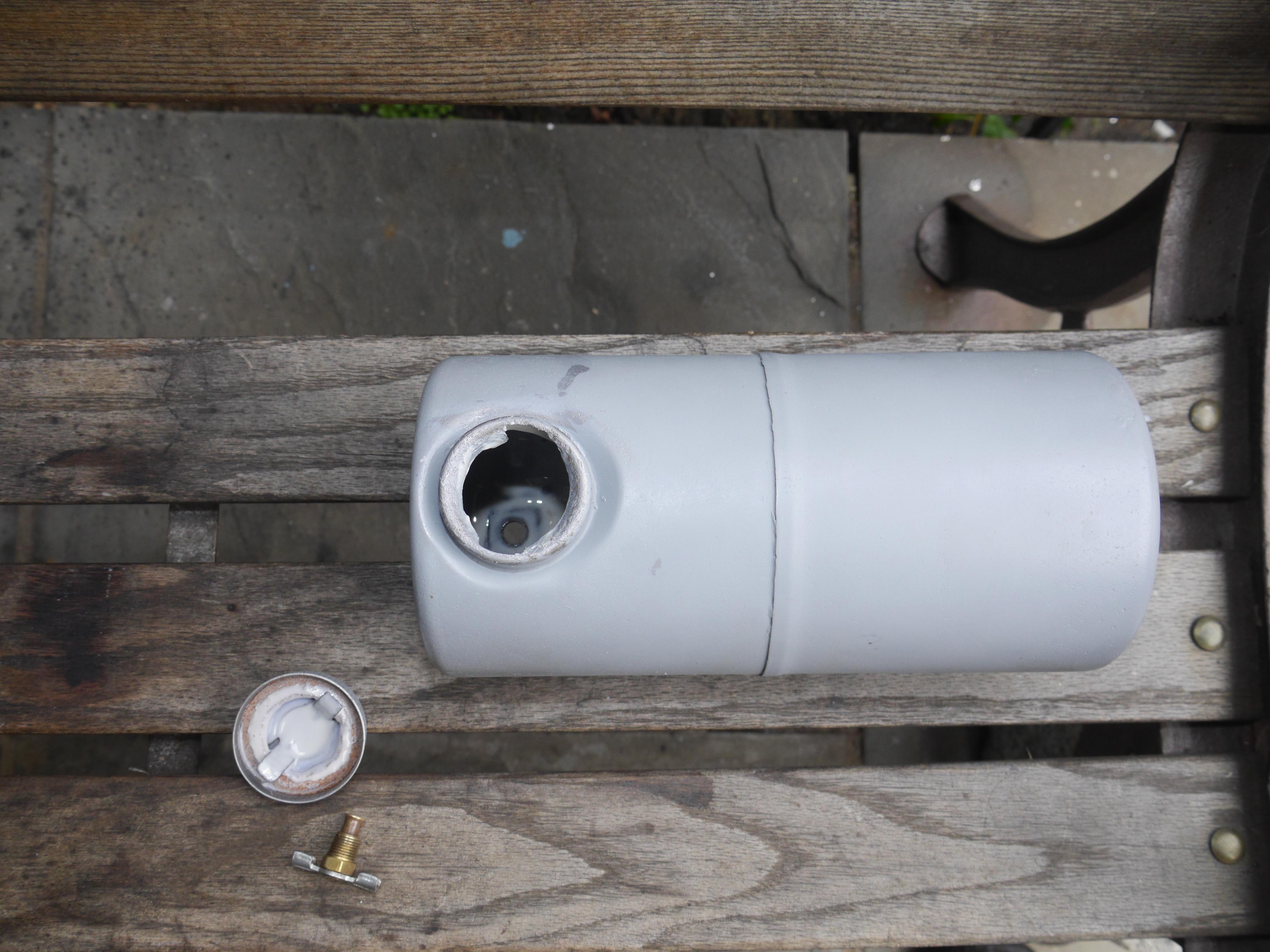
Now that I know that the engine will run, I began cleaning up the original fuel tank and carburetor. Both were very rusty and corroded. The fuel tank looked good until the media blasting revealed all of the holes in the bottom of the tank. I looked online for another fuel tank, but simply none were available. I decided that I would attempt to fix mine before I try spending good money on another used tank that could very well be just as bad. I heated the tank up with my propane torch in order to separate the two pieces. These tanks are simply soldered together with leaded plumbers solder. I circled all of the holes with a marker and began soldering them up. Since the metal was so nasty and corroded, I ended up having to bead blast the inside of the tank, and use an exceptional amount of flux. Finally I was able to get enough solder to stick that I could start repairing the tank. I used my 1950s Hexacon 120 watt soldering iron to heat up the tank and solder. Soldering with a torch is much too risky, since the heat cannot be easily controlled.
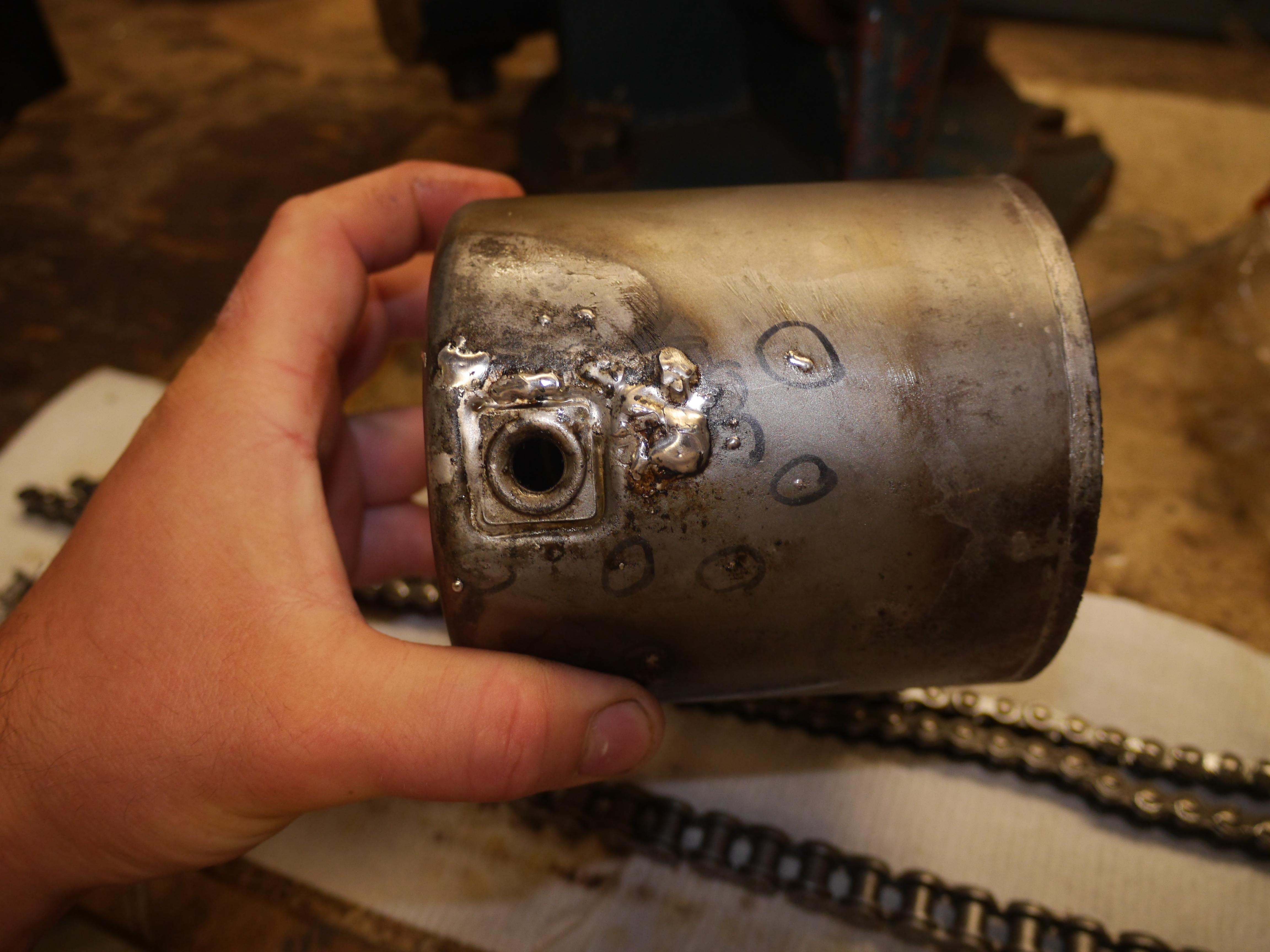
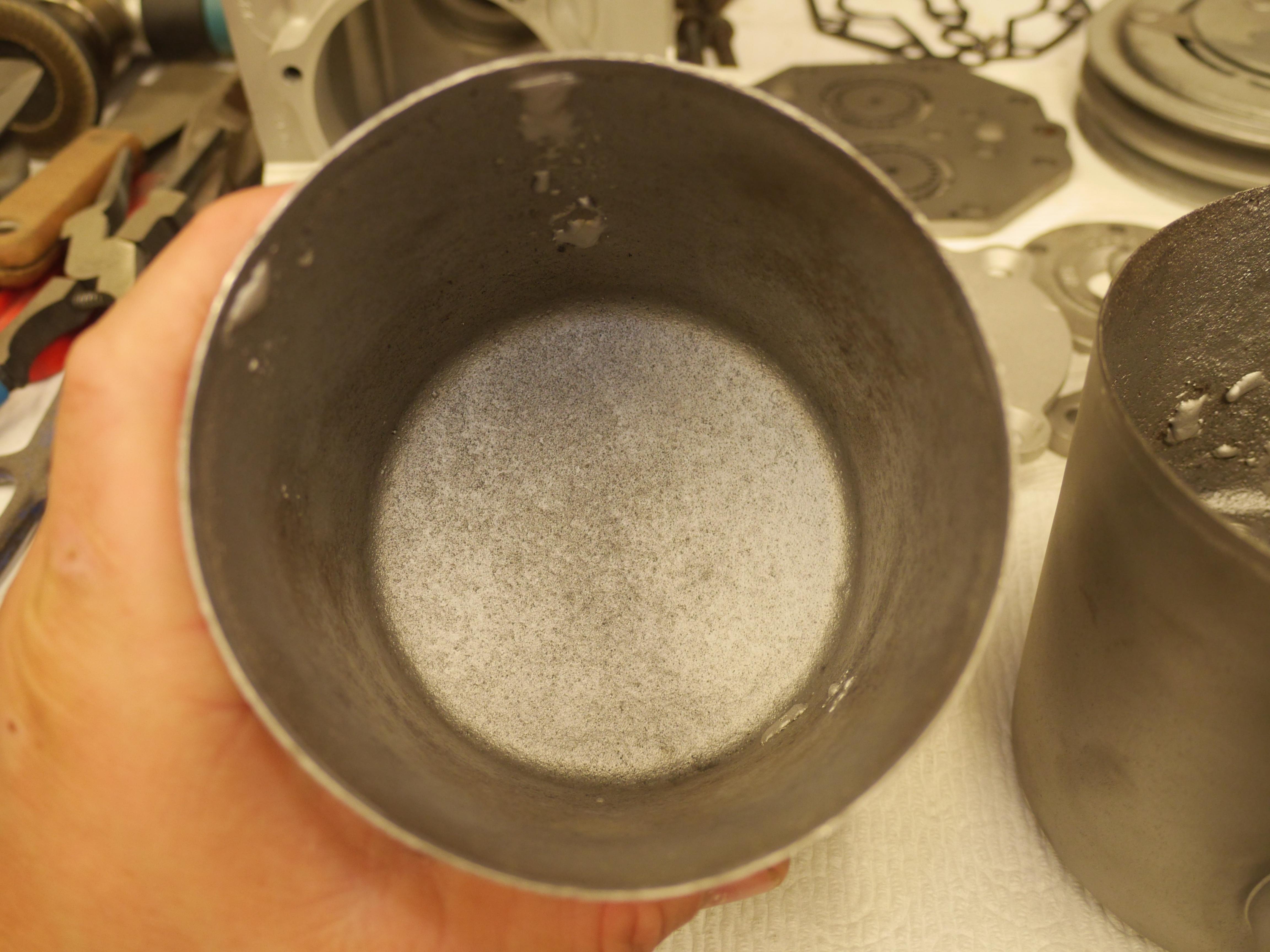
It took quite a number of attempts to get the entirety of the tank soldered up. Before I solder the tank back together, I decided to use an acid brush and paint the inside of the two tank halves with a toulene based gasoline resistant tank sealant. This was one of the worst fuel tanks I have ever tried to resurrect. It is going to take at least two coats of gas tank sealant to seal this one up.

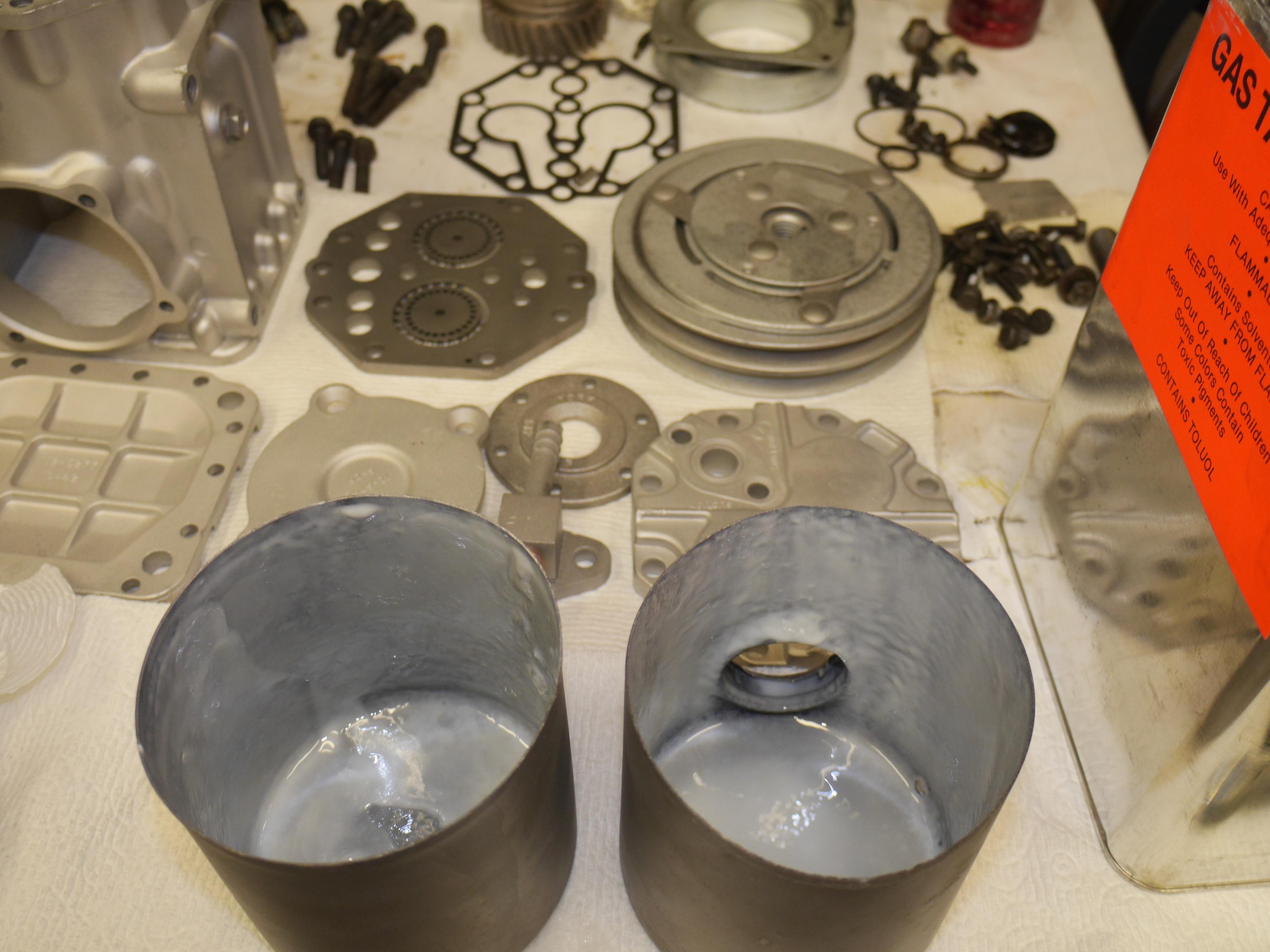
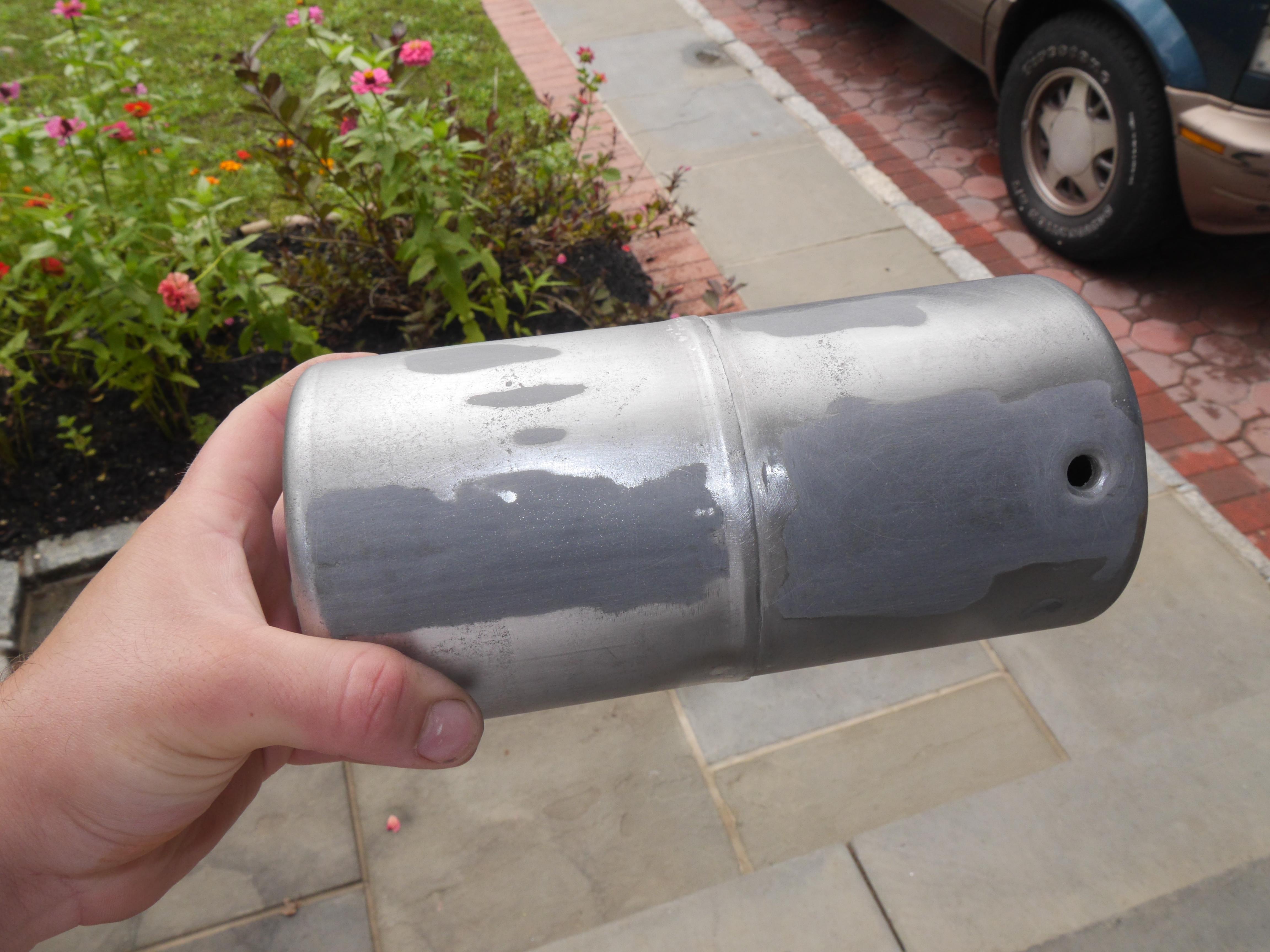
After the first coat of tank sealant dried, I soldered both halves of the tank together with a good old 60/40 leaded solder. Due to the large amount of solder used to seal the large holes in this tank up, I needed to spread a coat of JBweld over the soldered regions to get a smooth exterior finish. Once dry, I sanded the entire tank down and prepped it for paint.
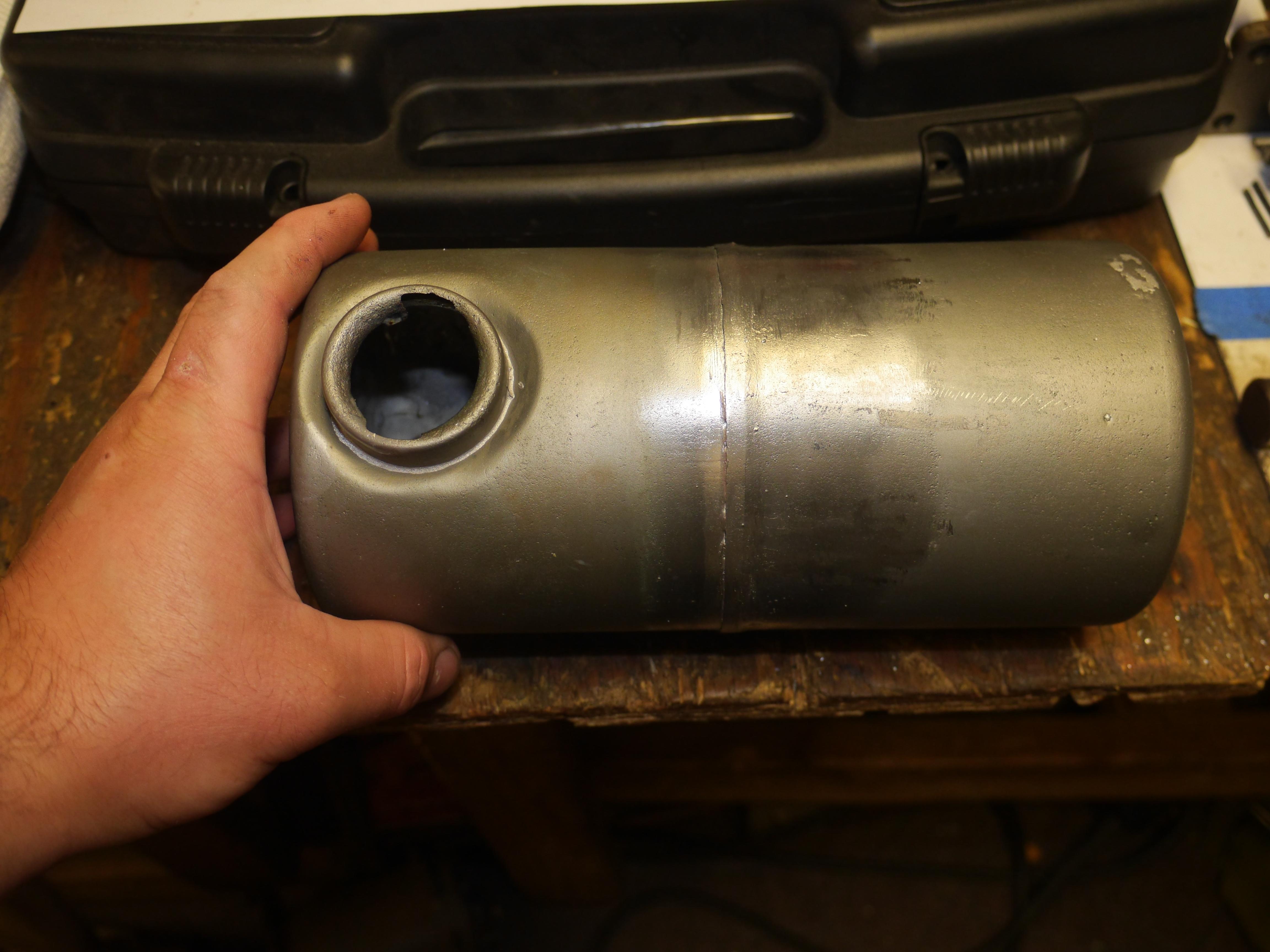
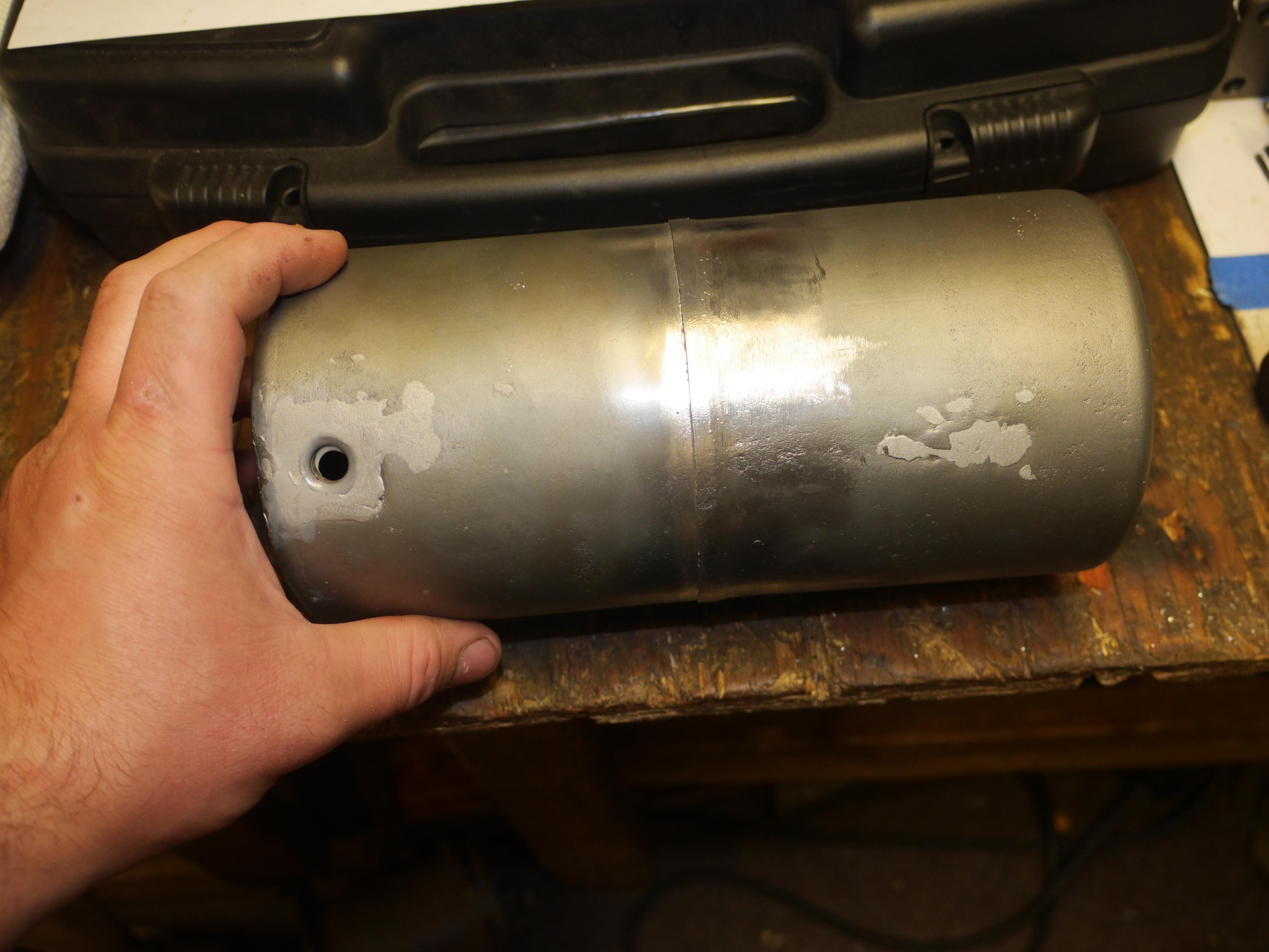
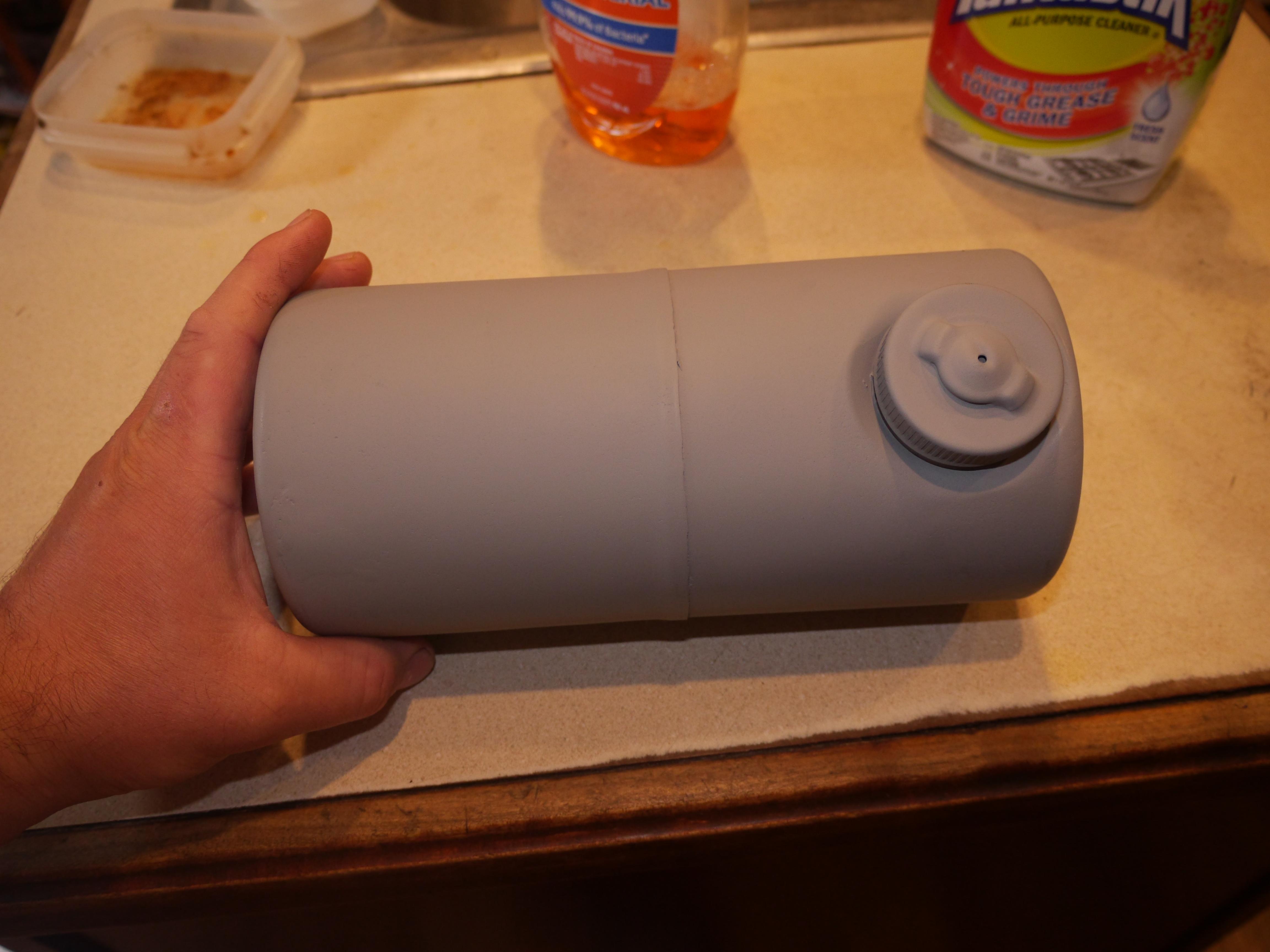
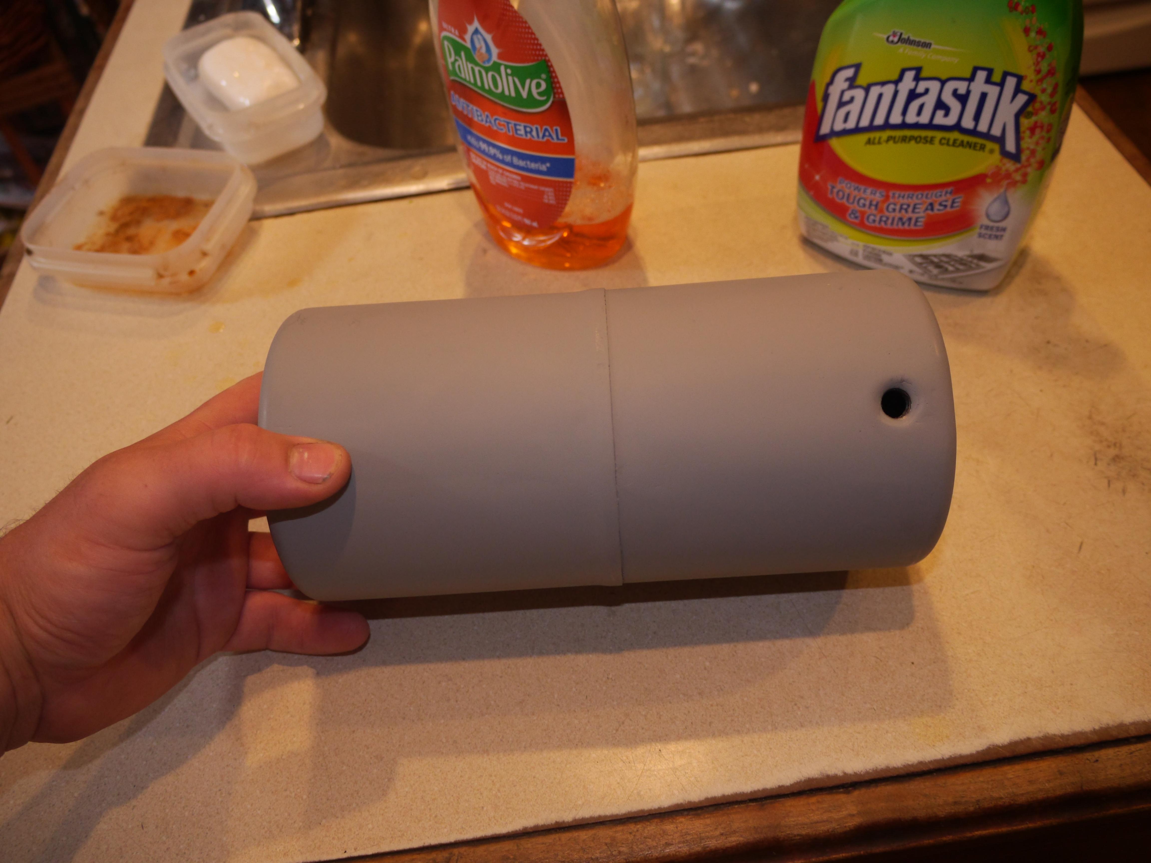
Once satisfied with the exterior finish of the tank, I primed it for paint. After three coats of primer, I decided to re-seal the inside of the tank with a second coat of toulene based gas tank sealant. This time it was a bit more tricky, since it is an anaerobic type sealant, and you have to keep swirling it around as to not pool in any particular spot. Several hours of turning later, the tank was re-sealed. Once the sealant is tacky enough that it does not run, I removed the fuel cap, and the drain, so that it could air dry. I like to let a sealed tank sit and air dry for at least a week before use.
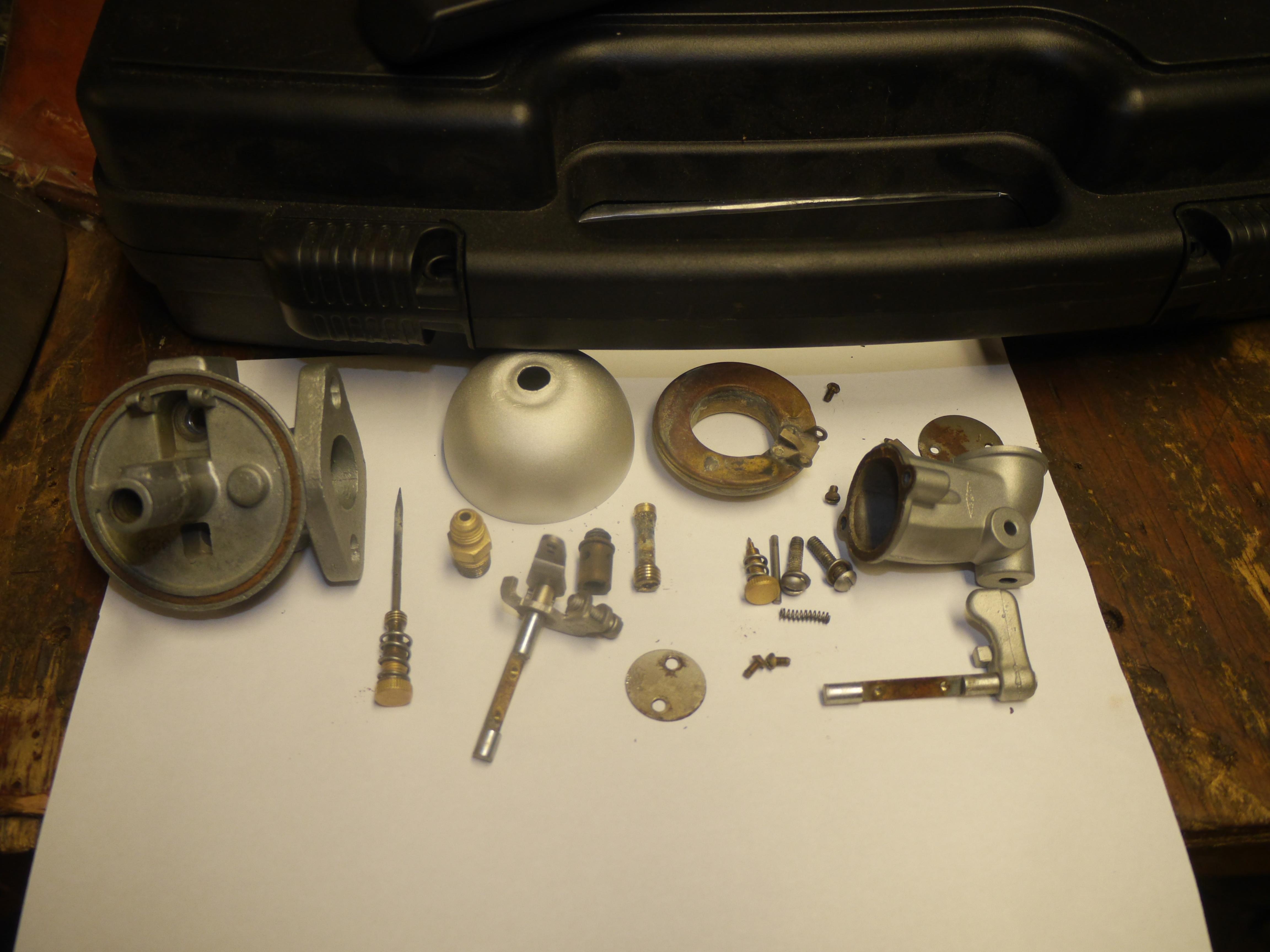
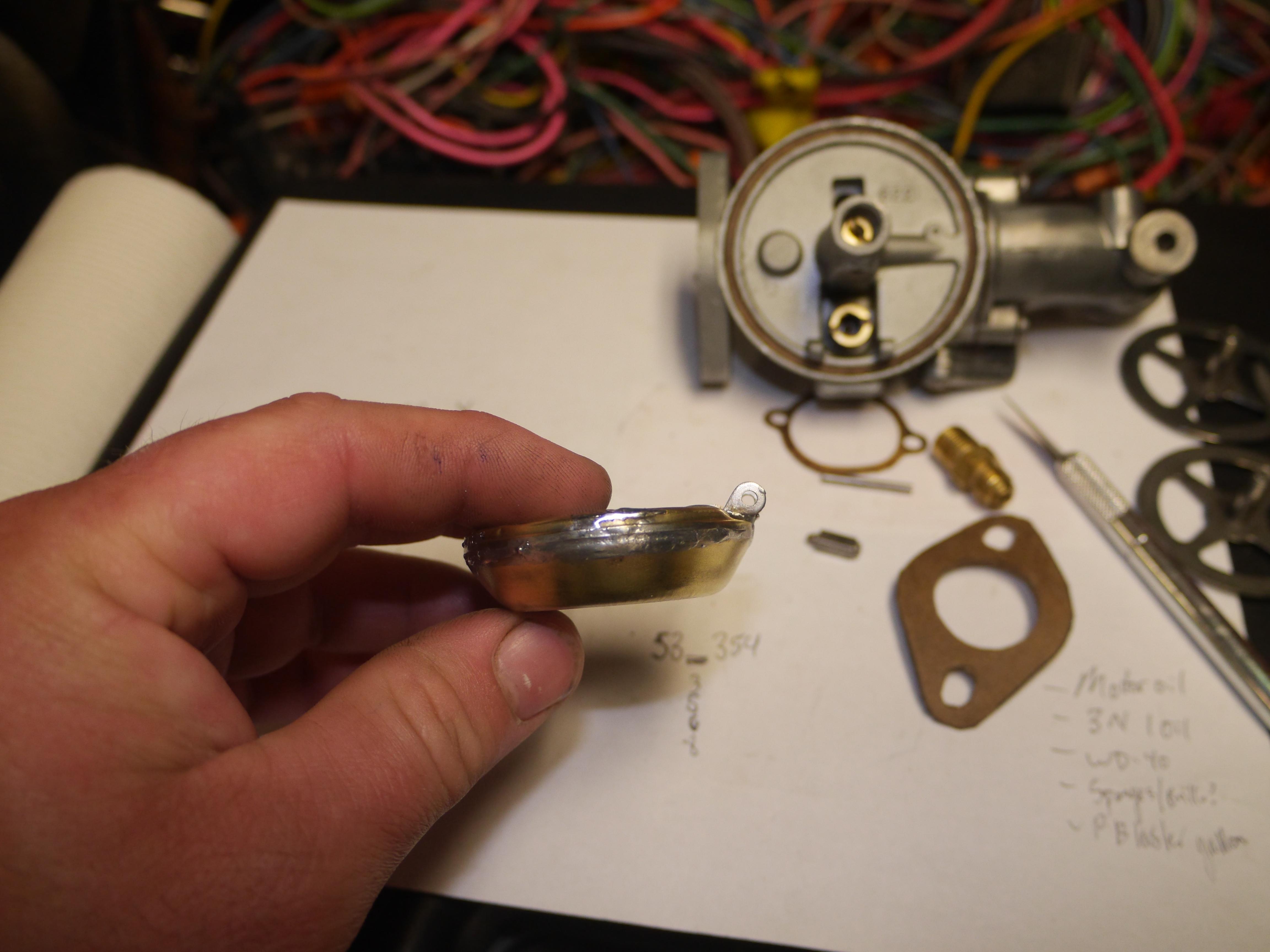
Now that the fuel tank is finished, I could focus on repairing the carburetor. The carburetor was for the most part complete, just in sad shape. The aluminum casting was pitted on the sealing surfaces, the float bowl was corroded, the float itself was full of holes, and the fuel metering valve needed to be resharpened. Thanks to my ultrasonic cleaner I was able to completely dismantle and clean the original carburetor so that it could be rebuilt with most of its original parts. Parts for these early Carter Model N carburetors are hard to find, so I did what was necessary to make it serviceable again, at least for a short while to see how well the engine runs.
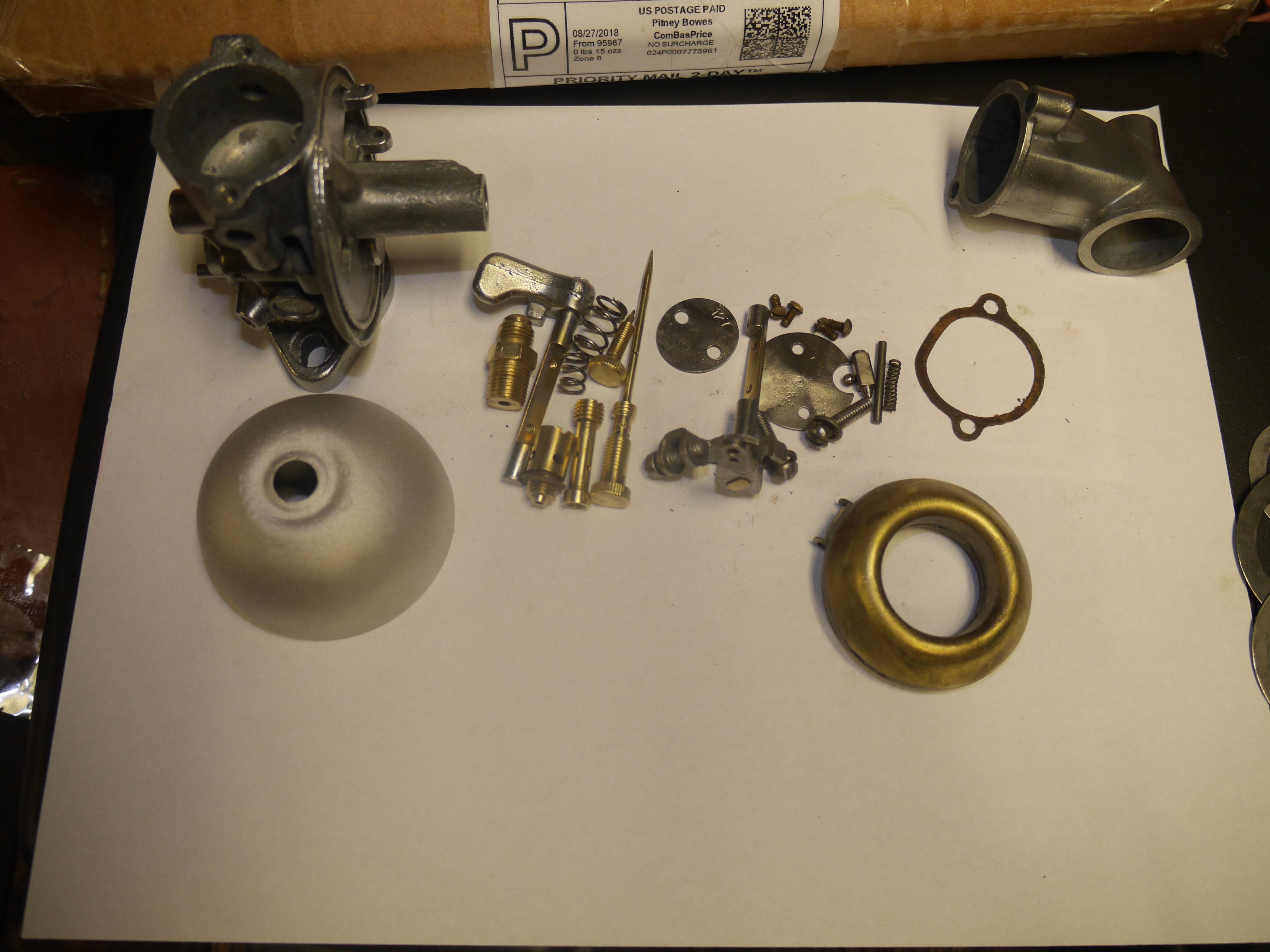
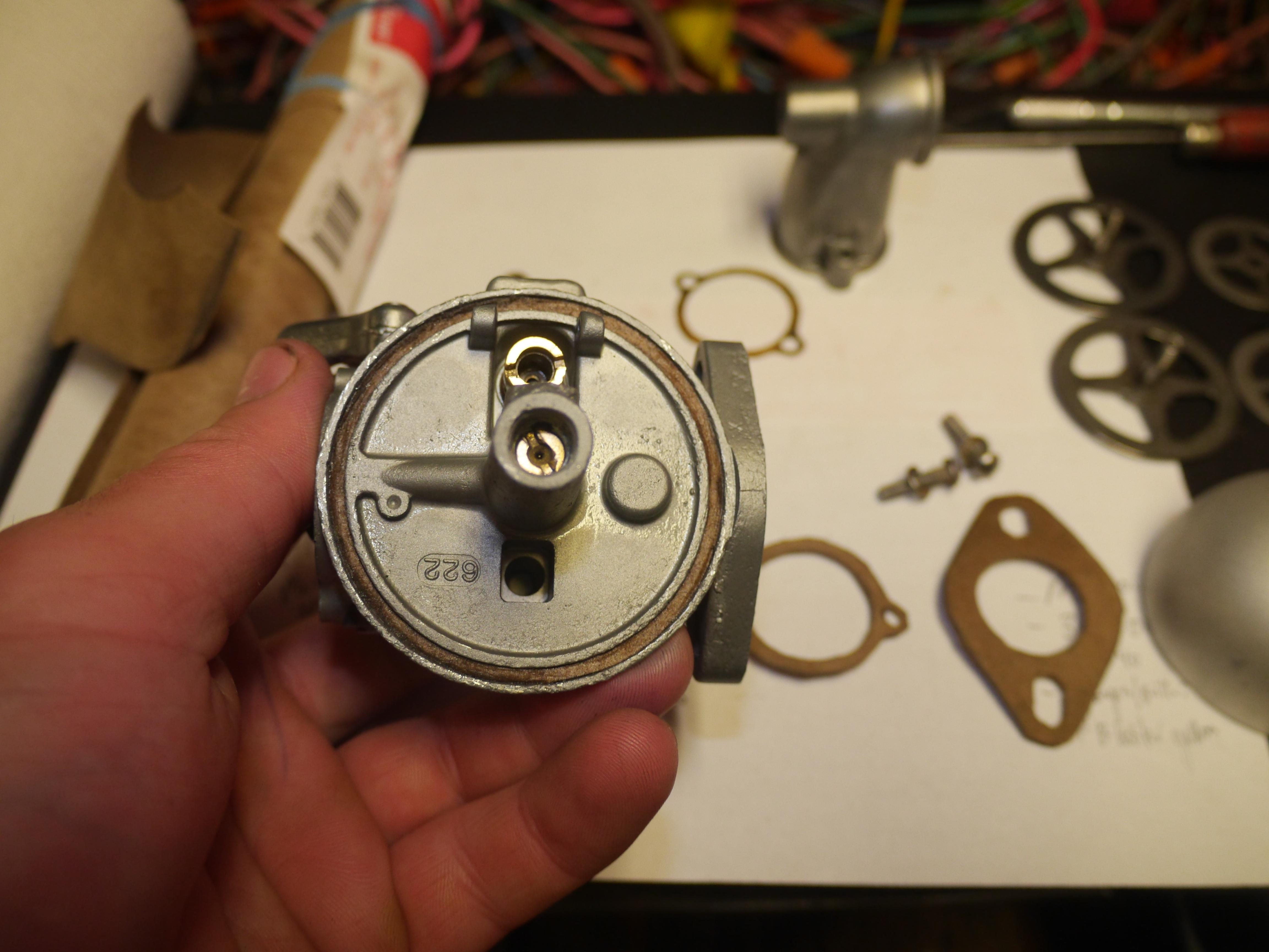
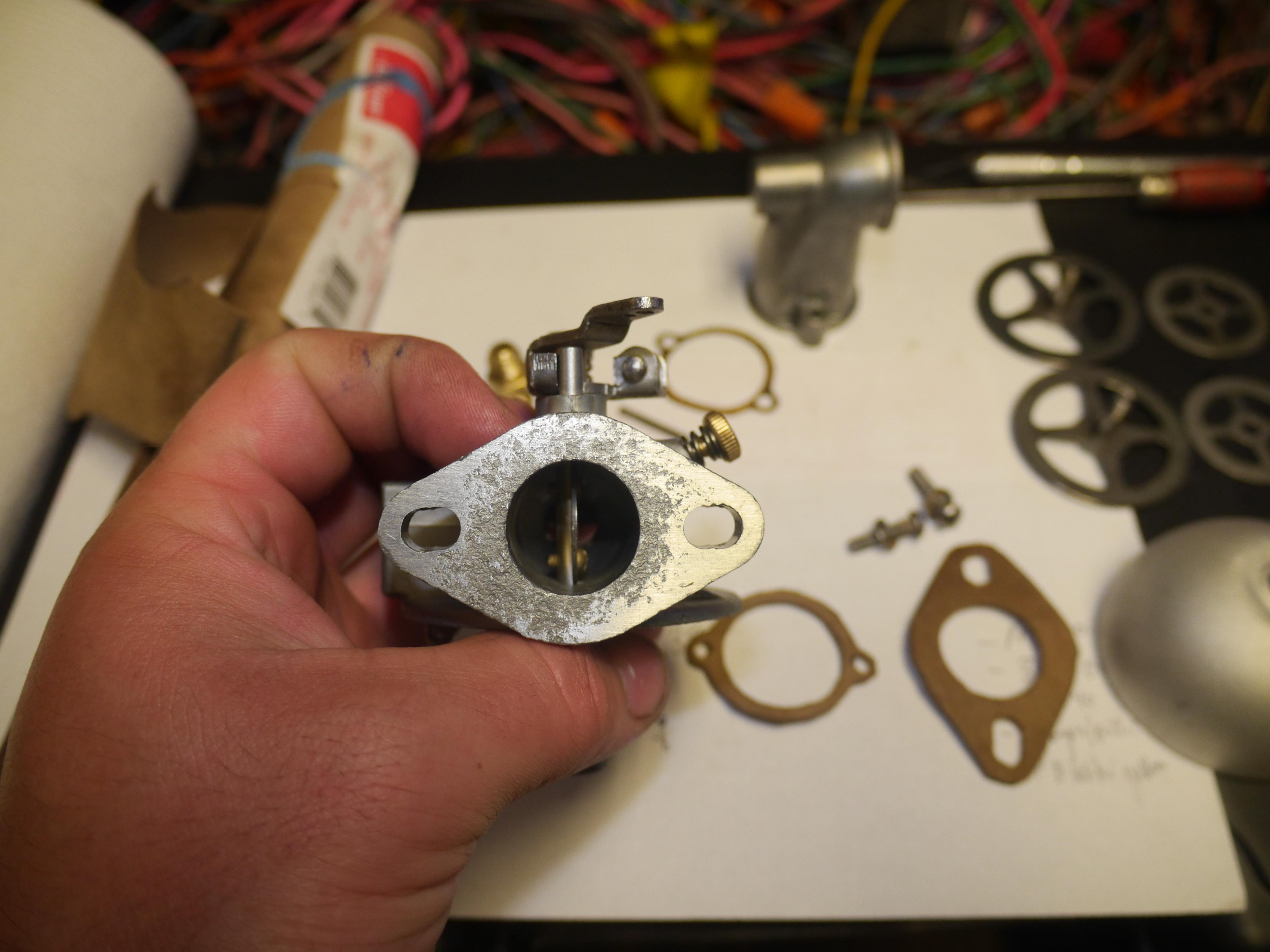
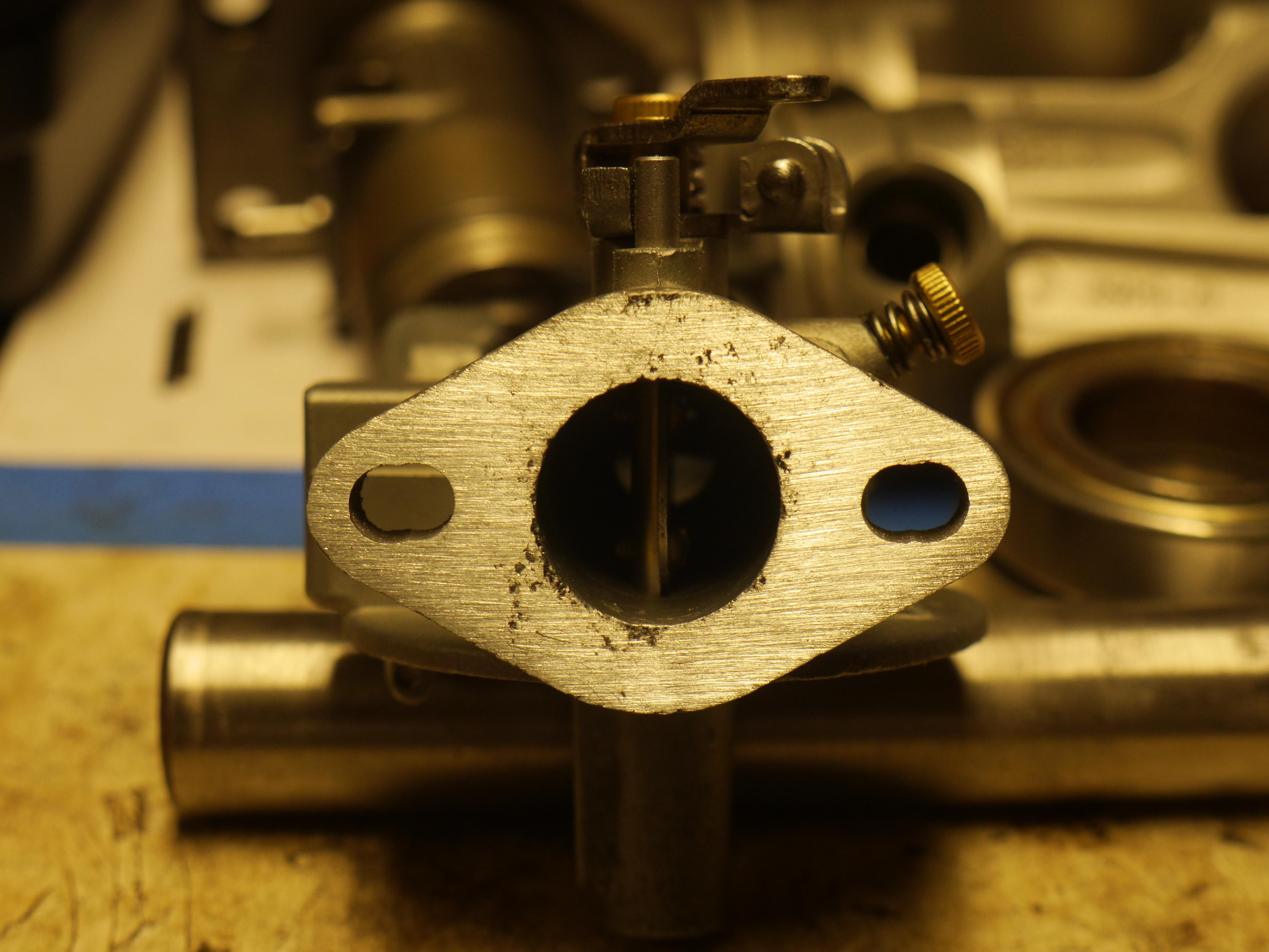
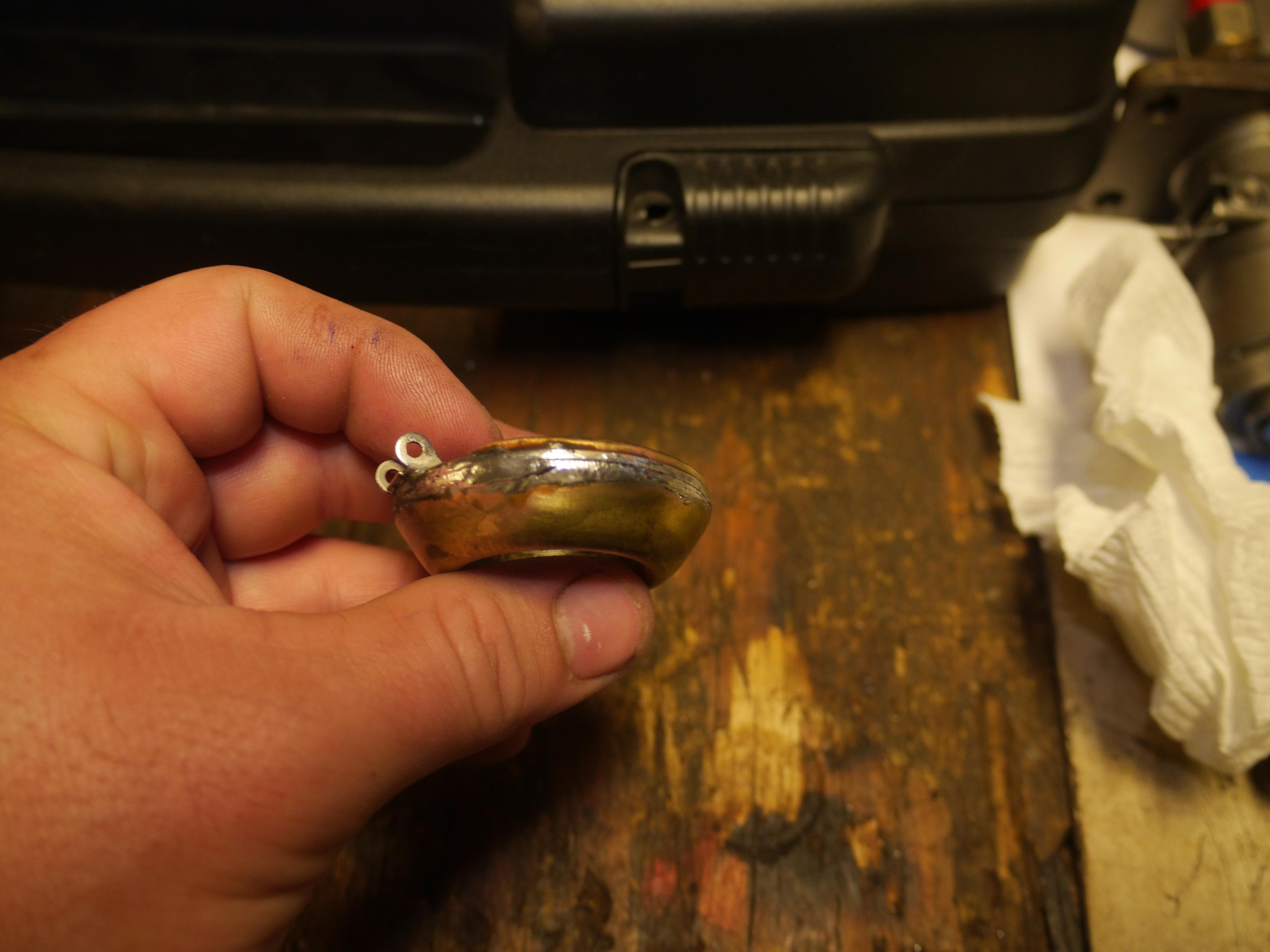
I had to plane the mounting face of the carburetor to remove most of the pitting that was present. Any substantial pitting can cause fuel to leak and air to be sucked into the engine resulting in poor performance. The biggest hurdle with the carburetor was the repair of the original tapered brass float. These floats are no longer available, and the modern replacements will not fit in these curved bowl Carter carburetors. I attempted to re-solder the float up on three different occasions and had varying degree of success. Finally I got fed up and completely removed all of the old solder so that I could completely re-solder the float in one go. I had much better results this time without having to worry about dis-similar solders being used. Soldering a float is tricky, as the heat from soldering expands the air inside of the float blowing the new solder out. Too much solder makes the float too heavy and it will not work properly. The key is to drill a small hole in the top of the float to let the air vent when soldering the large perimeter joints of the float. Once the inside and outside seams of the float are soldered up, make a pool of solder on the top of the float next to the vent hole. With one swoop, push the solder over the hole and let it cool. I test my floats in a bowl of boiling water. The success of your soldering can be seen almost instantly. Air will vent out of the float when submerged if there is a leak. Thankfully on the fourth attempt, the repaired float held just fine. No air bubbles to be found when submerged, and no water was taken on by the float.

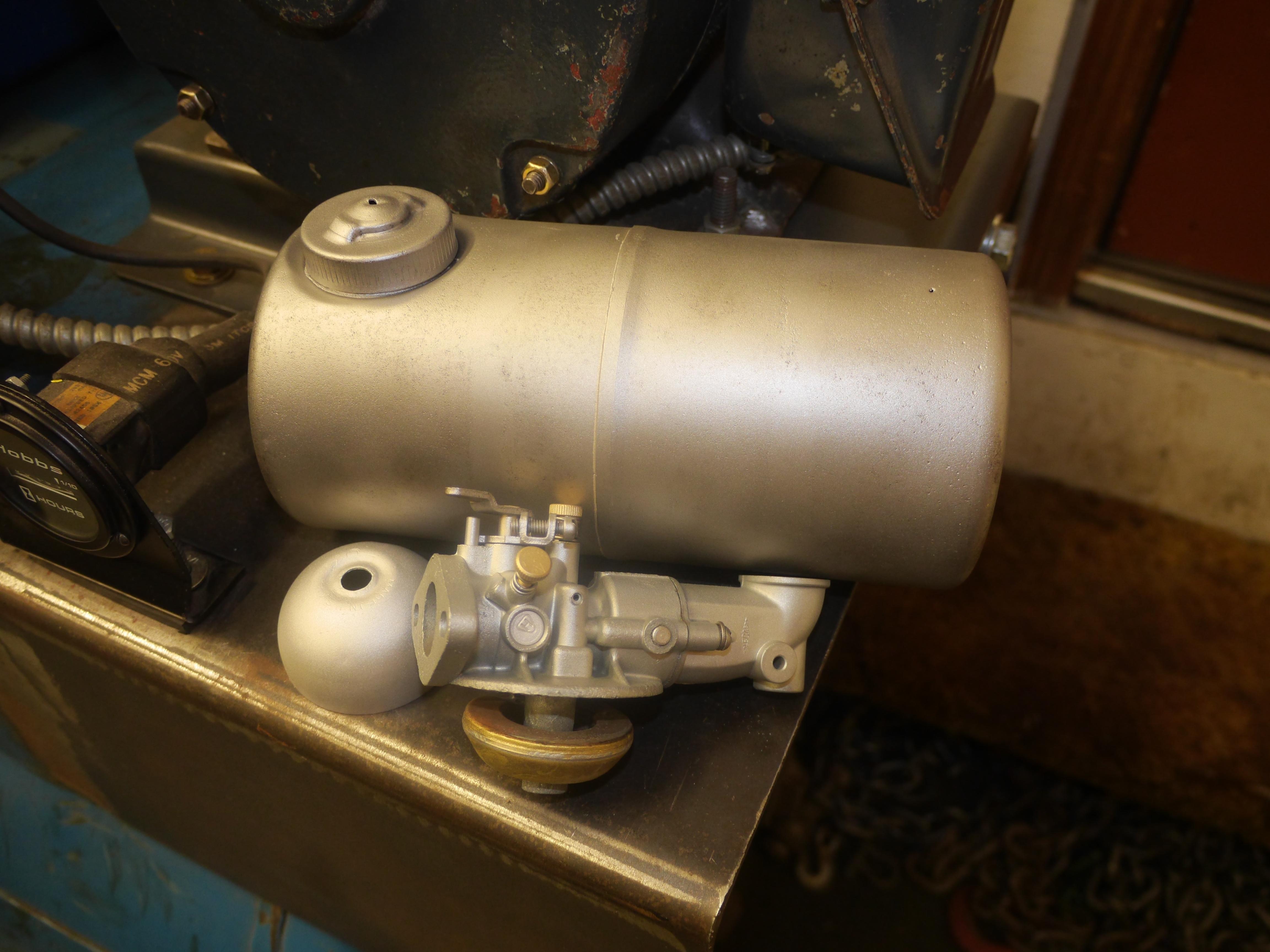
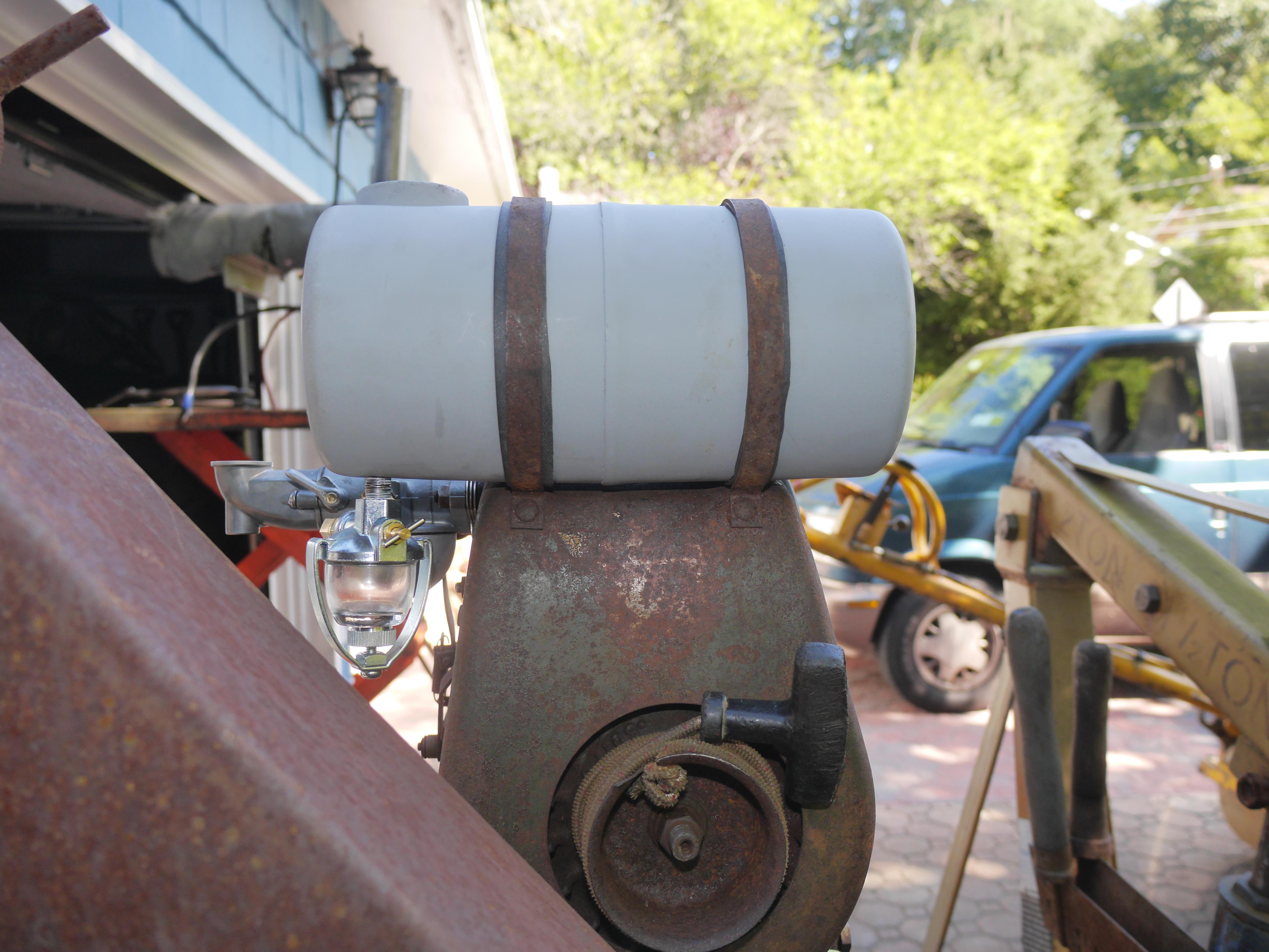
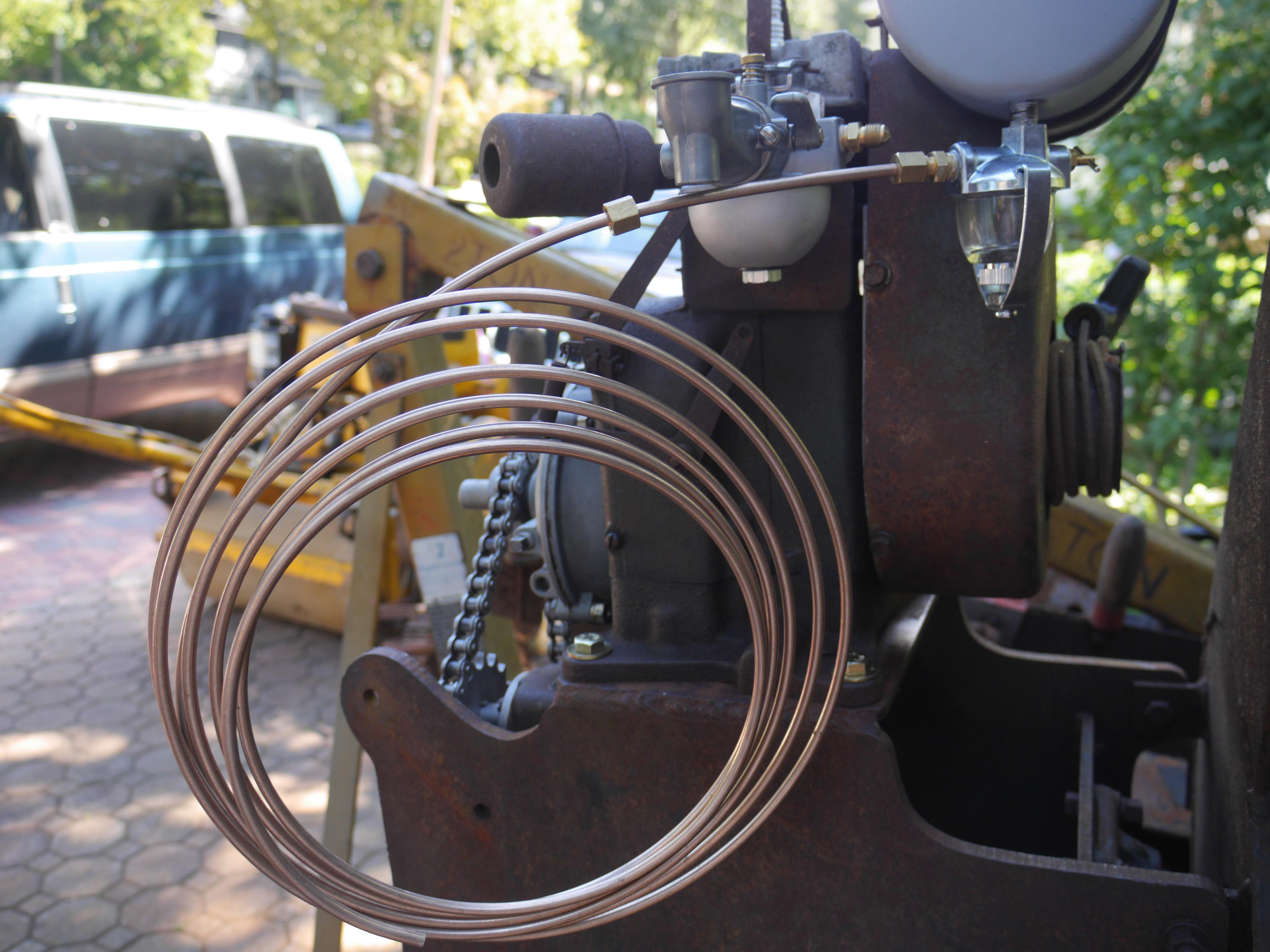
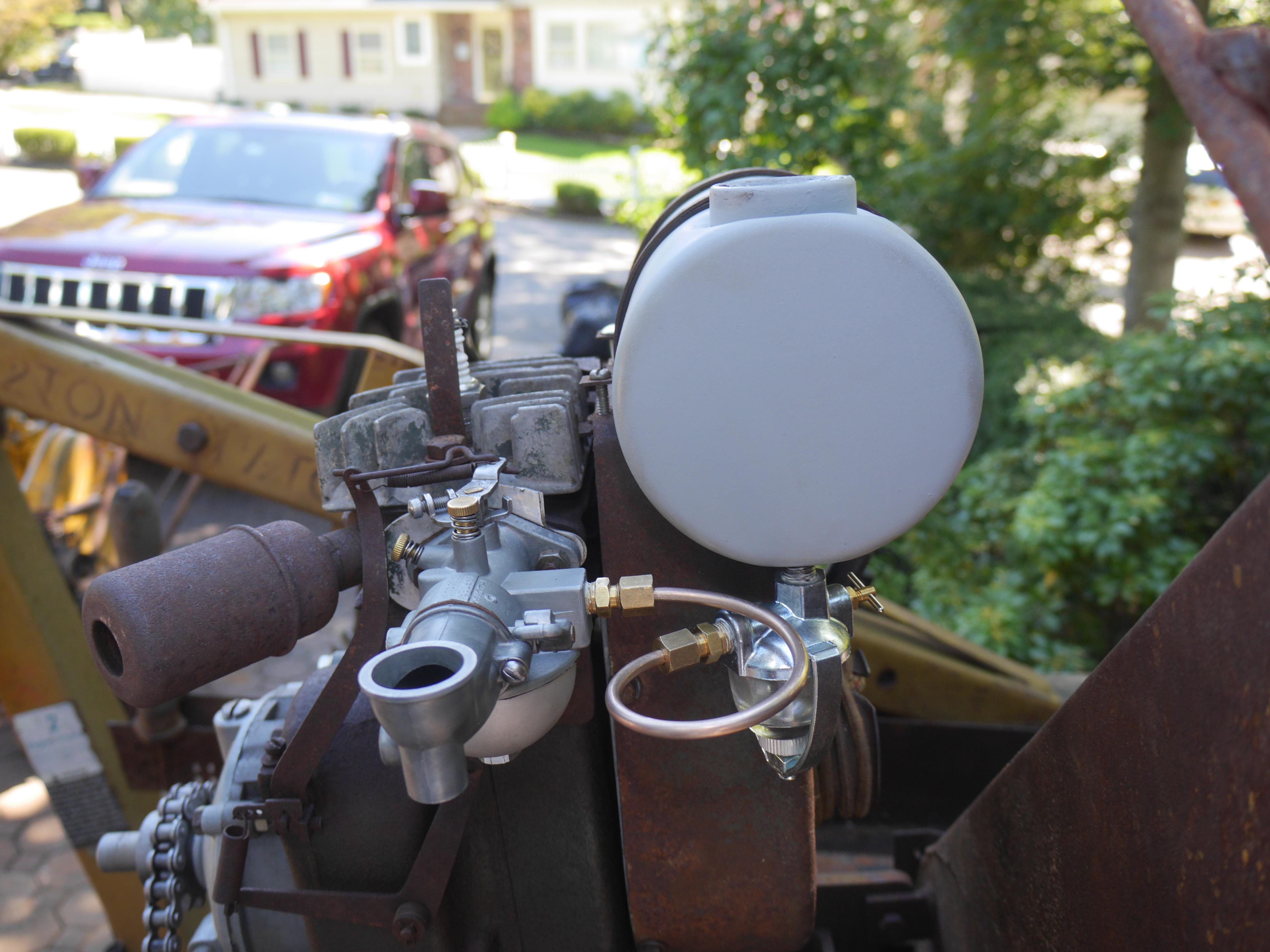
I finished reassembling the original carburetor with some new home made gaskets, and mounted the carburetor back on the engine. I took this opportunity to mount the original now fully repaired fuel tank back on the engine. I cut two long narrow strips of medium durometer rubber to make some insulative supports for the fuel tank. The rubber should minimize vibrations and keep water from pooling between the steel tank straps and the fuel tank. The original fuel line and valve were completely shot and could not be used, so I added a new sediment bowl and made up a new 1/4" fuel line out of some left over cunifer I had. Simple compression fittings on either end make a good seal.

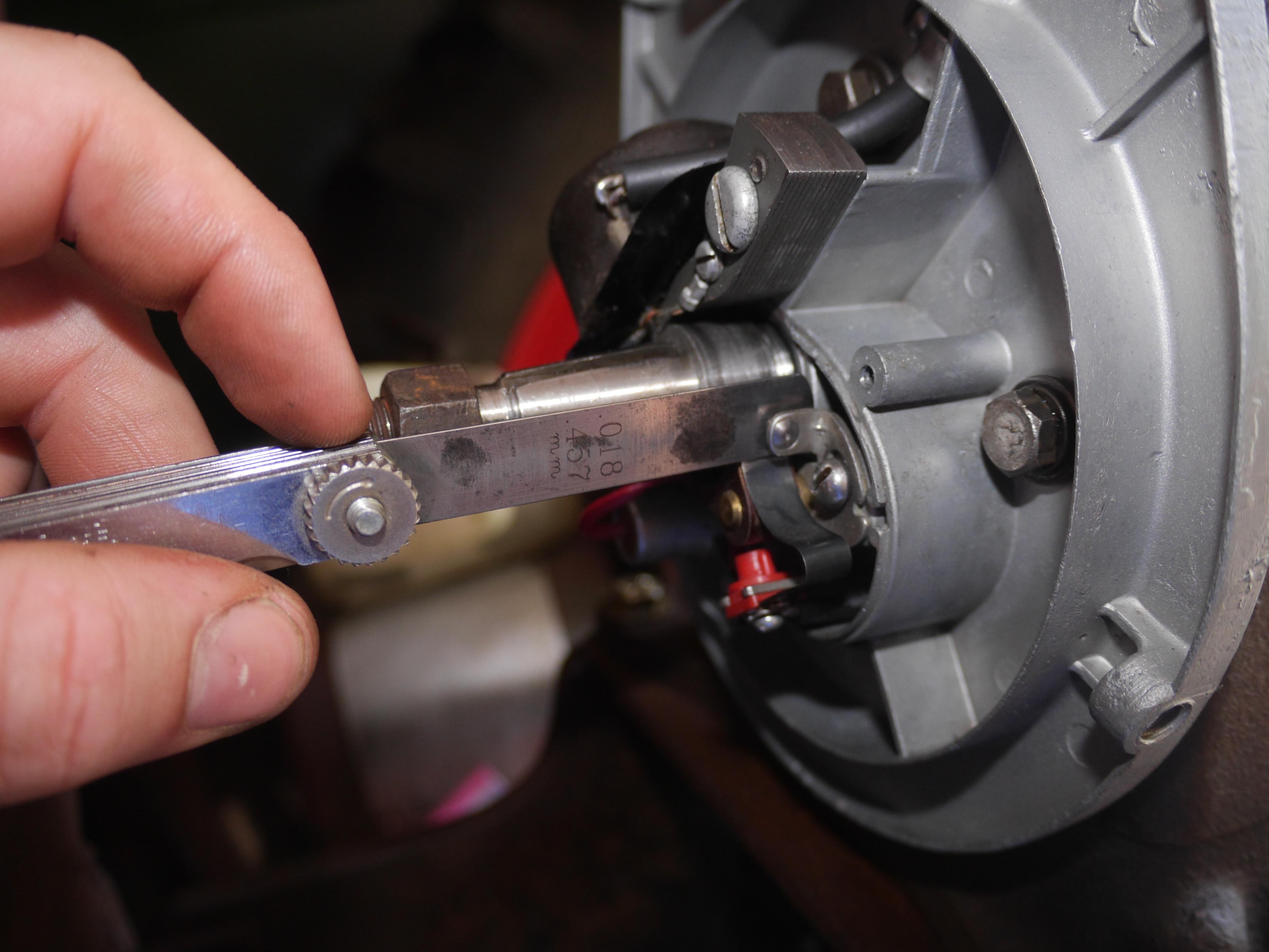
Now that the engine is complete, it is ready to run. I poured some fuel in the tank, filled the crankcase with Rotella T1 SAE 30 motor oil, and gave the cord a pull. With the points set at 0.018" the engine started up but ran absolutely awful. I knew the points were bad so I advanced the timing a bit with the points set at 0.014" and the engine ran much better. However you can still hear the ignition coil cutting out at high rpm in this video. You might notice that the axle is not present in the video, so now I will provide you with an update on that.
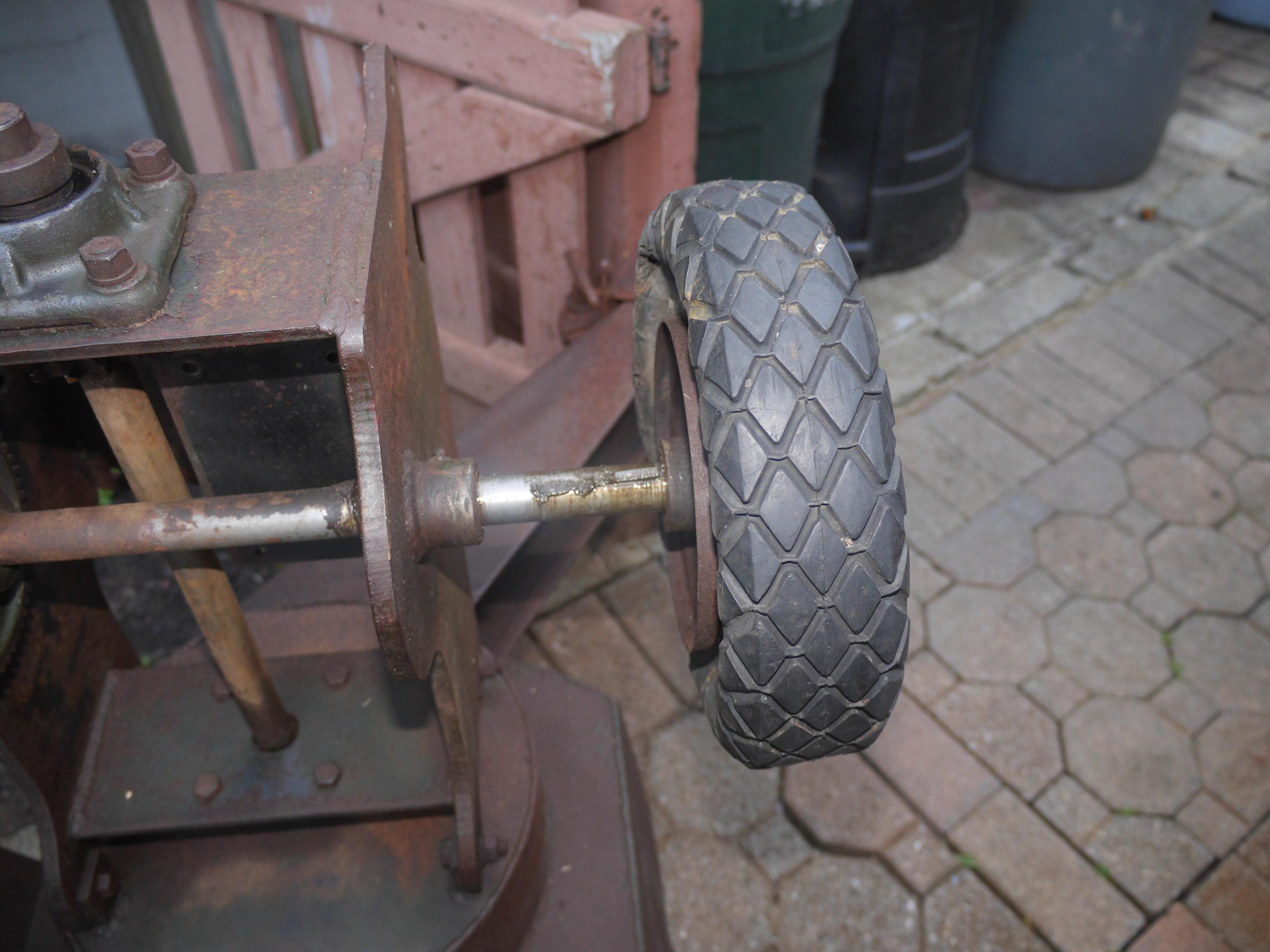
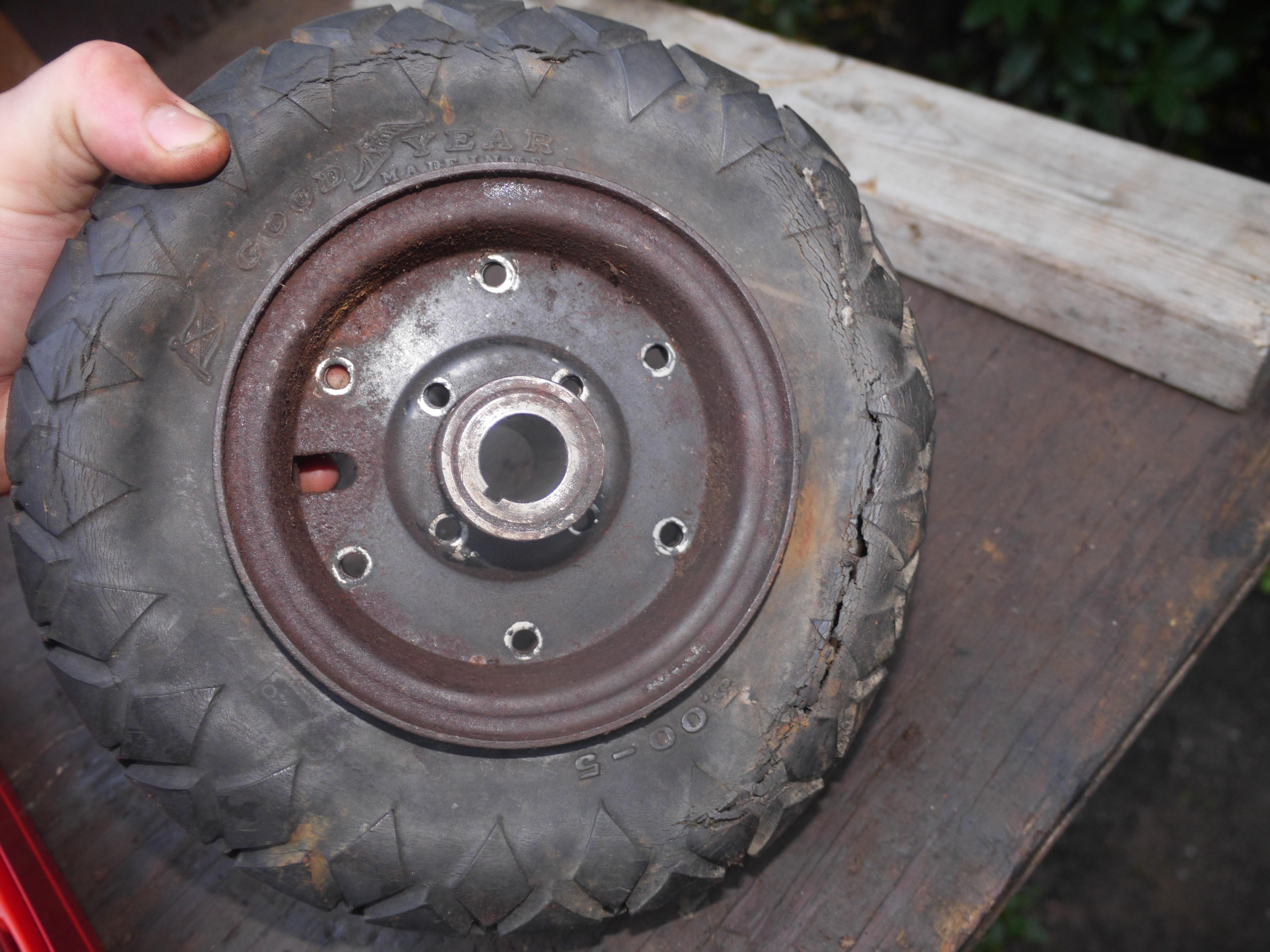
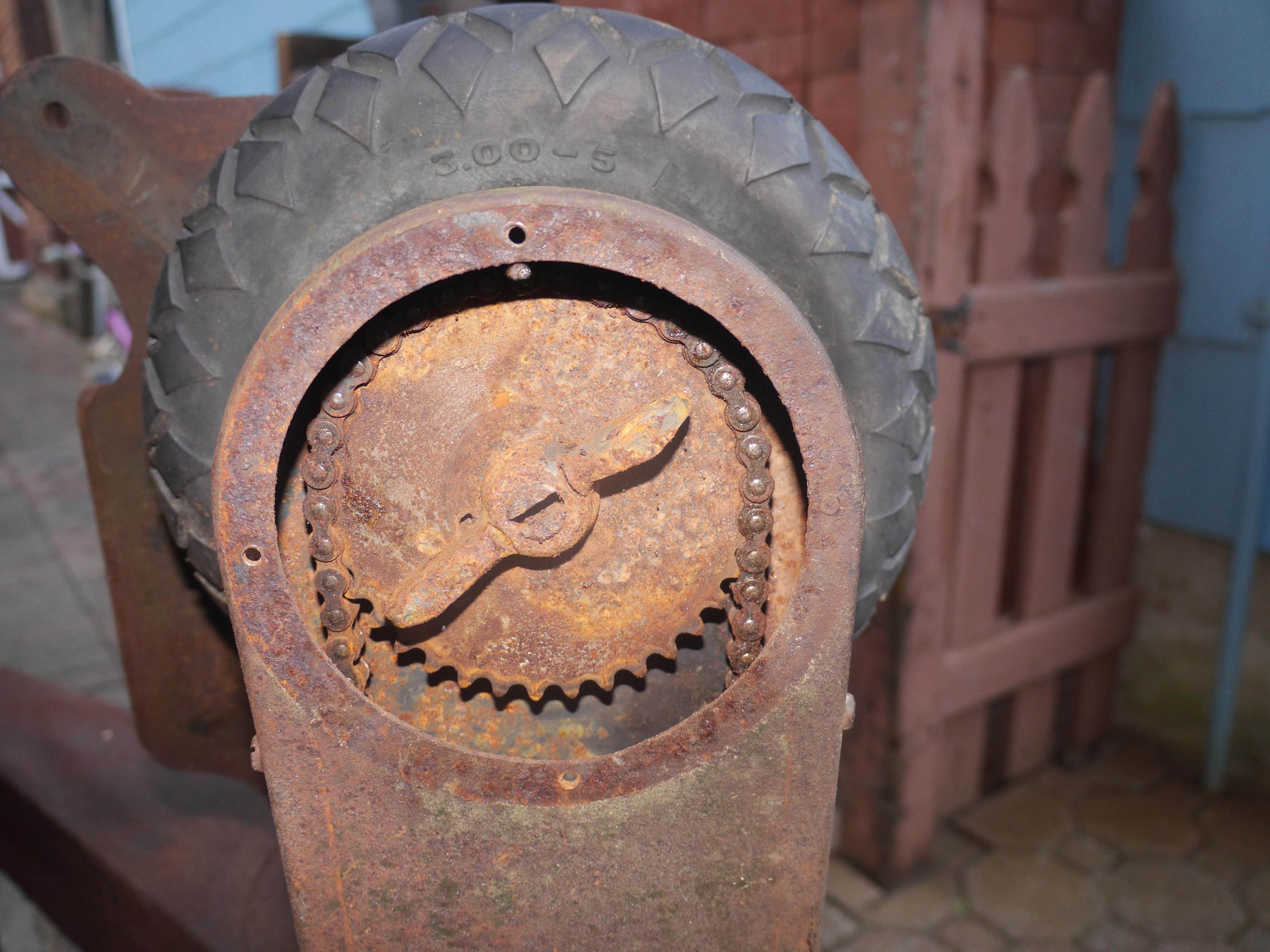
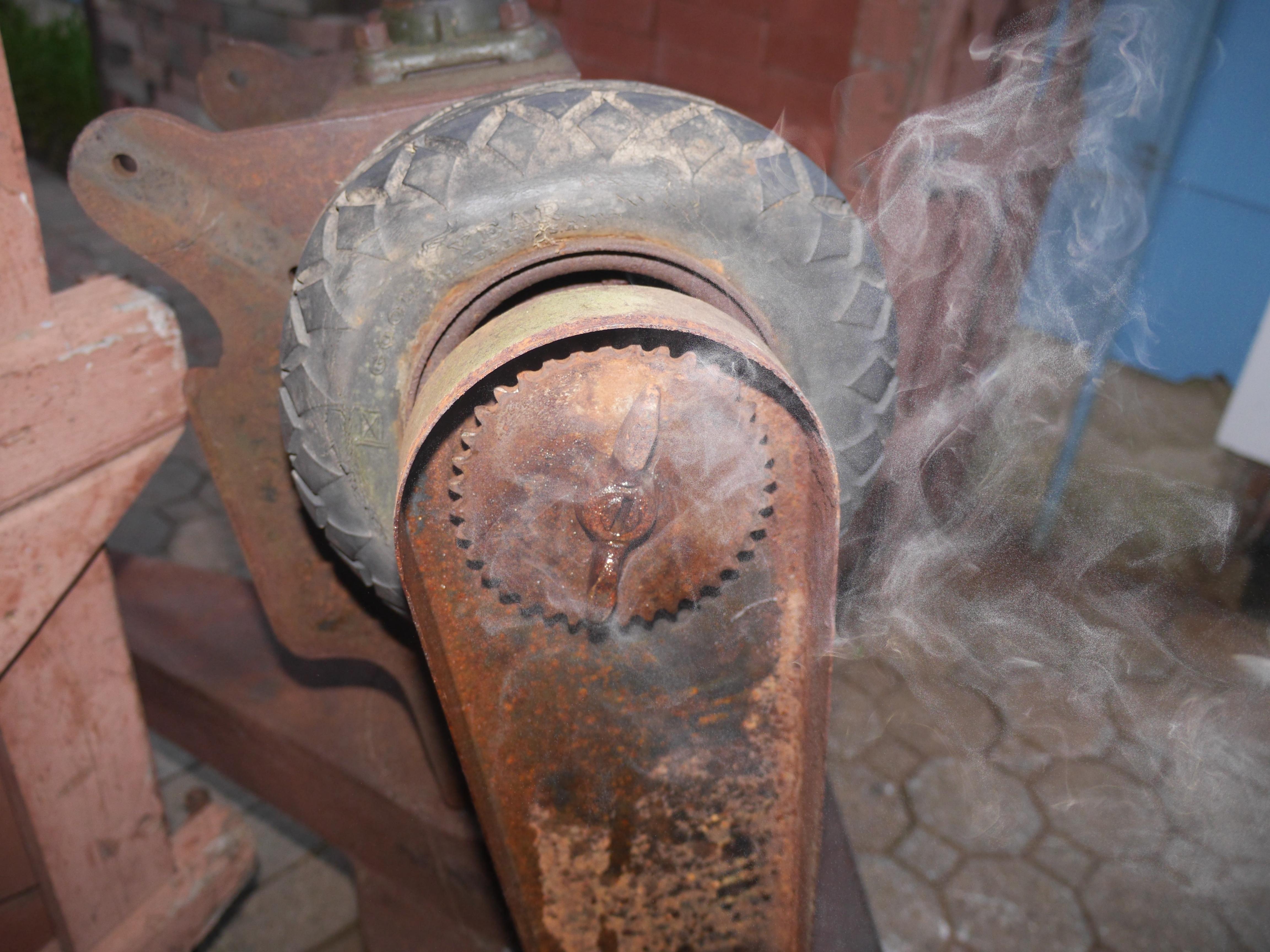
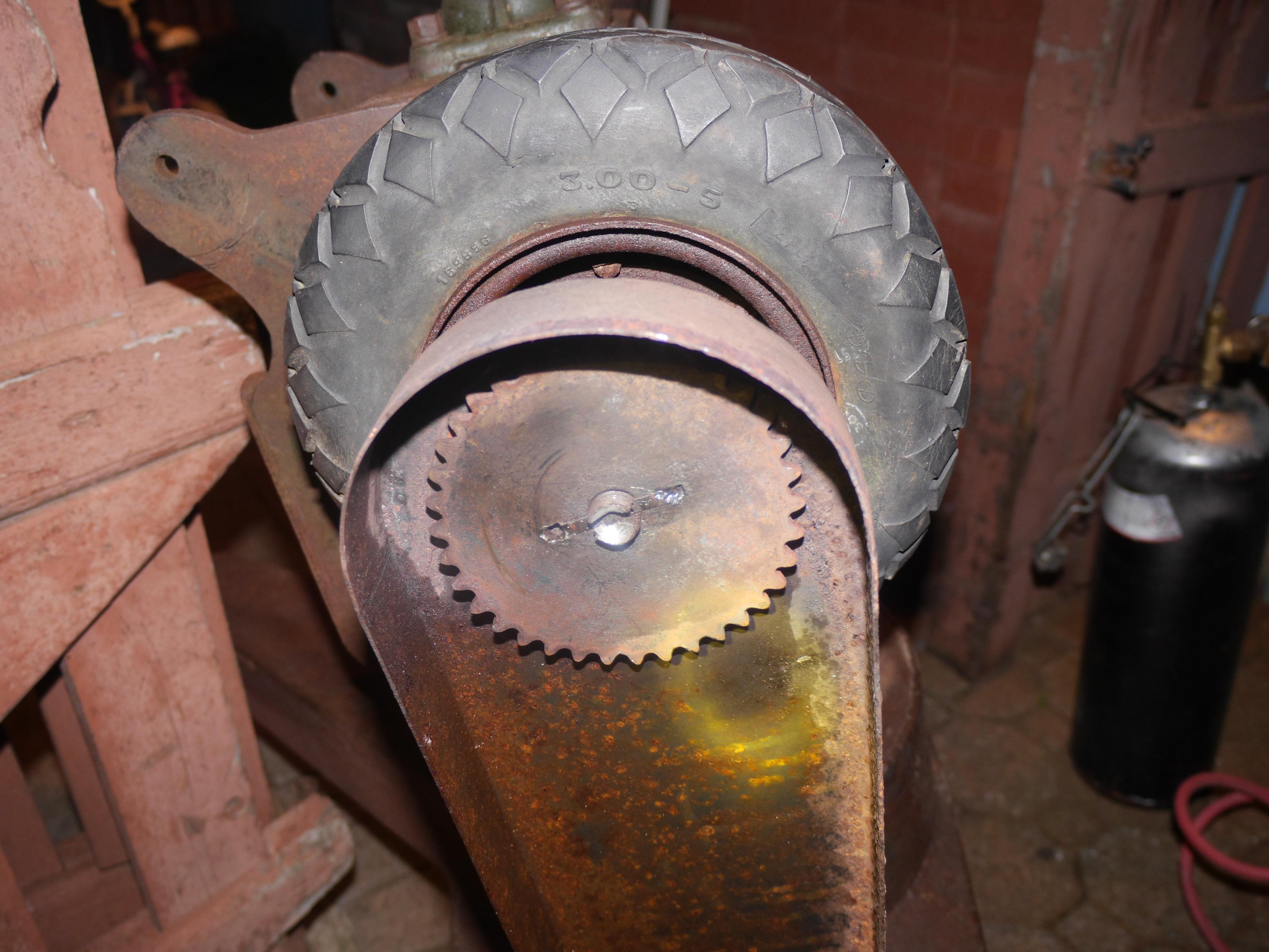
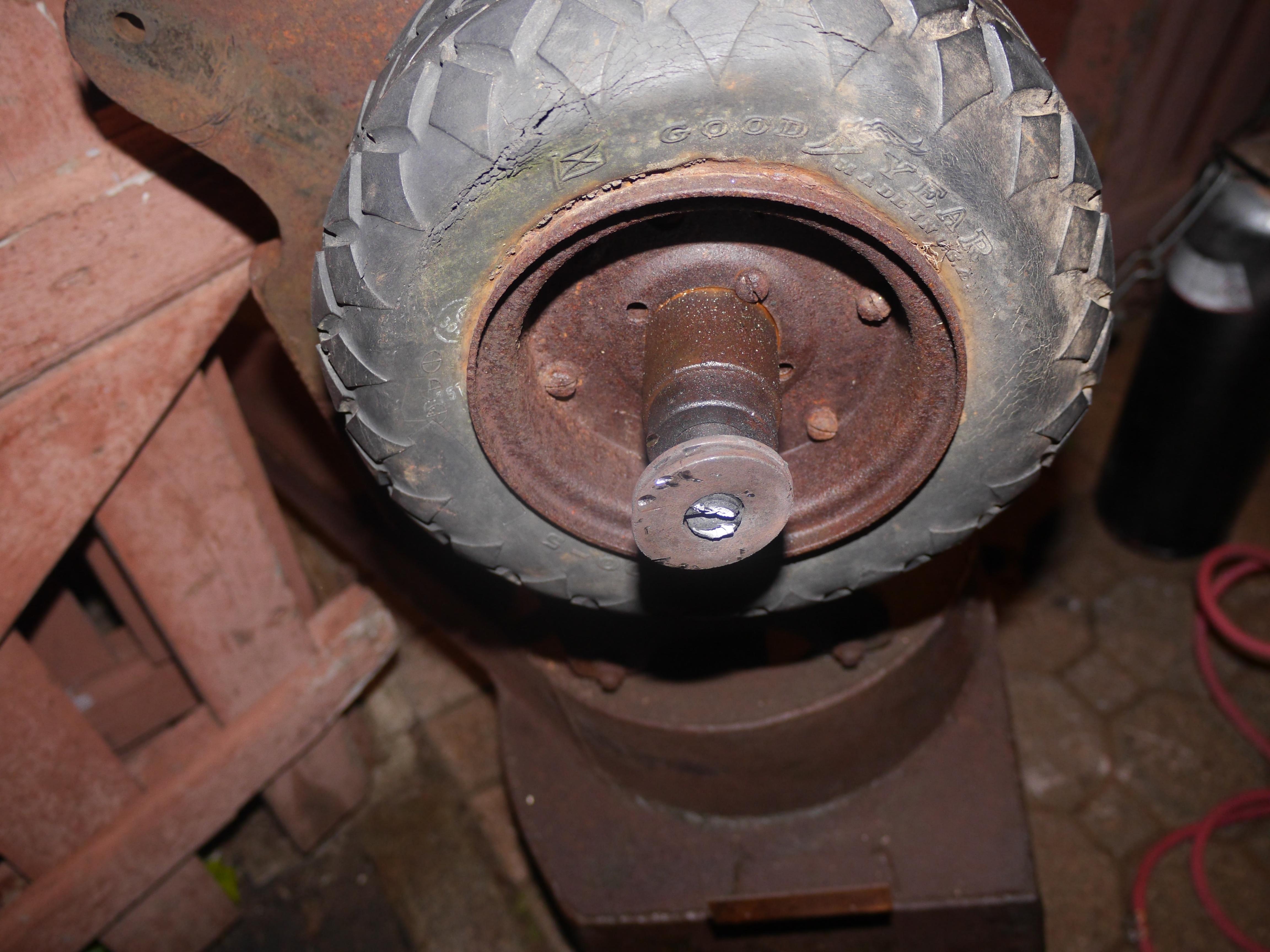
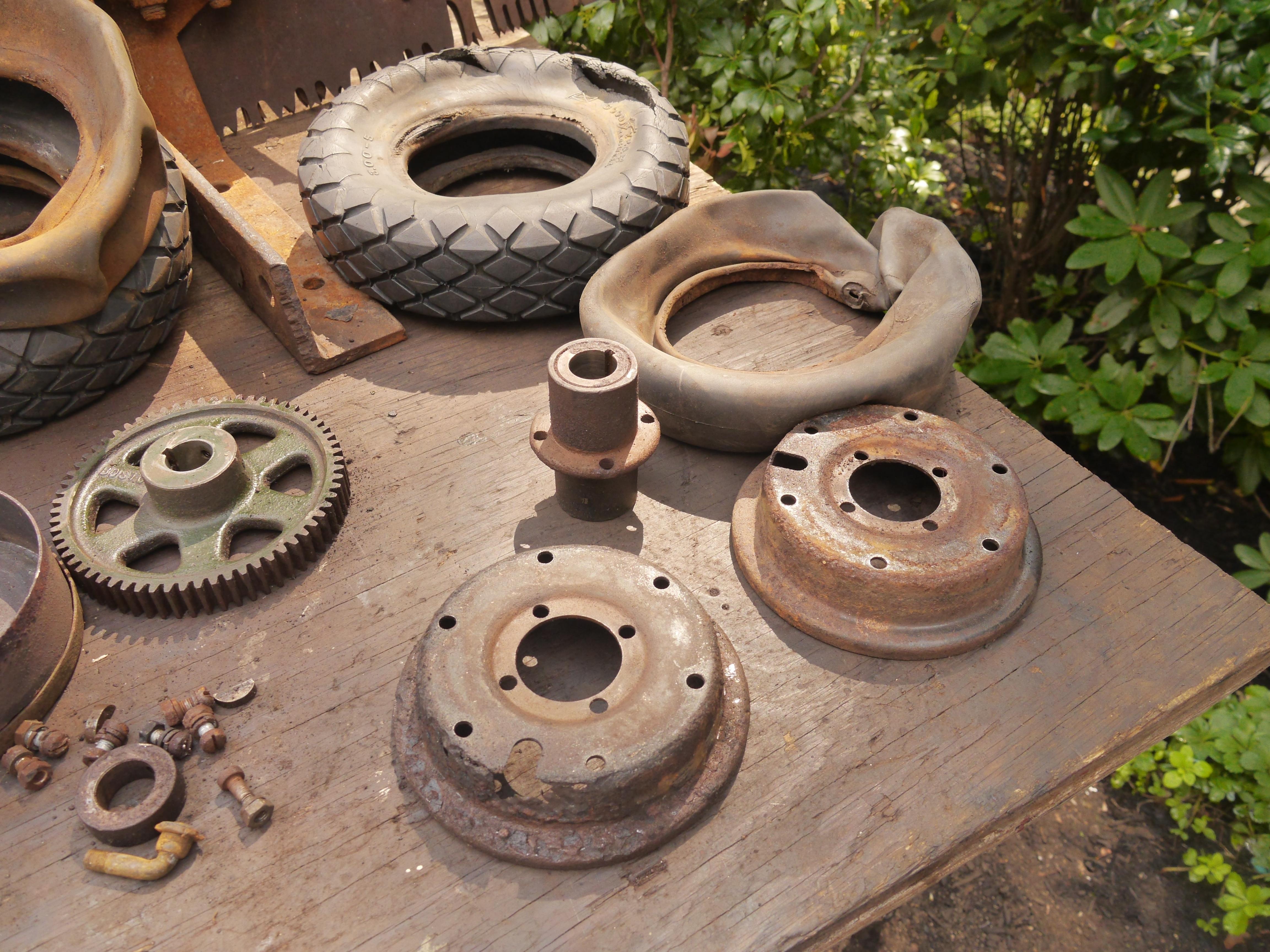
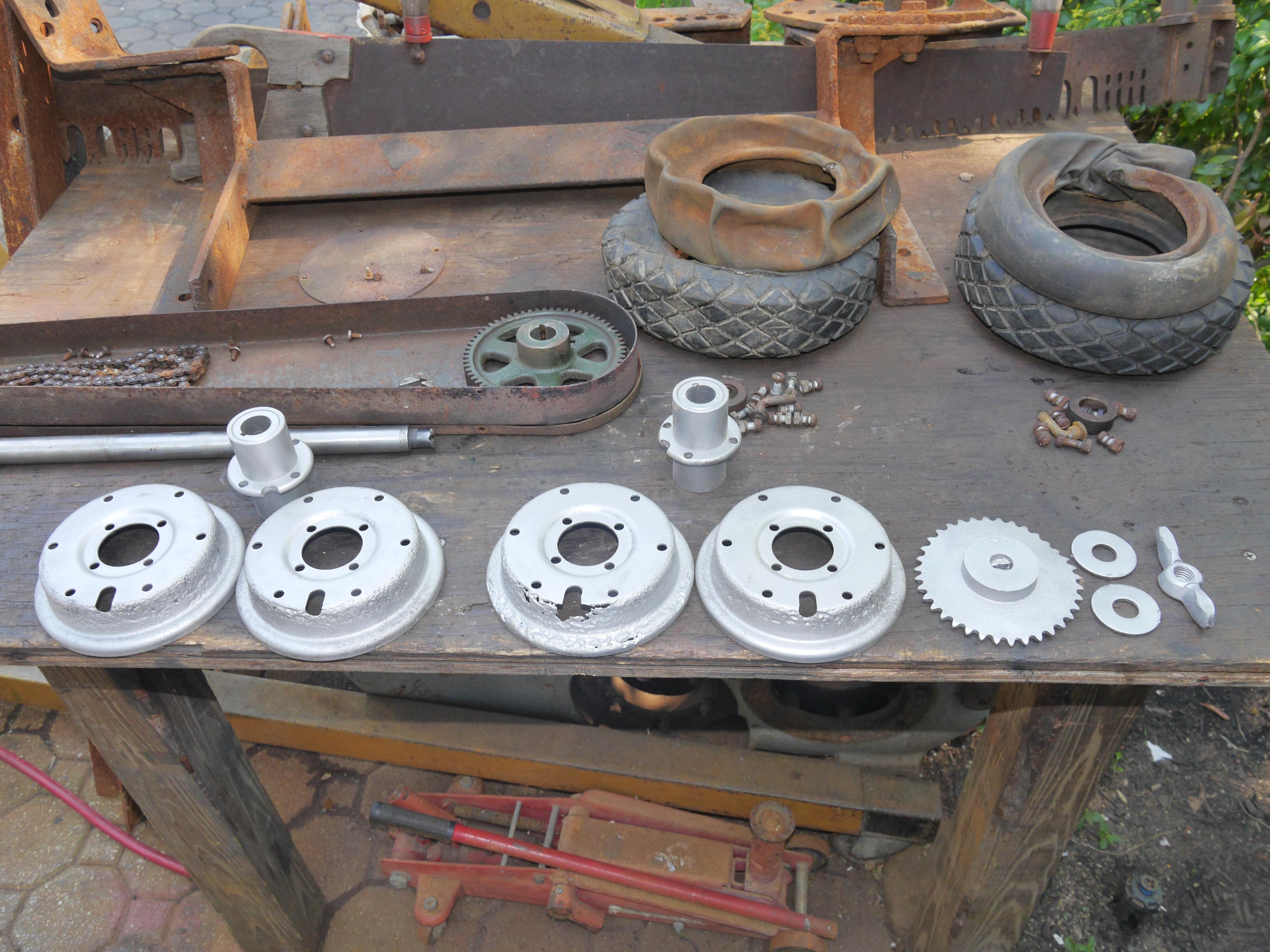
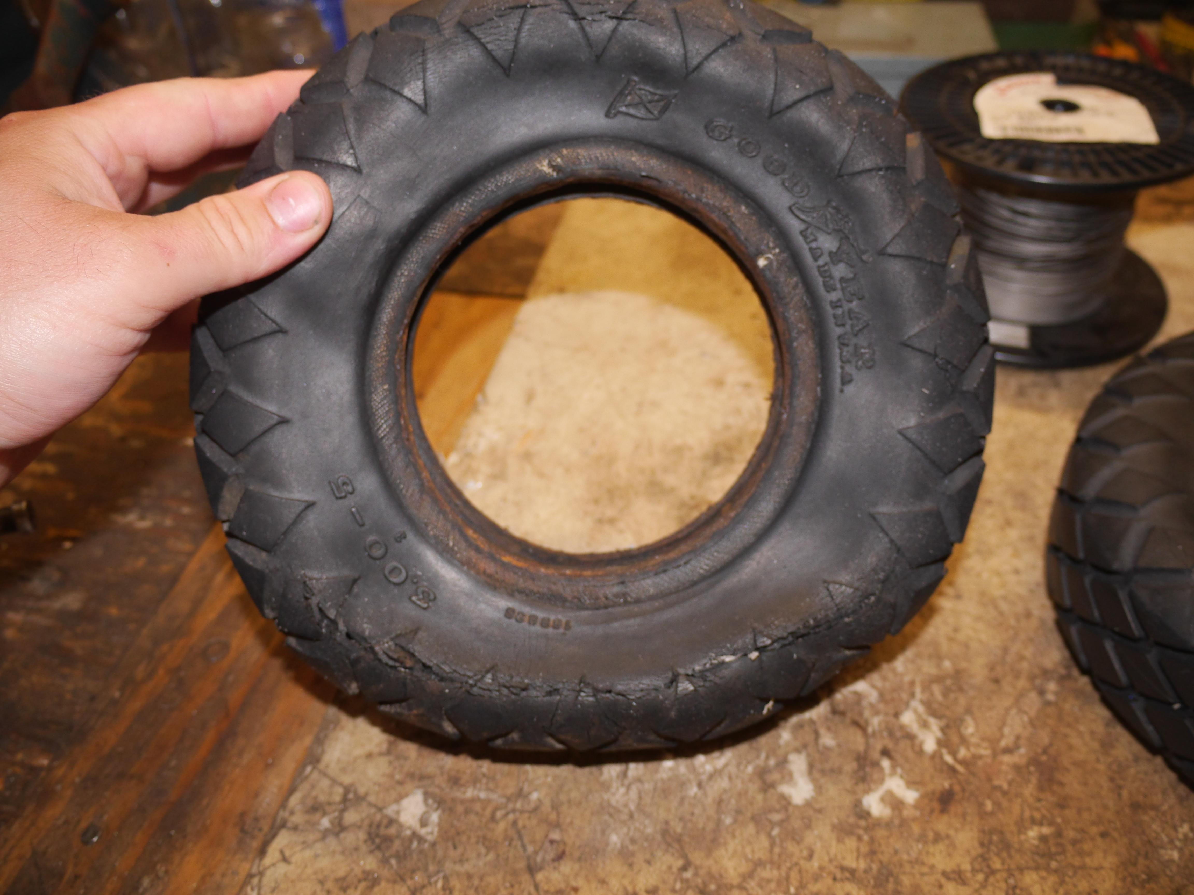
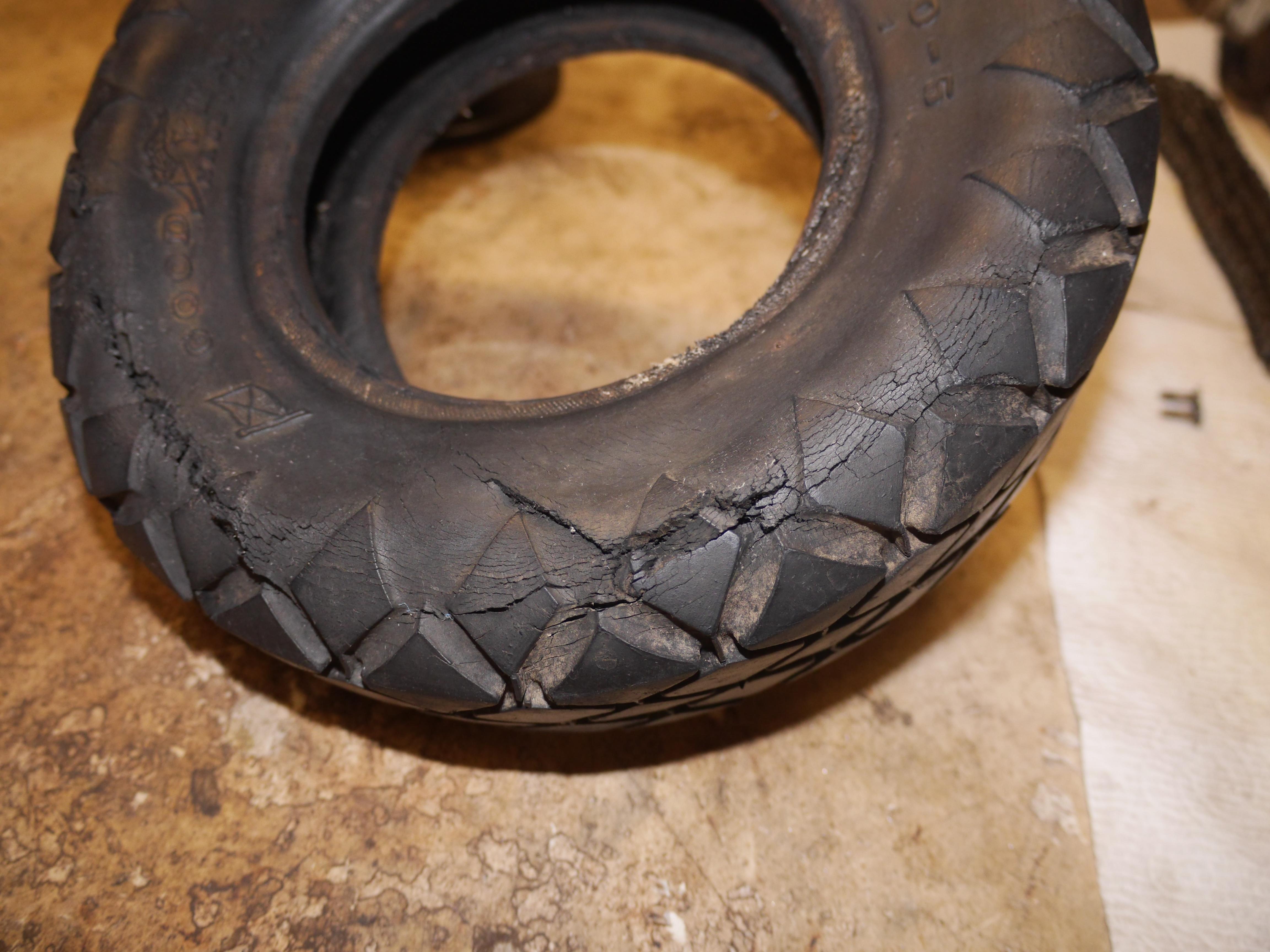
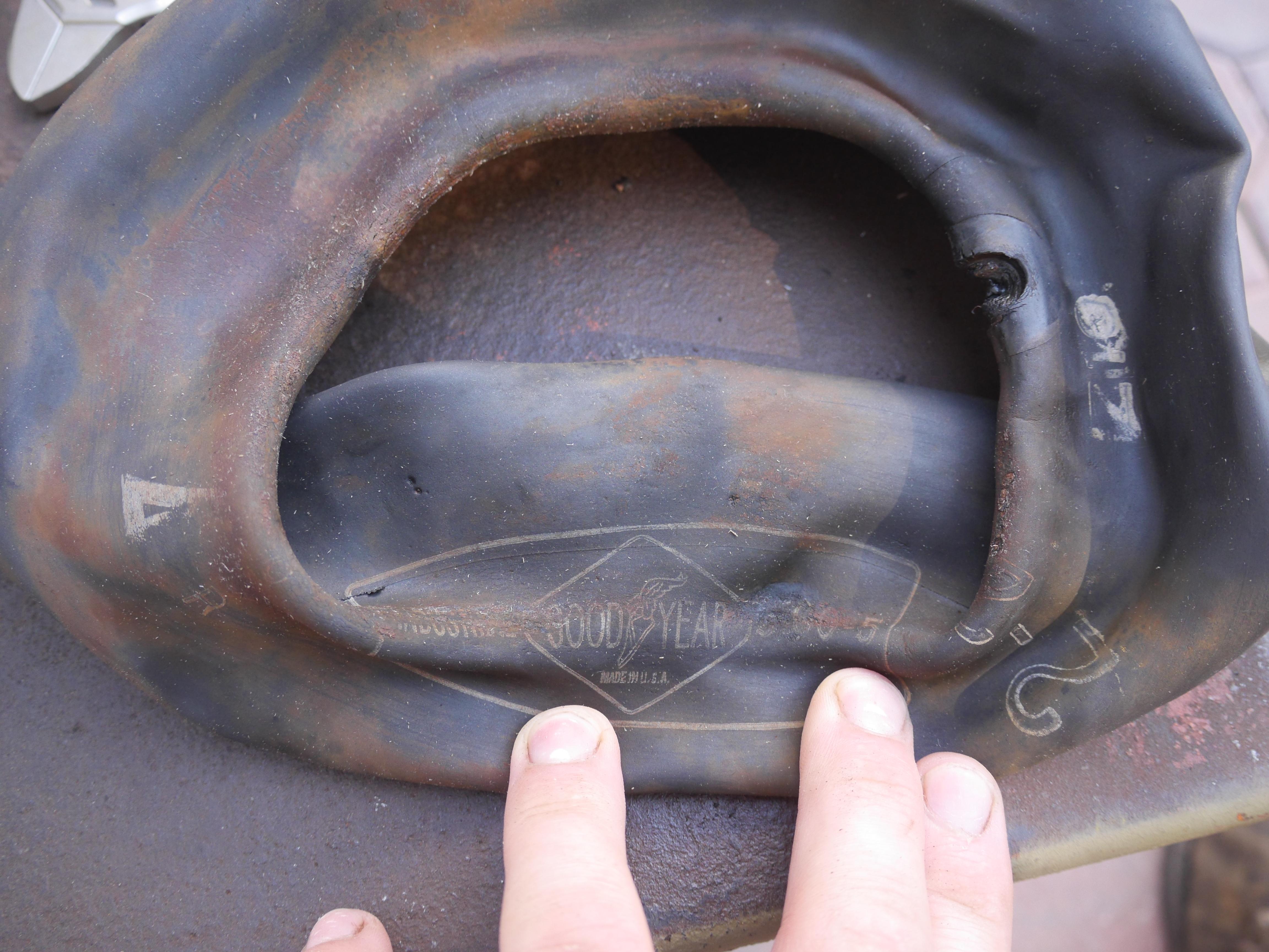
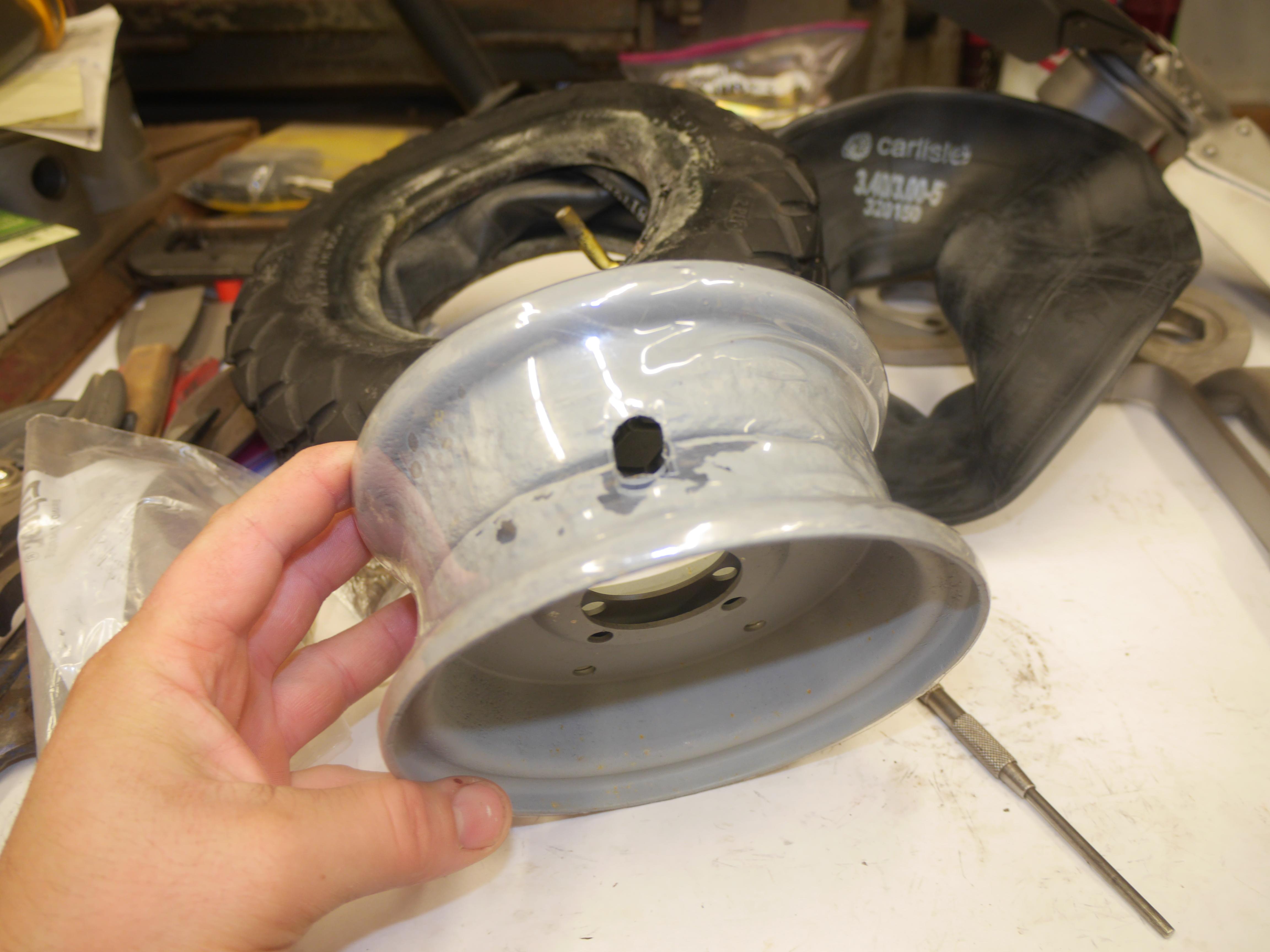
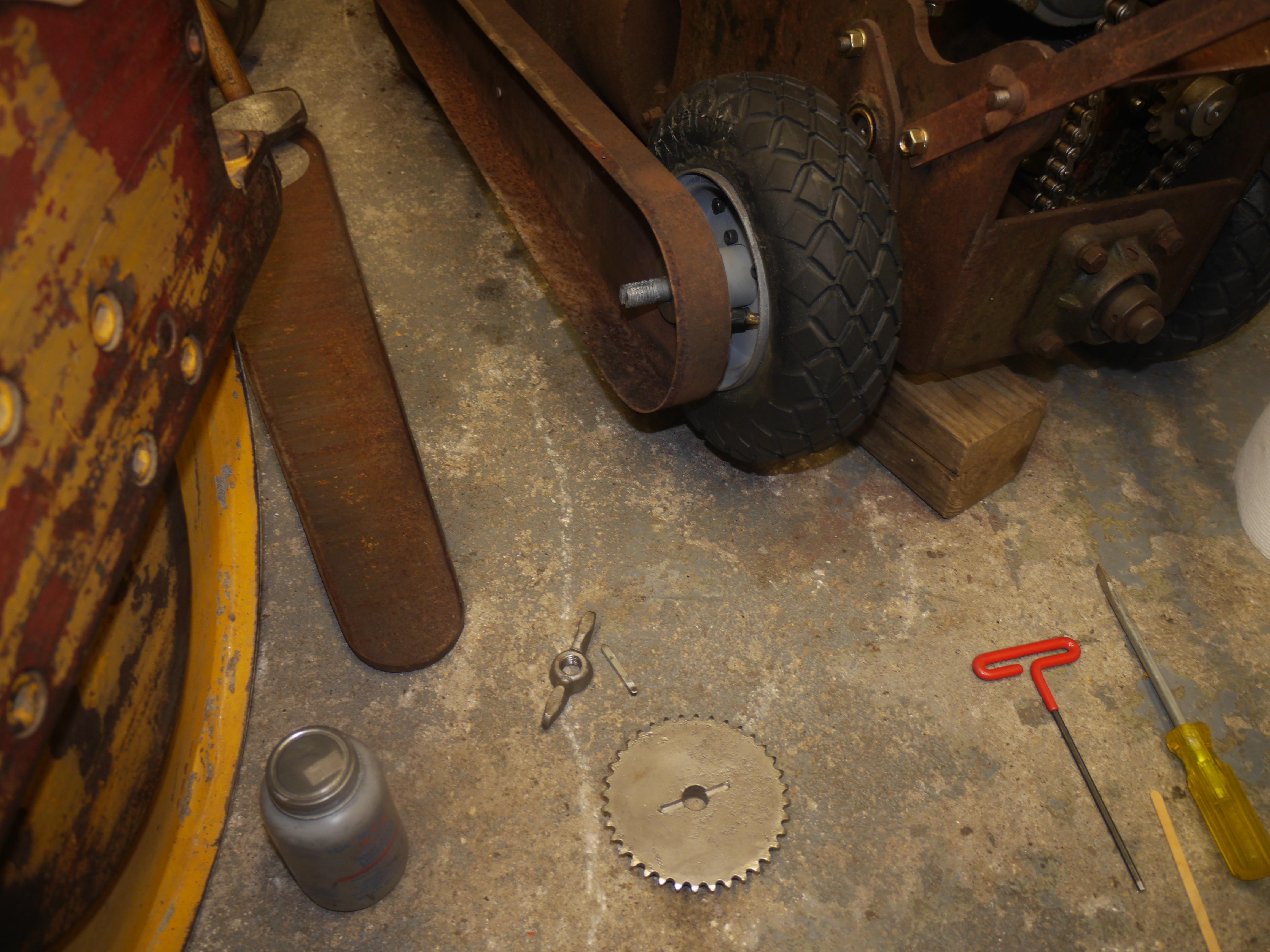
Throughout the whole process of rebuilding the engine, and repairing the fuel tank and carburetor, I had been dis-assembling the entire drive of this machine. I waited until now to speak about this procedure to keep the restoration log from jumping around too much. In mid-September I set out to remove the original tires so that I could see about replacing them. I know how hard it is to find 3.00-5 tires, as one of my other Maxim snow throwers also uses this obsolete tire size. It was no surprise that I could not find a replacement Goodyear branded tire, so I had to figure out what I could do to make this work again. As you can see the rims did not fare well over the years.
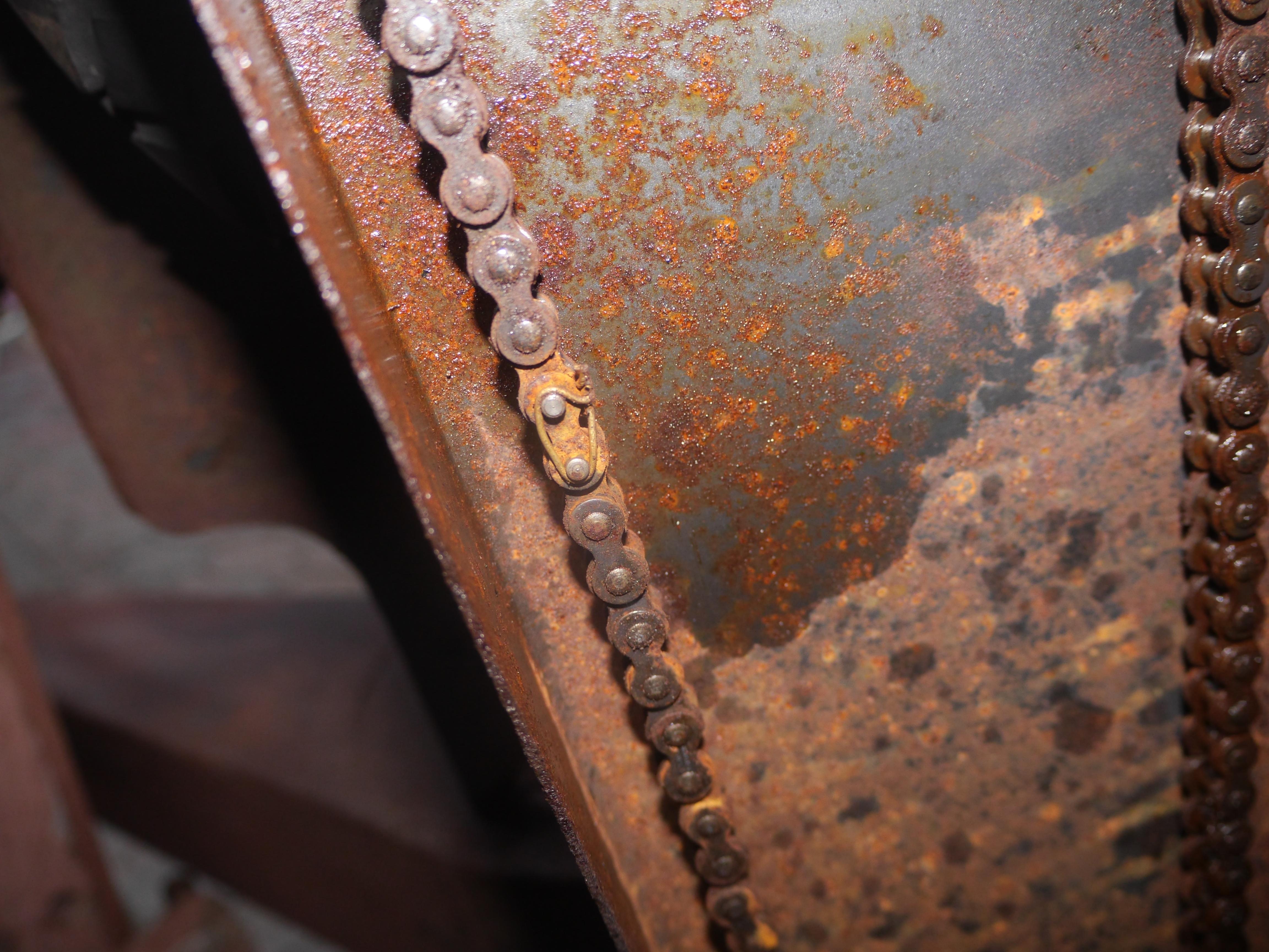
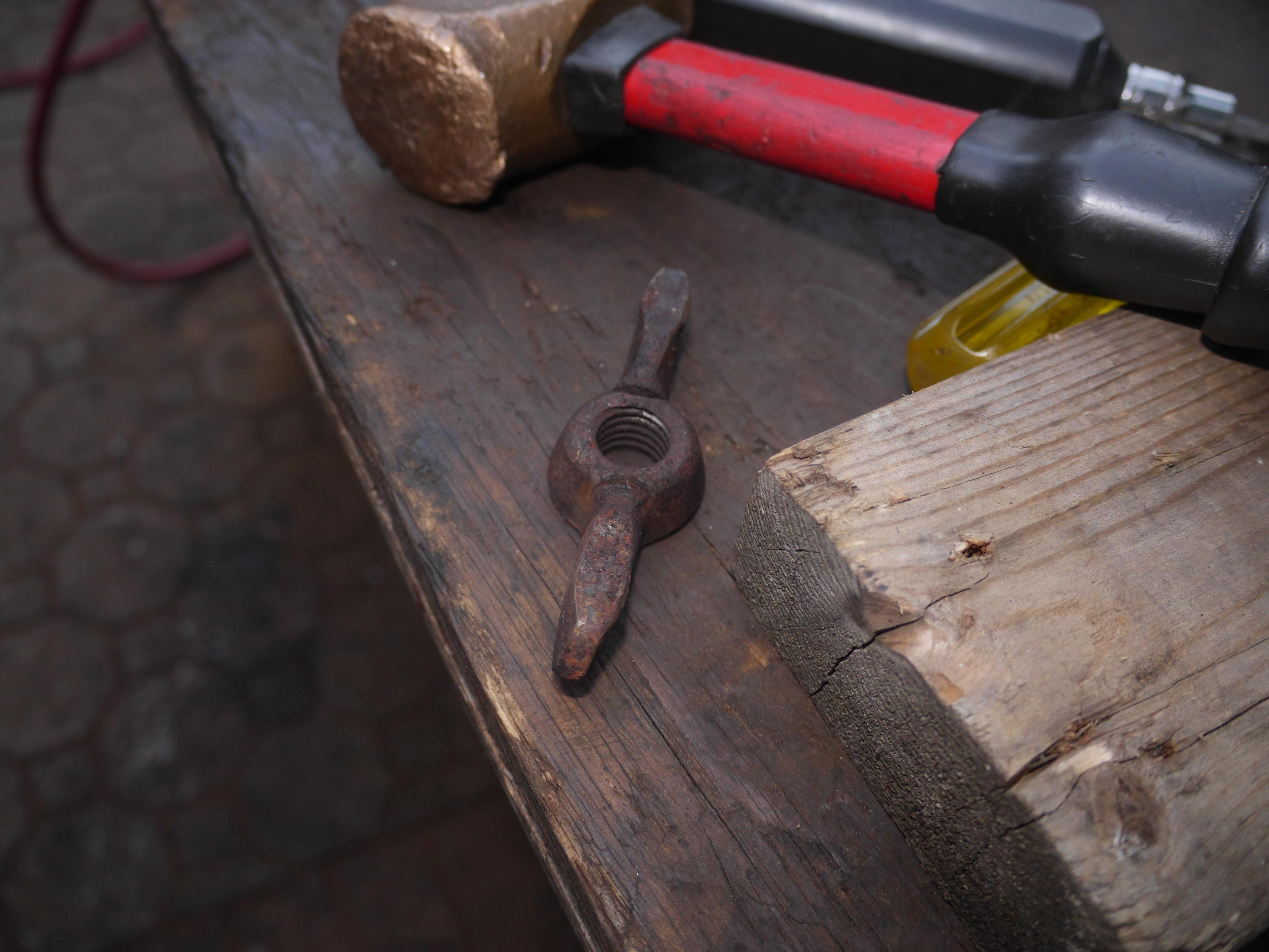
In order to remove the other tire, first the chain drive for the auger must be removed. I removed the perimeter screws, which to my surprise came out without too much trouble. Behind the inspection cover was an extremely rusty wingnut. I removed the entire chain cover and was surprised at how rusty everything was. Inside the chain cover I discovered that someone has been in there before. The original replaceable chain link must have broken and it was replaced with just a simple piece of tie wire.

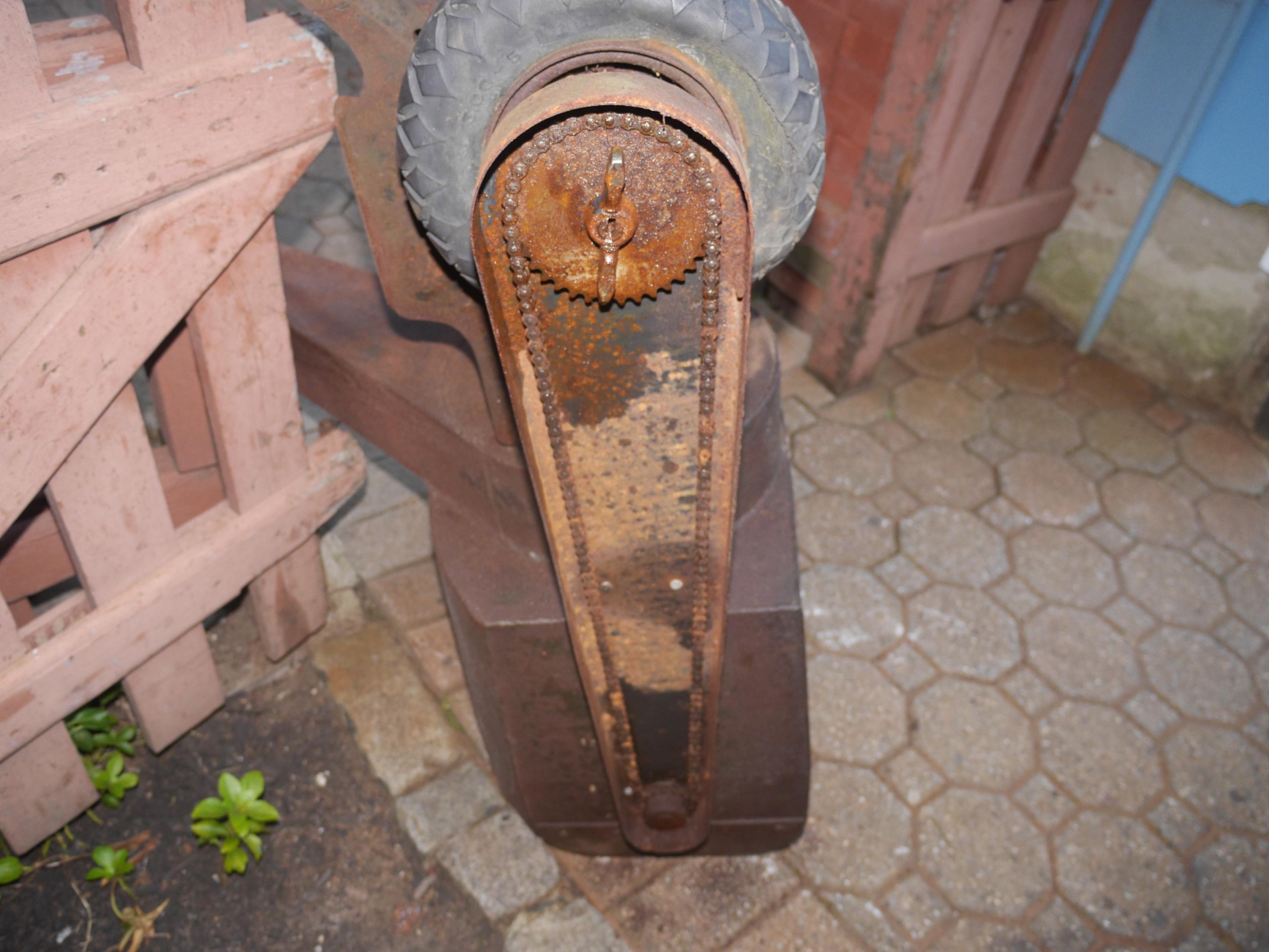
I was able to remove the chain without too much trouble, but the wingnut was a totally different story. There was enough visible threads to see that the end of the axle had normal threads cut into it. I sprayed the front and sides of the wingnut as much as possible, but it just would not come loose. With the aid of an acetylene torch I was finally able to remove the wingnut without damaging anything. Behind the wingnut was what appeared to be a long 1/4" key which locked the sprocket to the axle. I tried to push the key out of the way with several different punches, and it just would not move. I ended up threading the wingnut back on to prevent damaging the end of the axle with my three jaw puller.
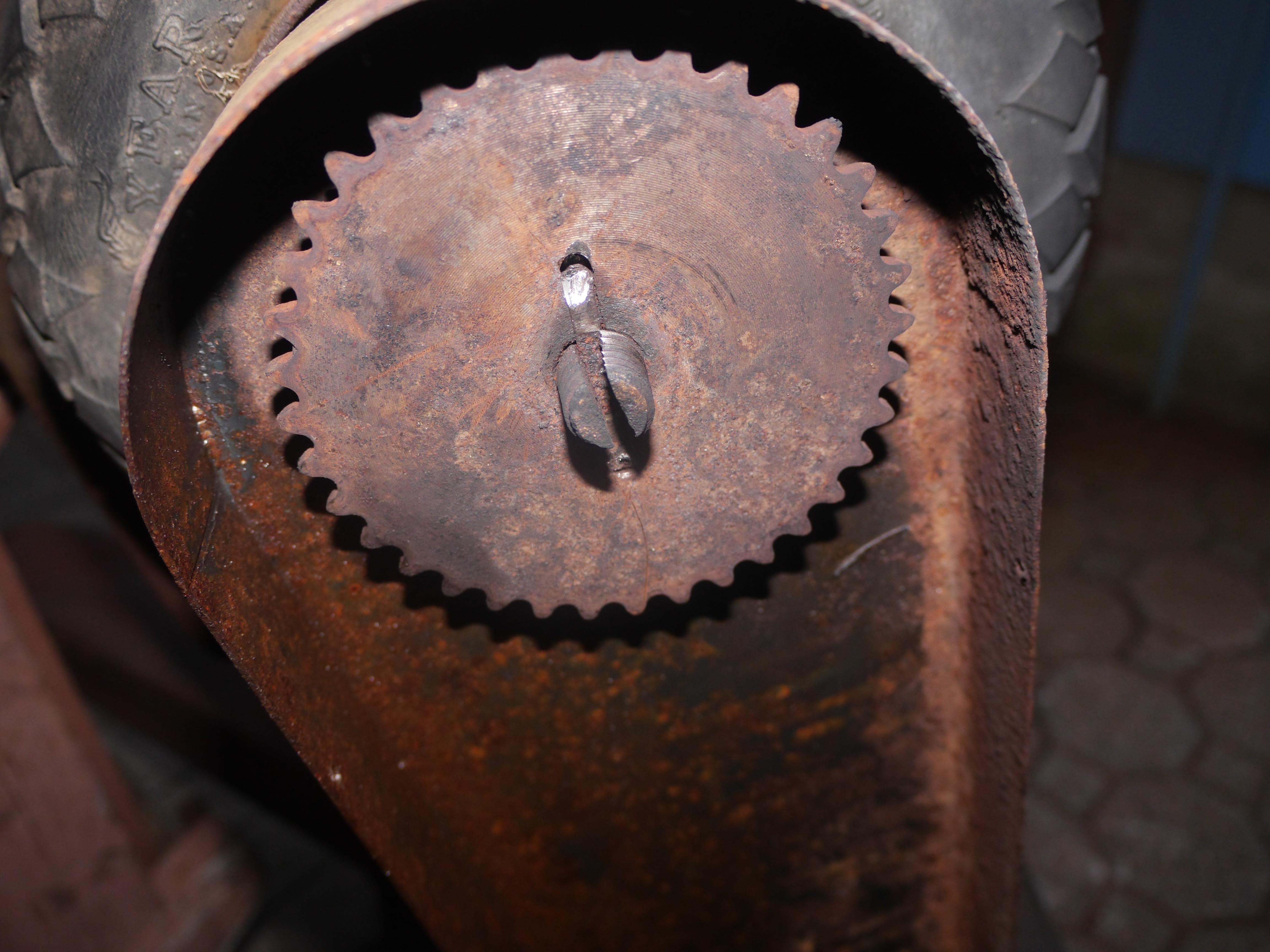
With the puller installed, I focused on heating the sprocket as much as possible so that I could pull the sprocket and the key off of the axle at once. Unfortunately the puller just could not get the sprocket to budge. I had to use a pickle fork and a puller at the same time to get the sprocket to budge. Instead of coming off the shaft, the shaft just sheared off behind the pulley! I could not believe how strong that rust bond was!
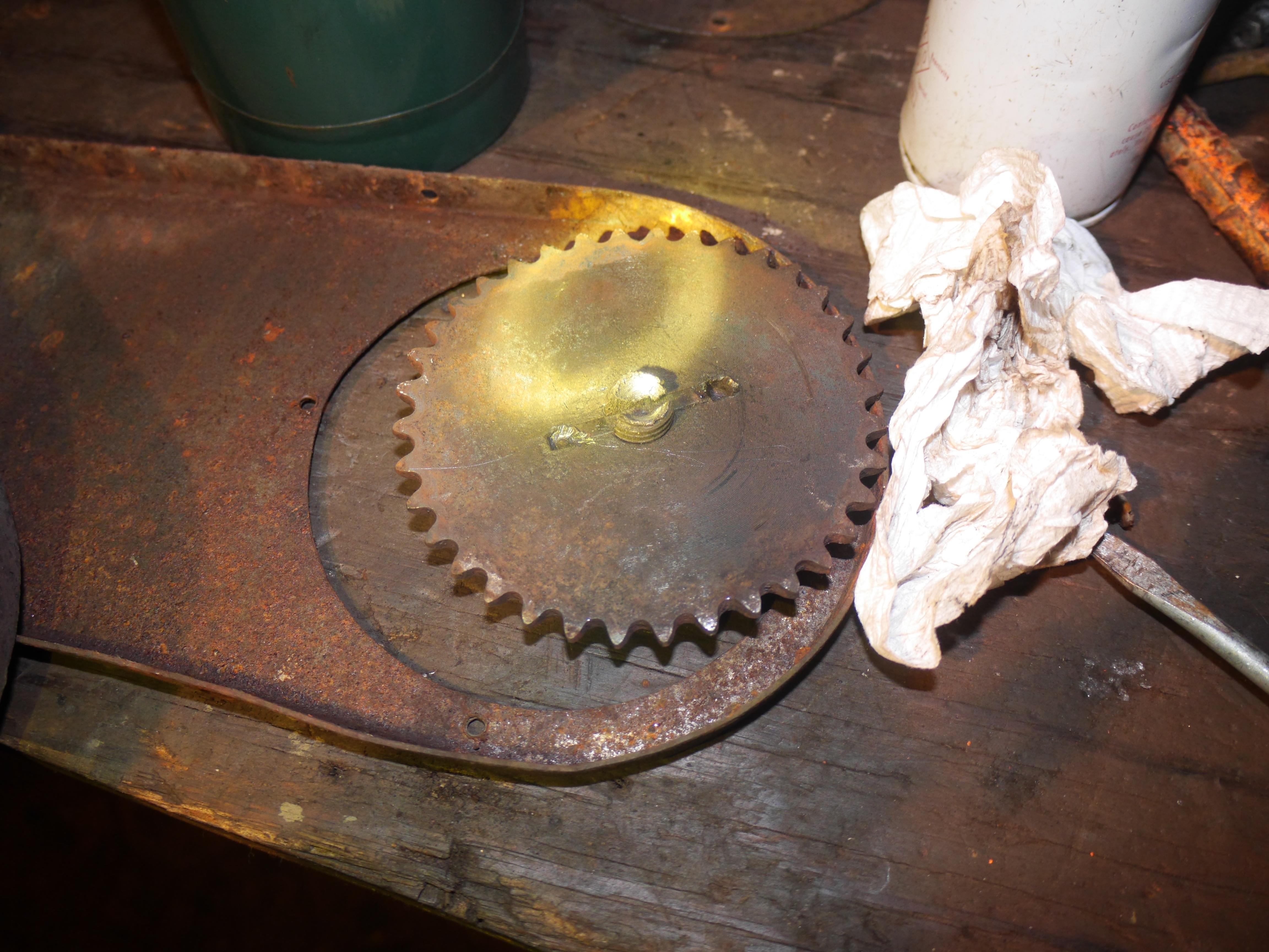
With the sprocket has removed, I was able to remove the remaining tire and rim. Thankfully it came off without too much trouble. In order to remove the axle for repairs. I removed the set screws which held the driven gear to the axle. It was quite a process to remove the gear from the axle, as there was a lot of rust on the shaft that had to be cleaned up first. Once the rust was removed, I was able to drive the axle out of the driven gear.
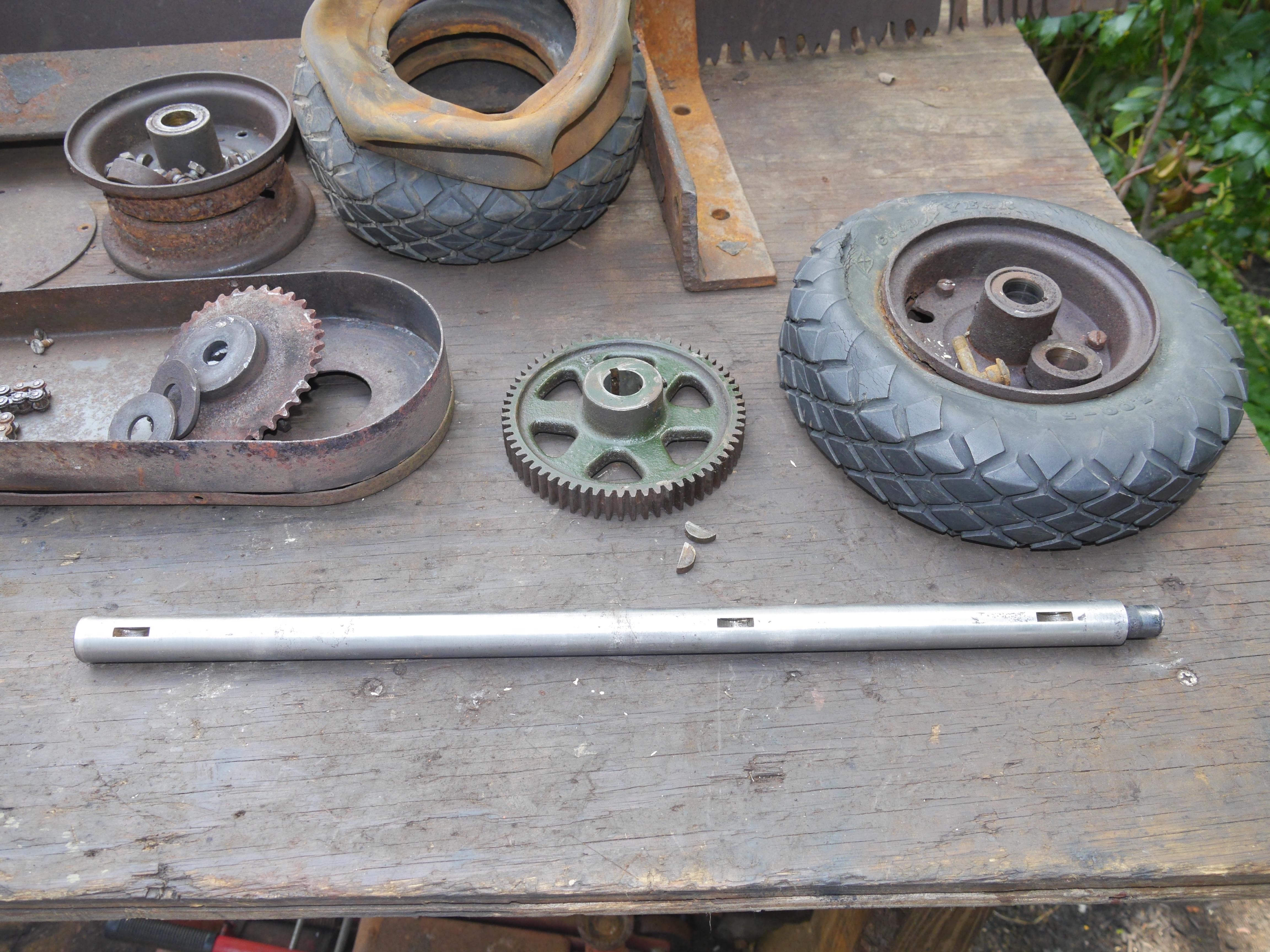
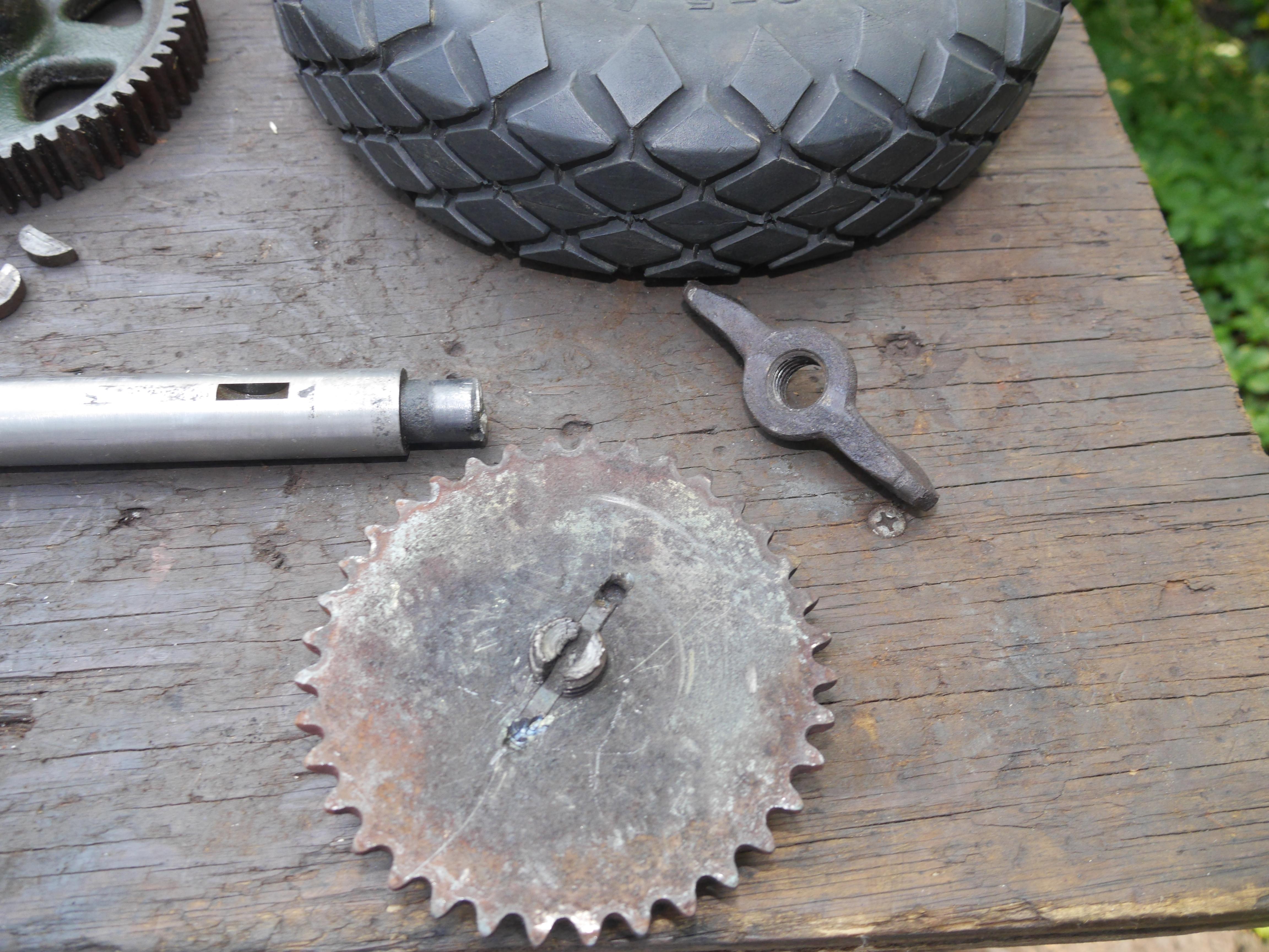
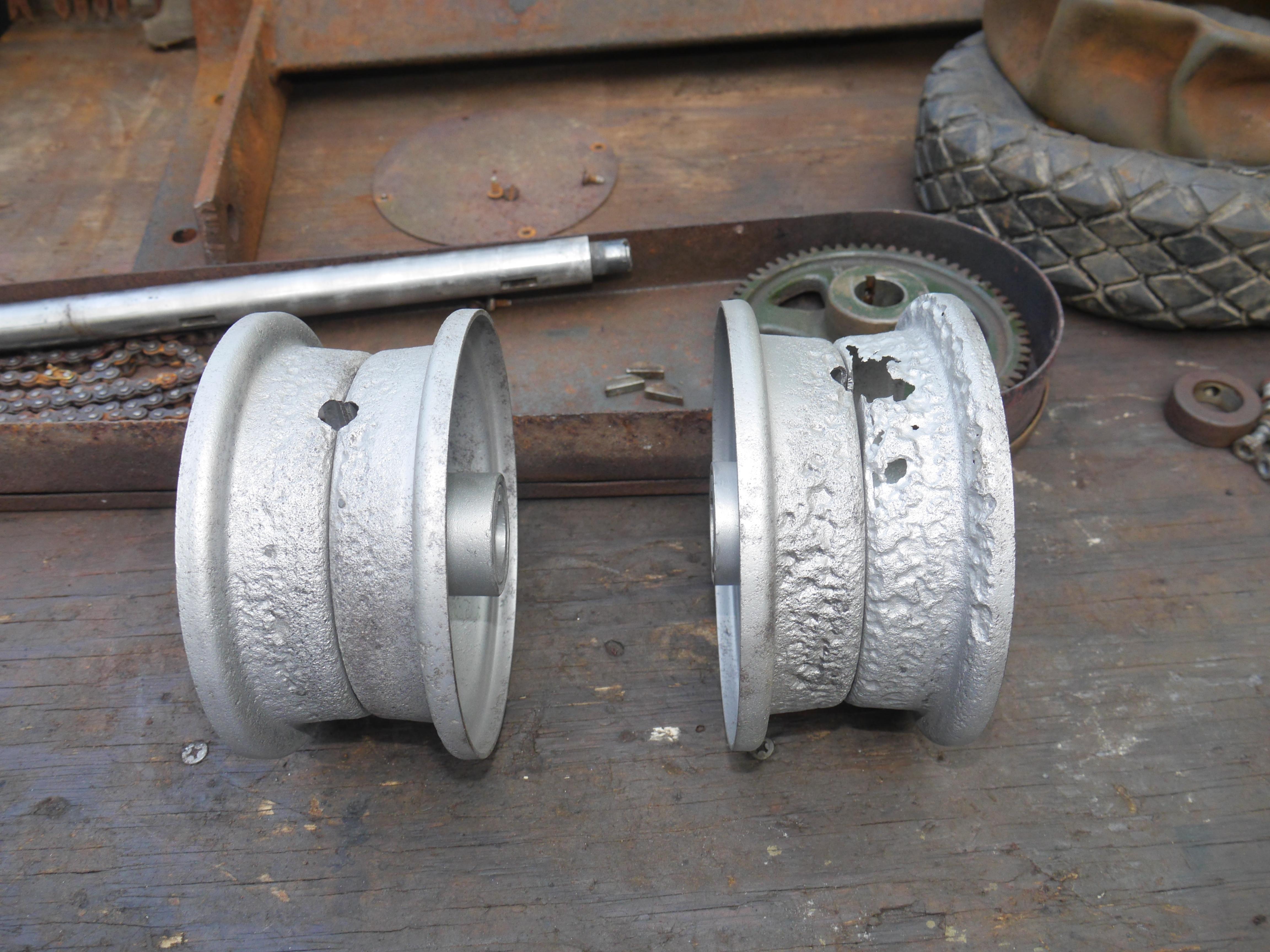
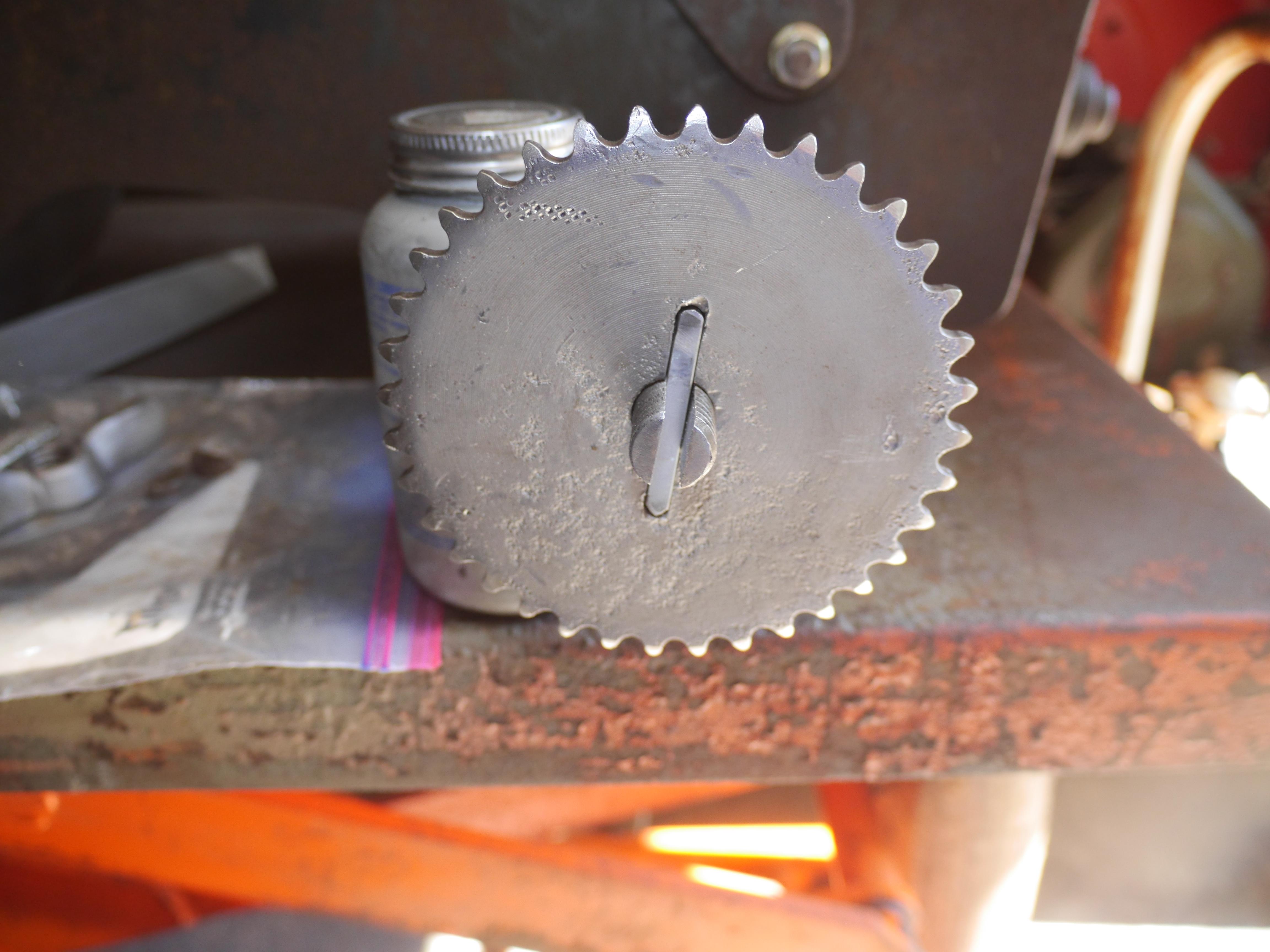
Finally both of the tires and rims were off! I disassembled the three piece rims and media blasted them to see what kind of shape they were in. I was almost sorry I sandblasted them. What a mess those rims were! In the last picture I drove the stuck 1/4" key out of the drive sprocket for the auger. Notice how bent the key is, that is a testament to how stuck the key was even with the opportunity to drive it out directly from the rear of the sprocket.
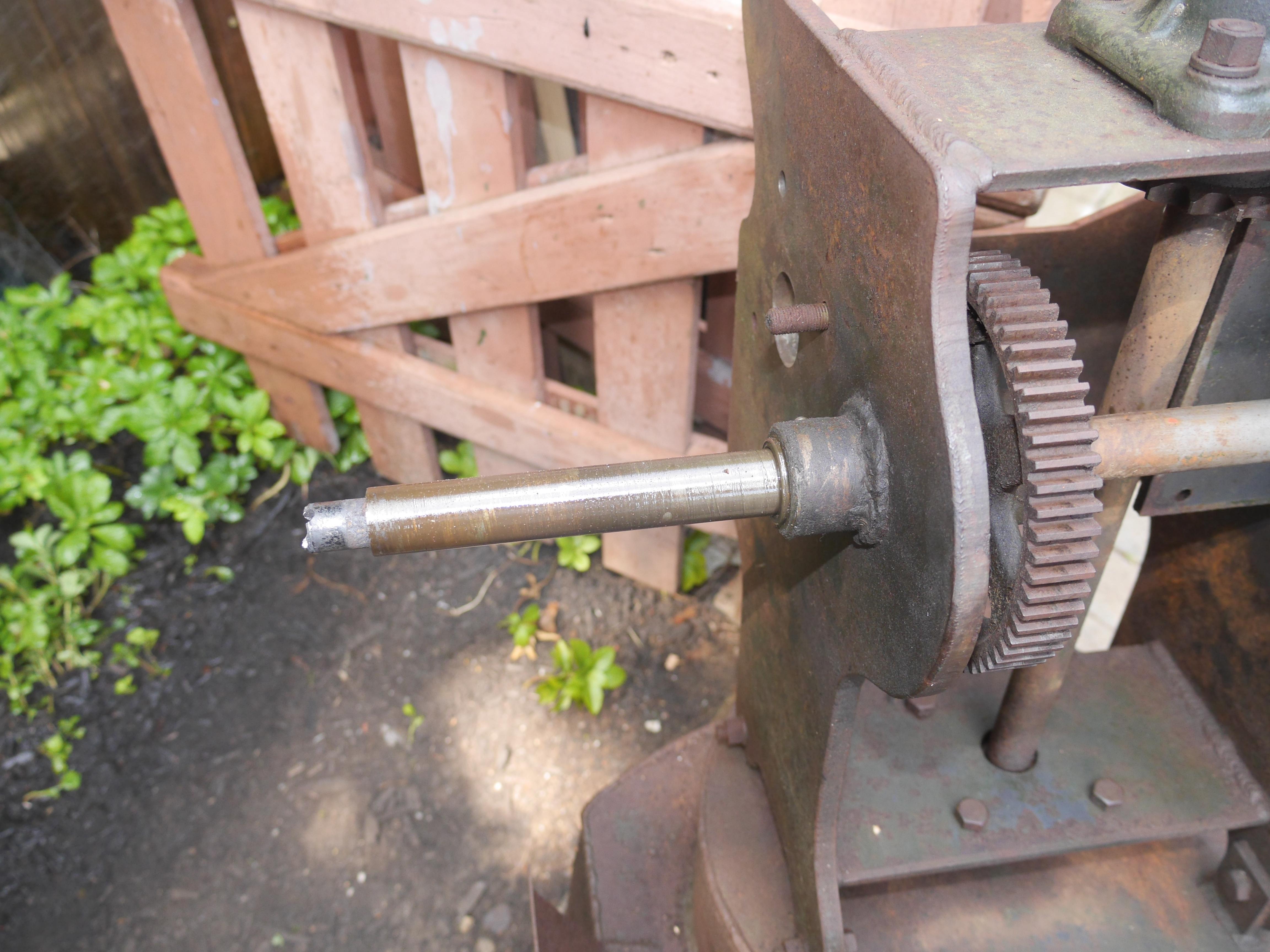
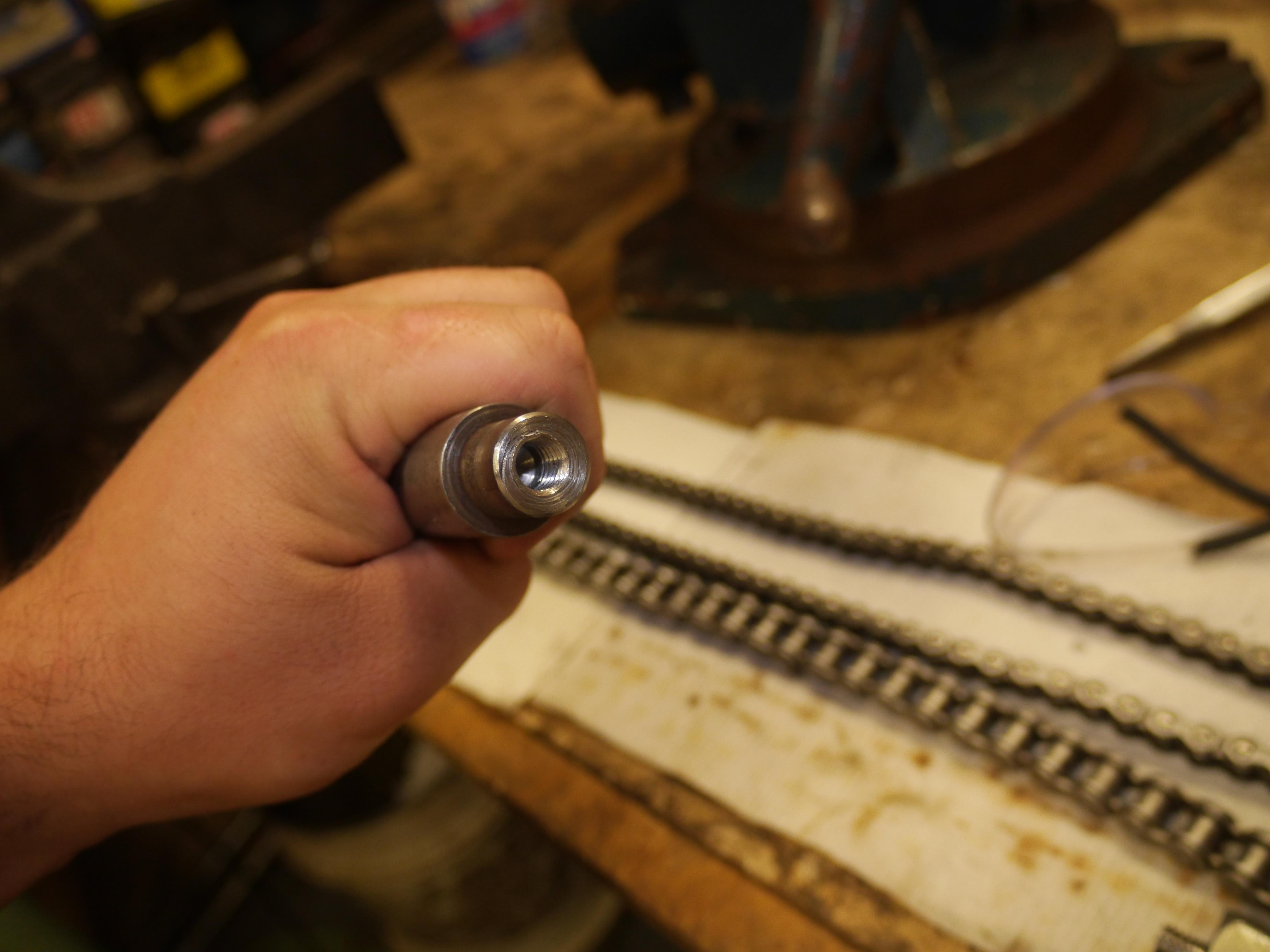
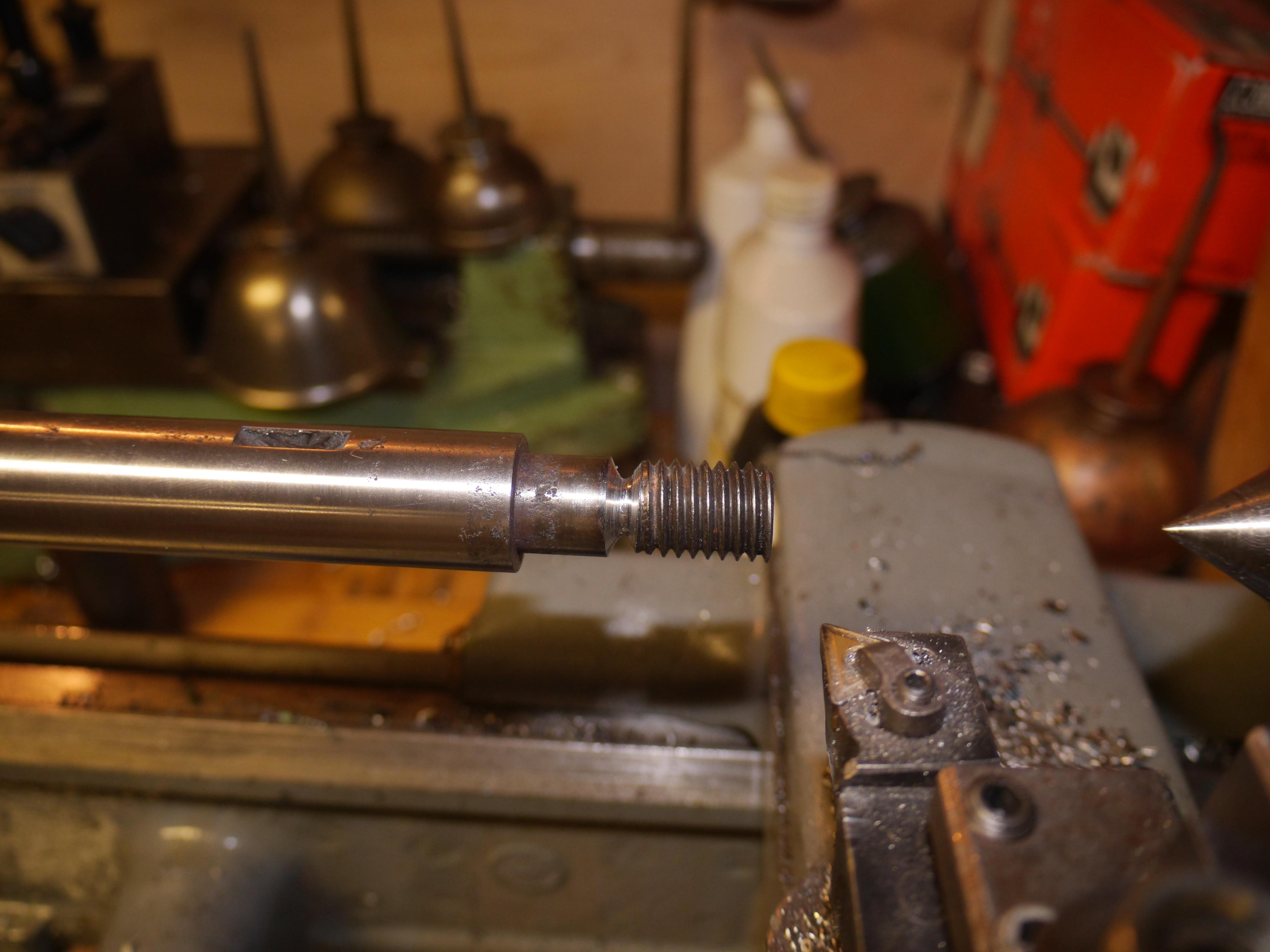
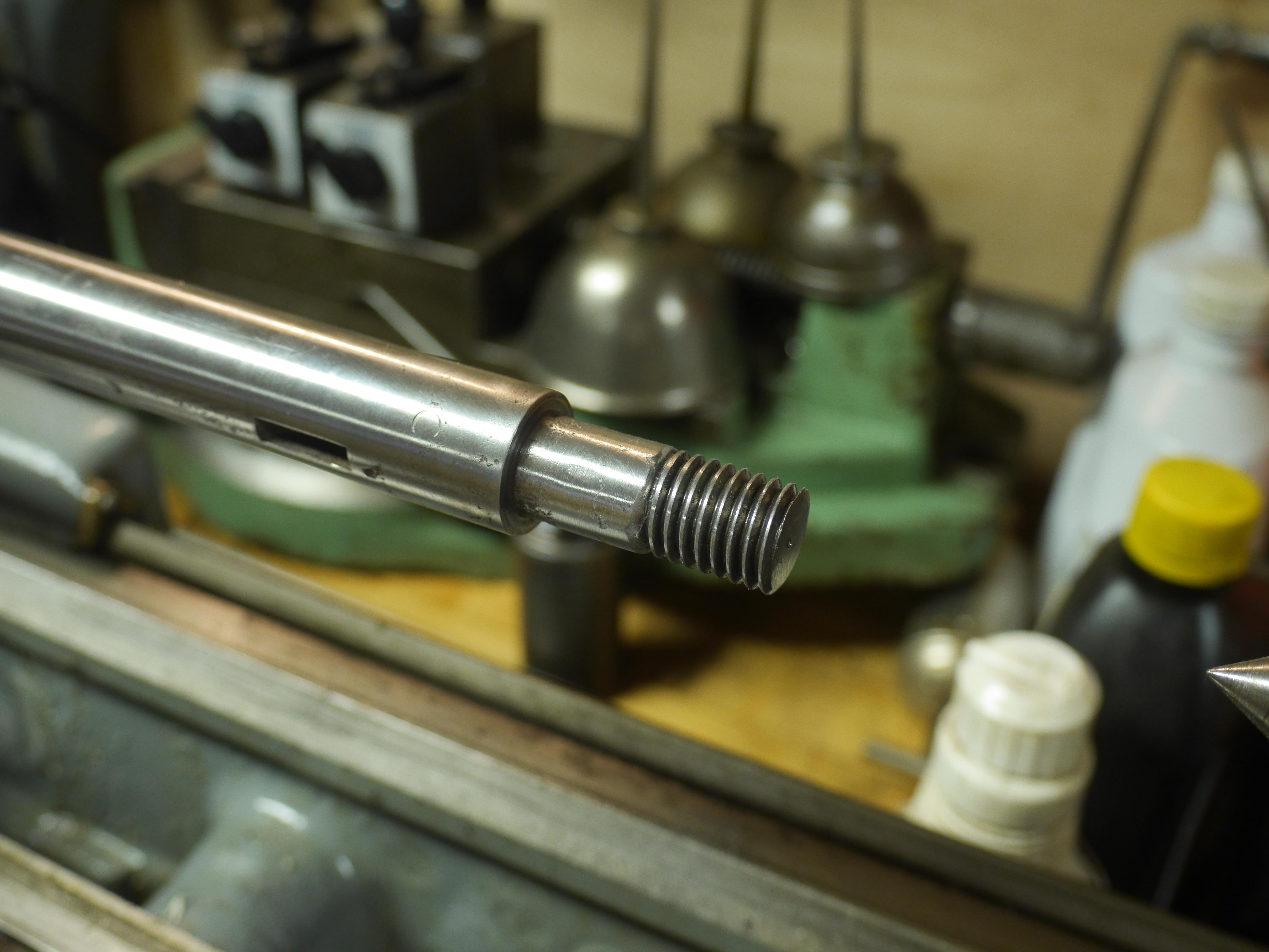
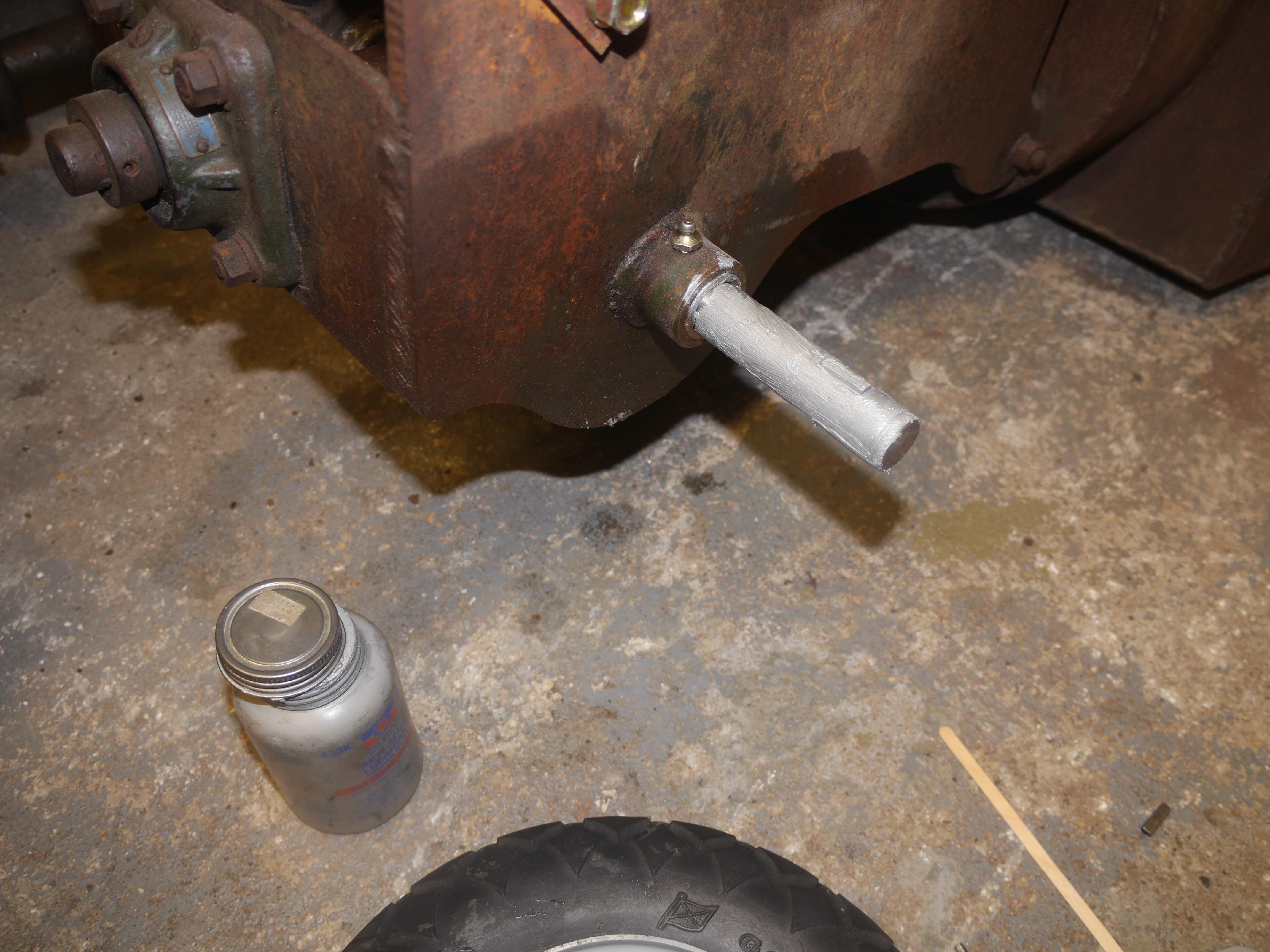
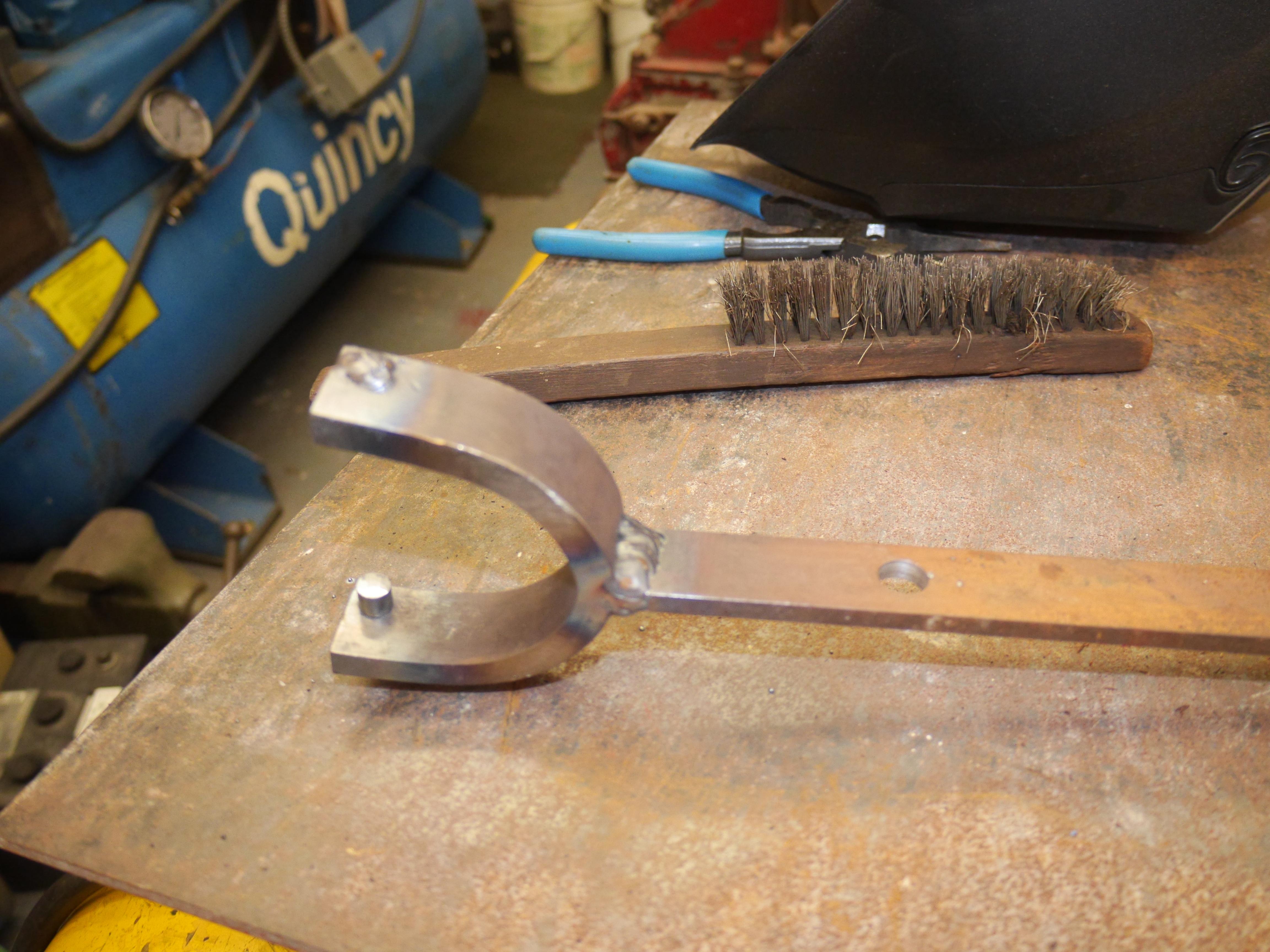
I basically had just two options to repair the axle; 1) make a new one from scratch, or 2) repair the broken off end. I decided to try and fix the original axle before attempting to make a new one. Thankfully the wingnut had a standard 5/8-11 thread, so I grabbed a spare 5/8-11 bolt and began modifying it to suit my needs. I started out by turning the head of the bolt down until it matched the solid web of th ebolt. Then I turned the solid section of the bolt down so that I could cut 3/8-16" threads into the "head" end of the bolt. I drilled the center of the old axle out and tapped it to accept the stub shaft I made.
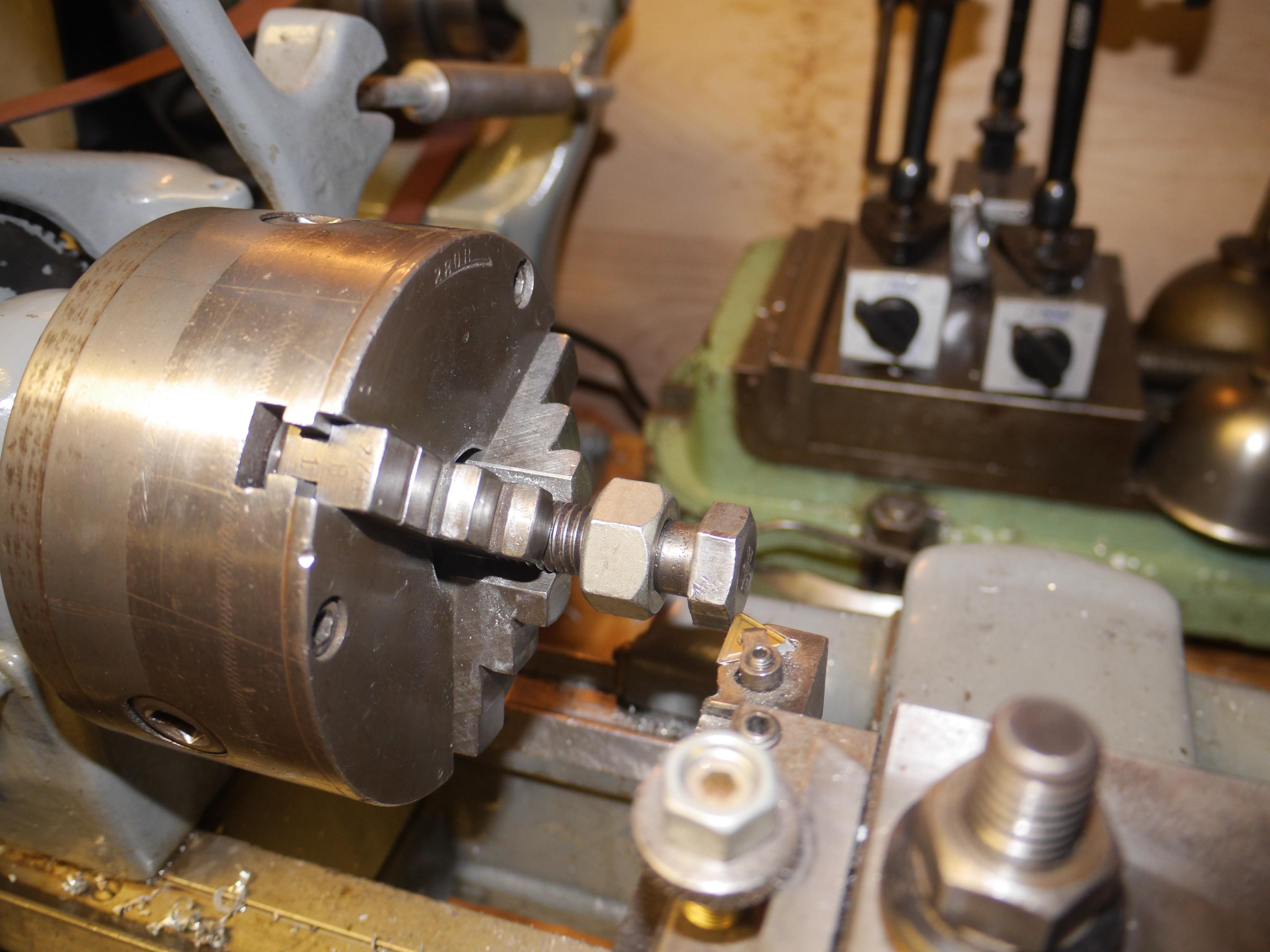
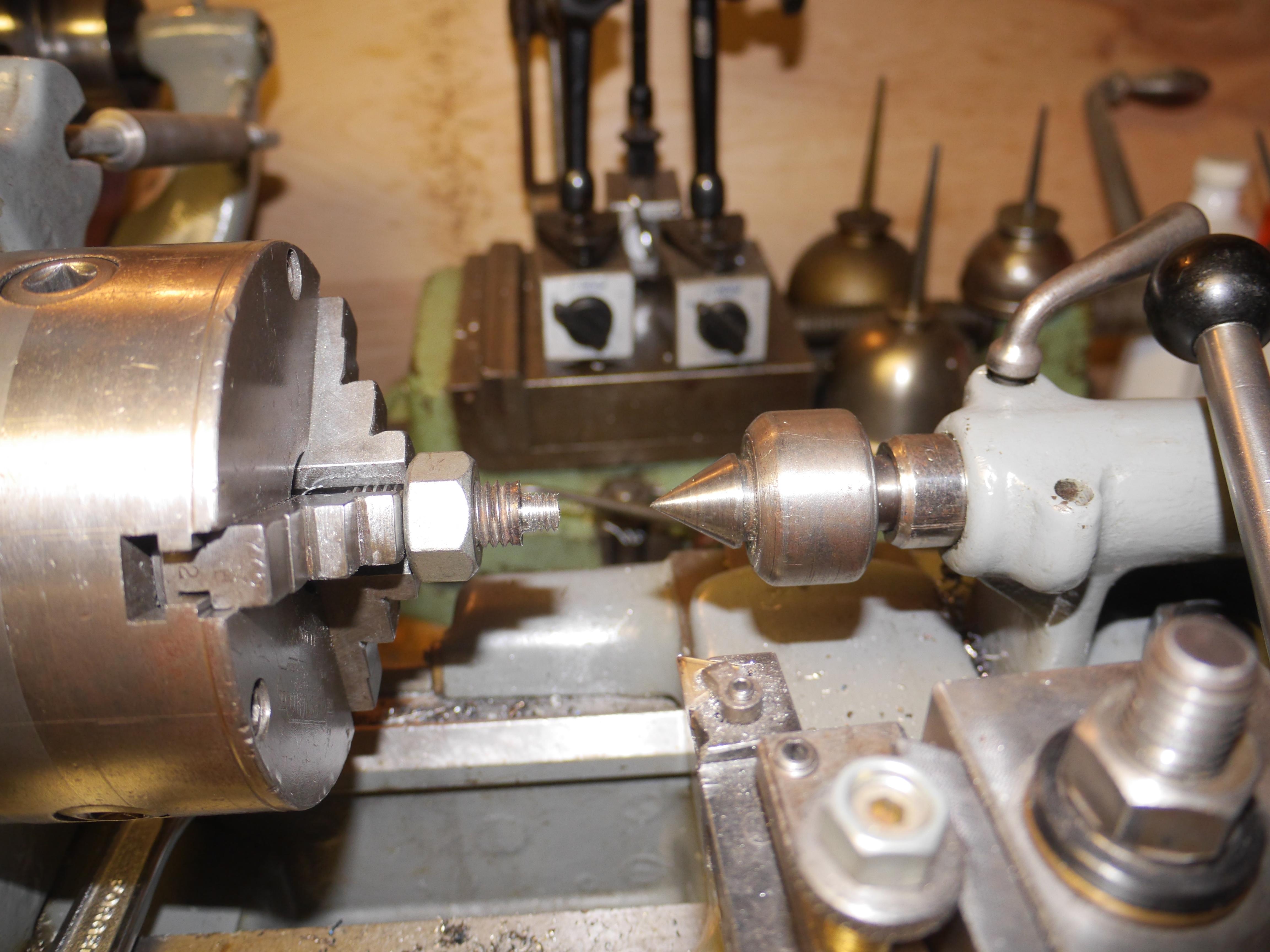

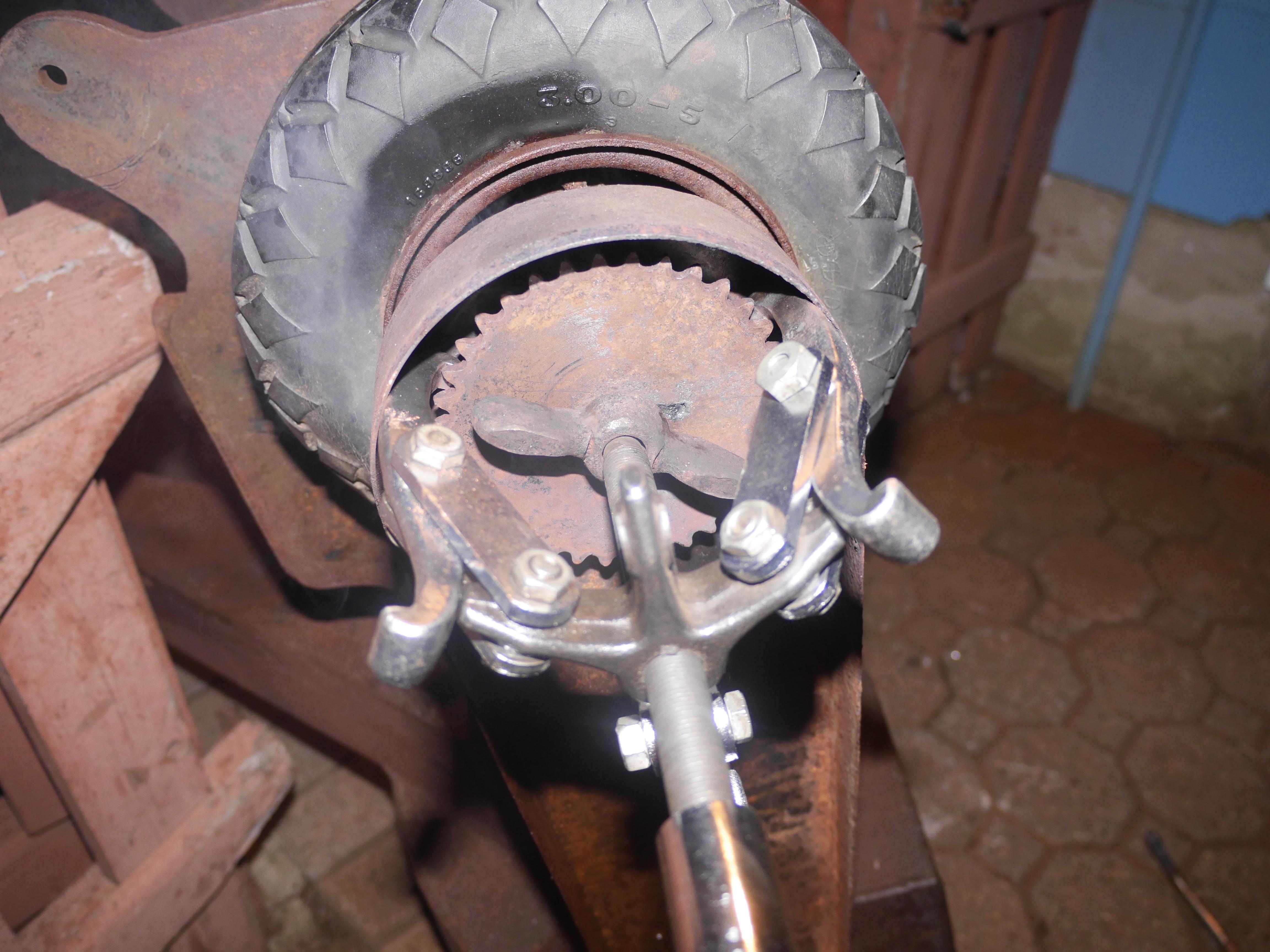
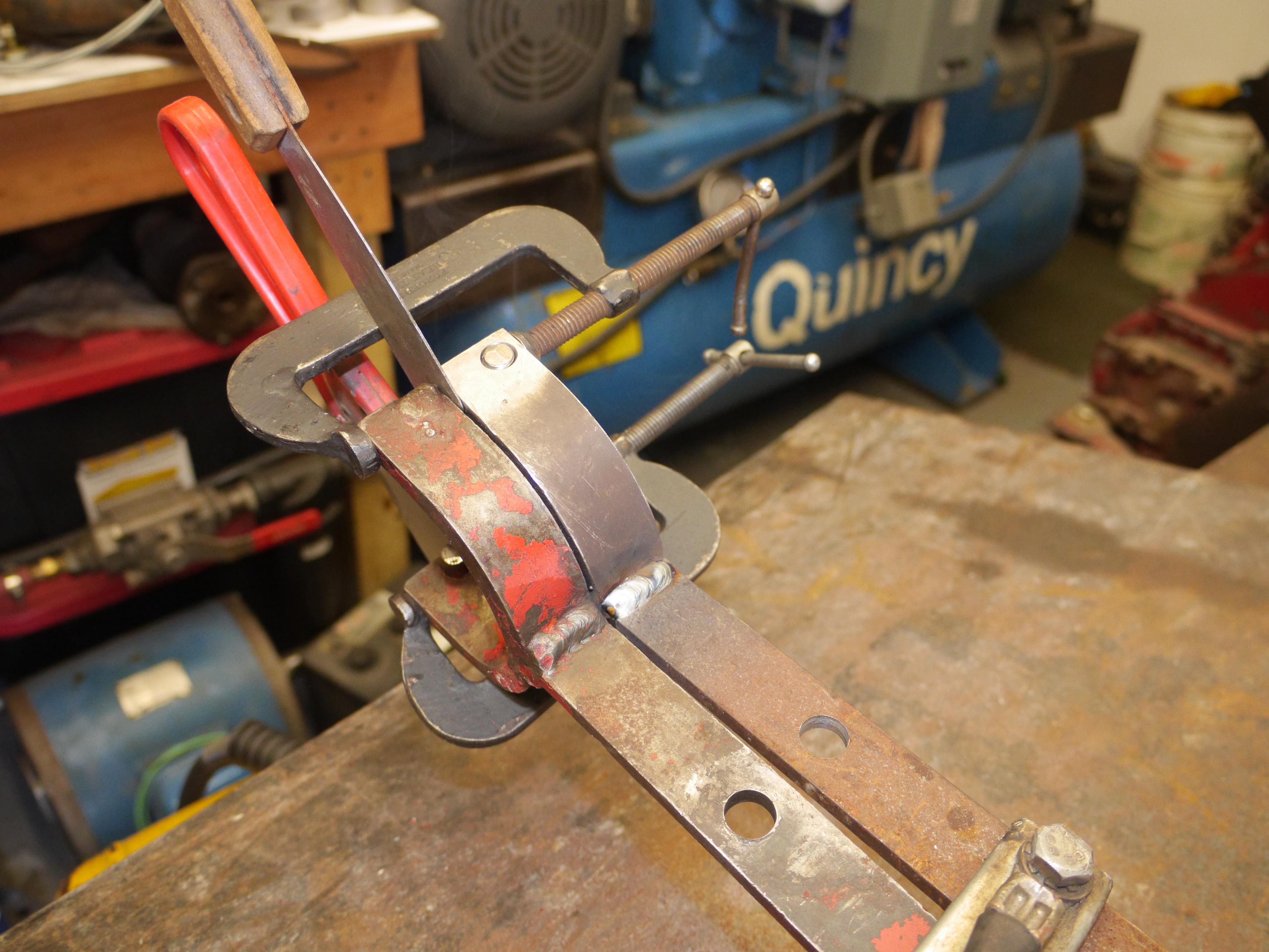
Once threaded together, I used a chamfering tool to make a nice wide vee in the bolt and the original axle for weld to take up. After welding the threaded stub shaft to the original axle, I turned the weld down and test fit the sprocket and wing nut.
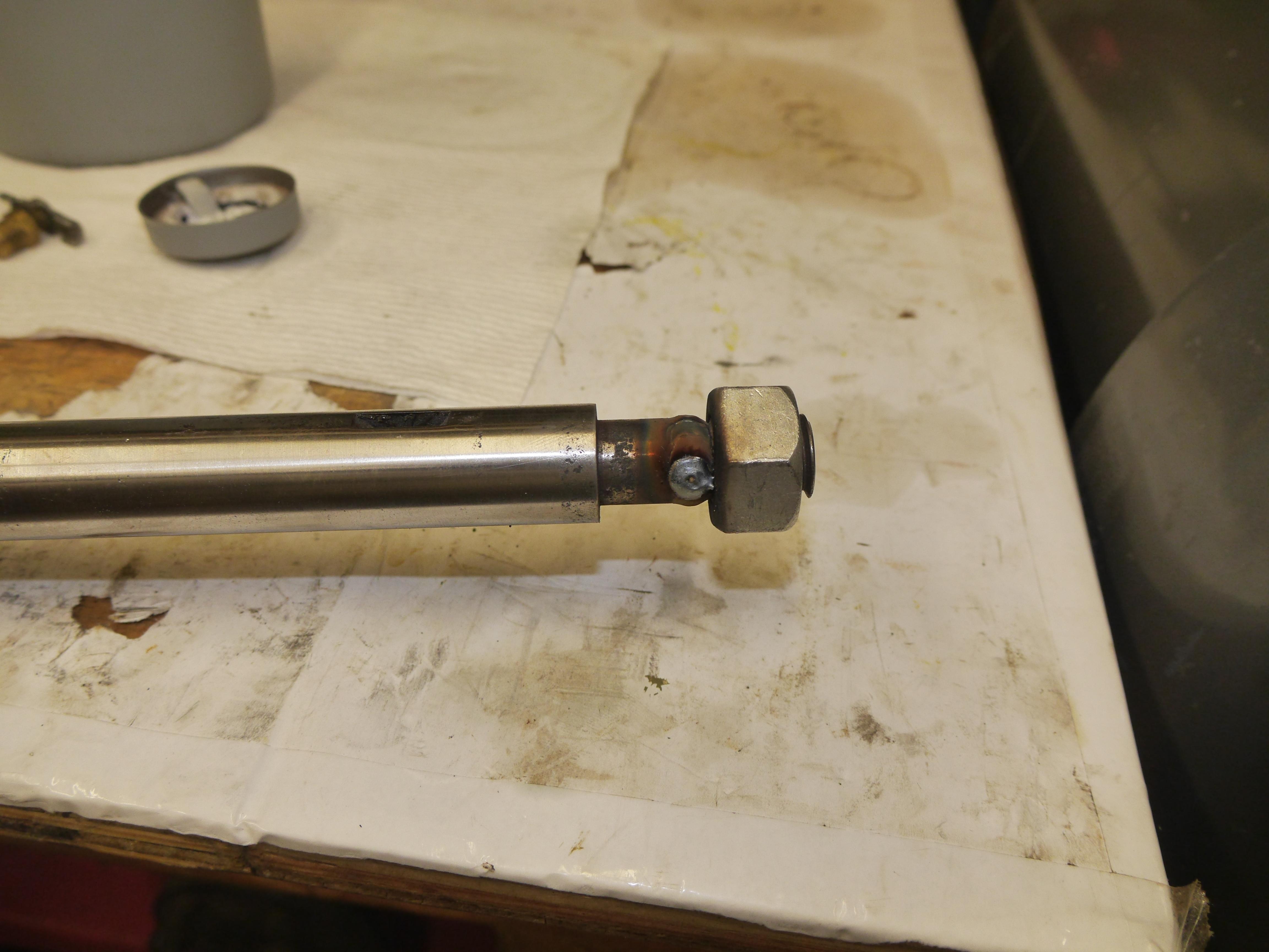

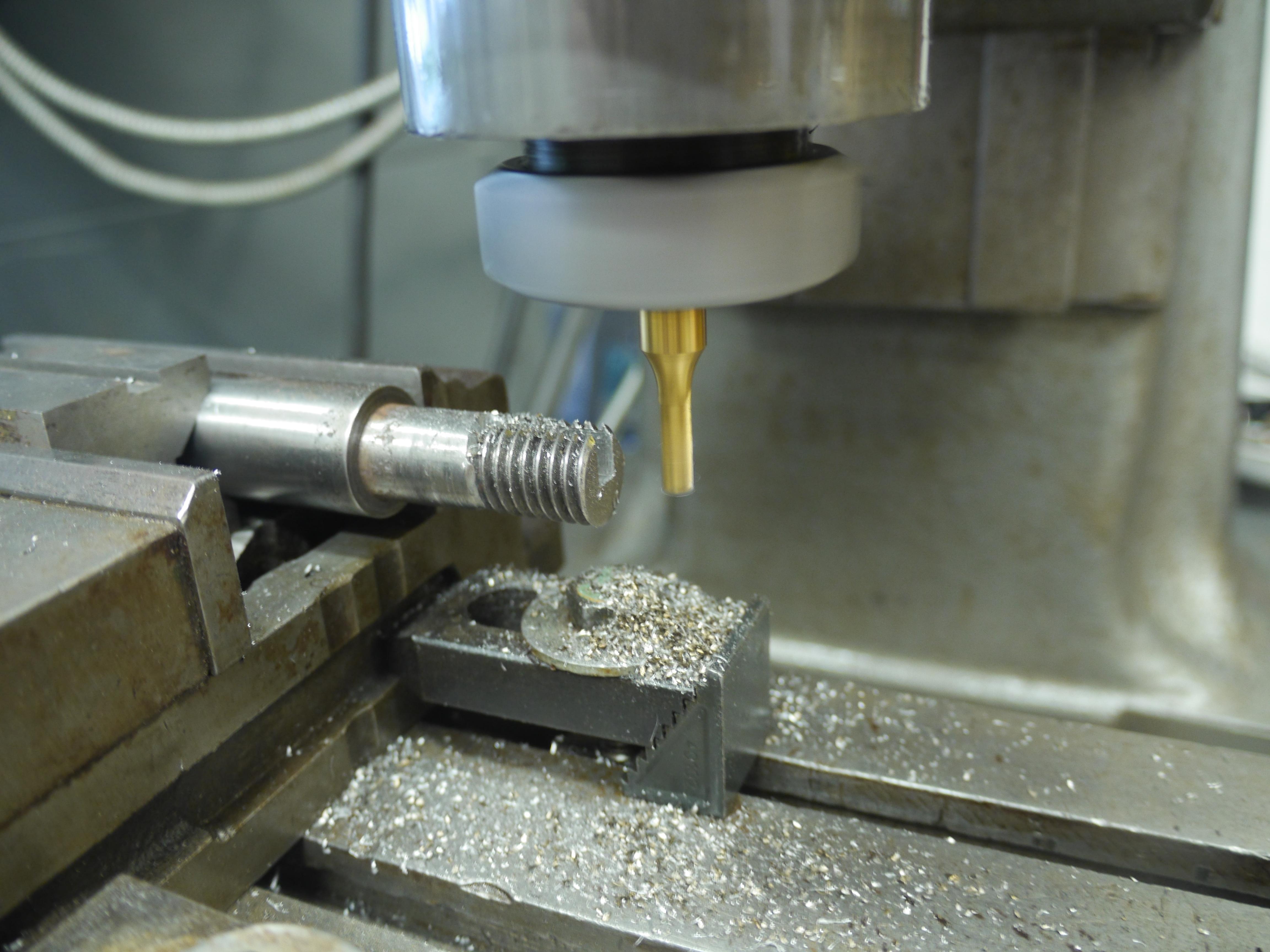
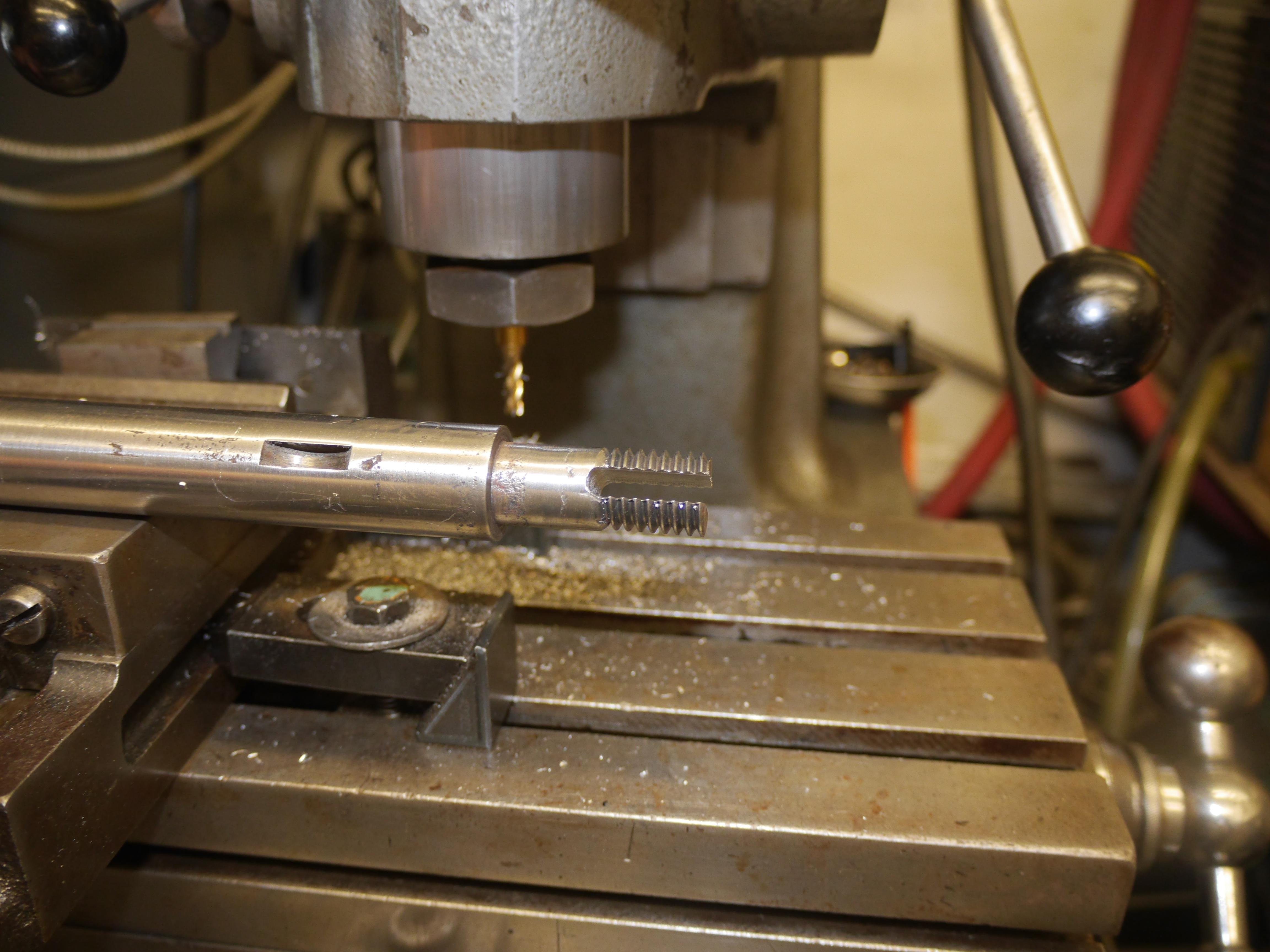
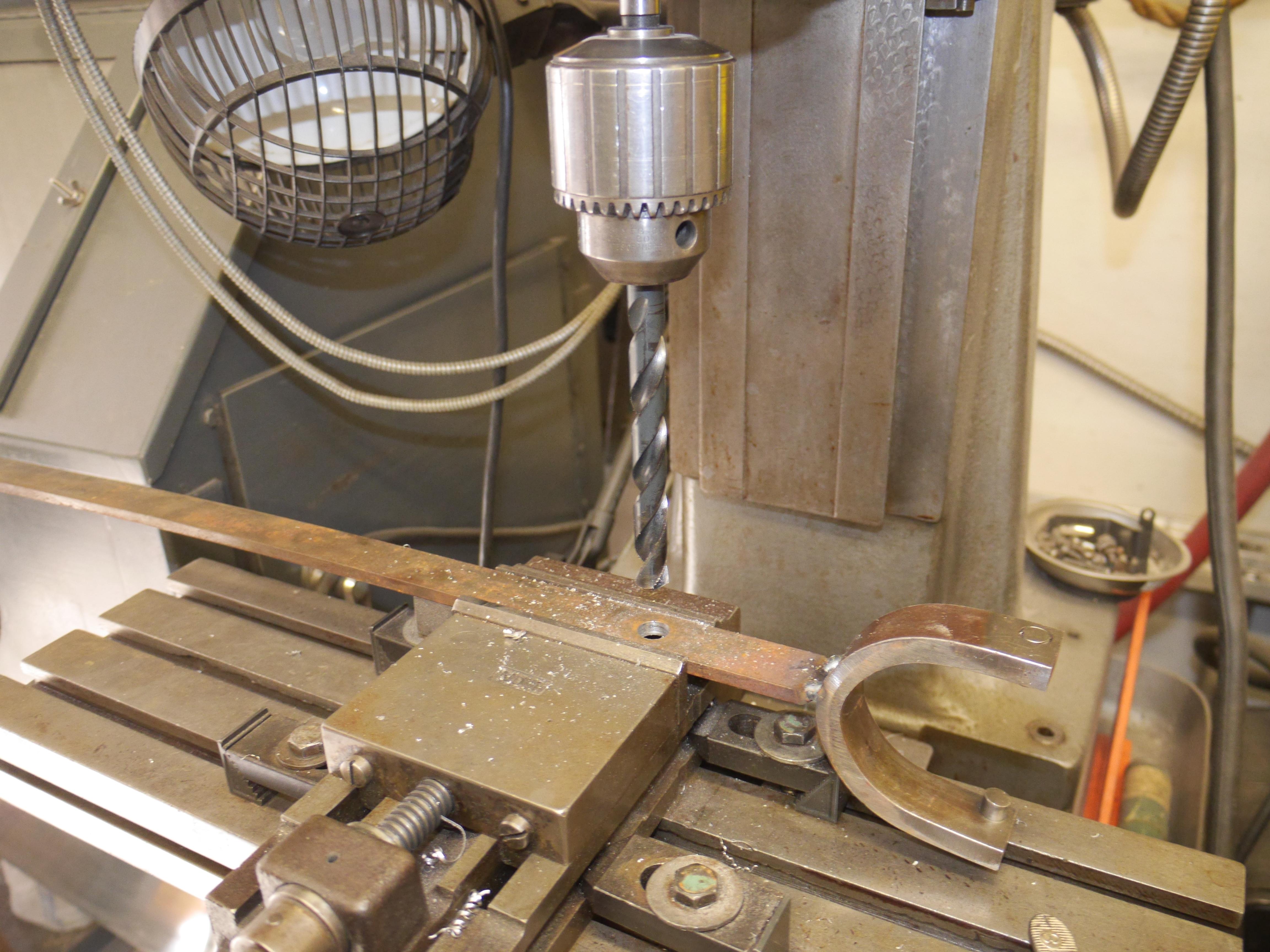
Before I could call the axle repaired, I had to machine a groove down the center of the bolt to lock the sprocket in place. I set up the axle in my jog borer and used a center finder to find the center of the shaft. Using a 1/4" endmill I was able to make a groove right down the center of the axle just like the original. The result was perfect, even the sprocket and new key worked out perfectly.

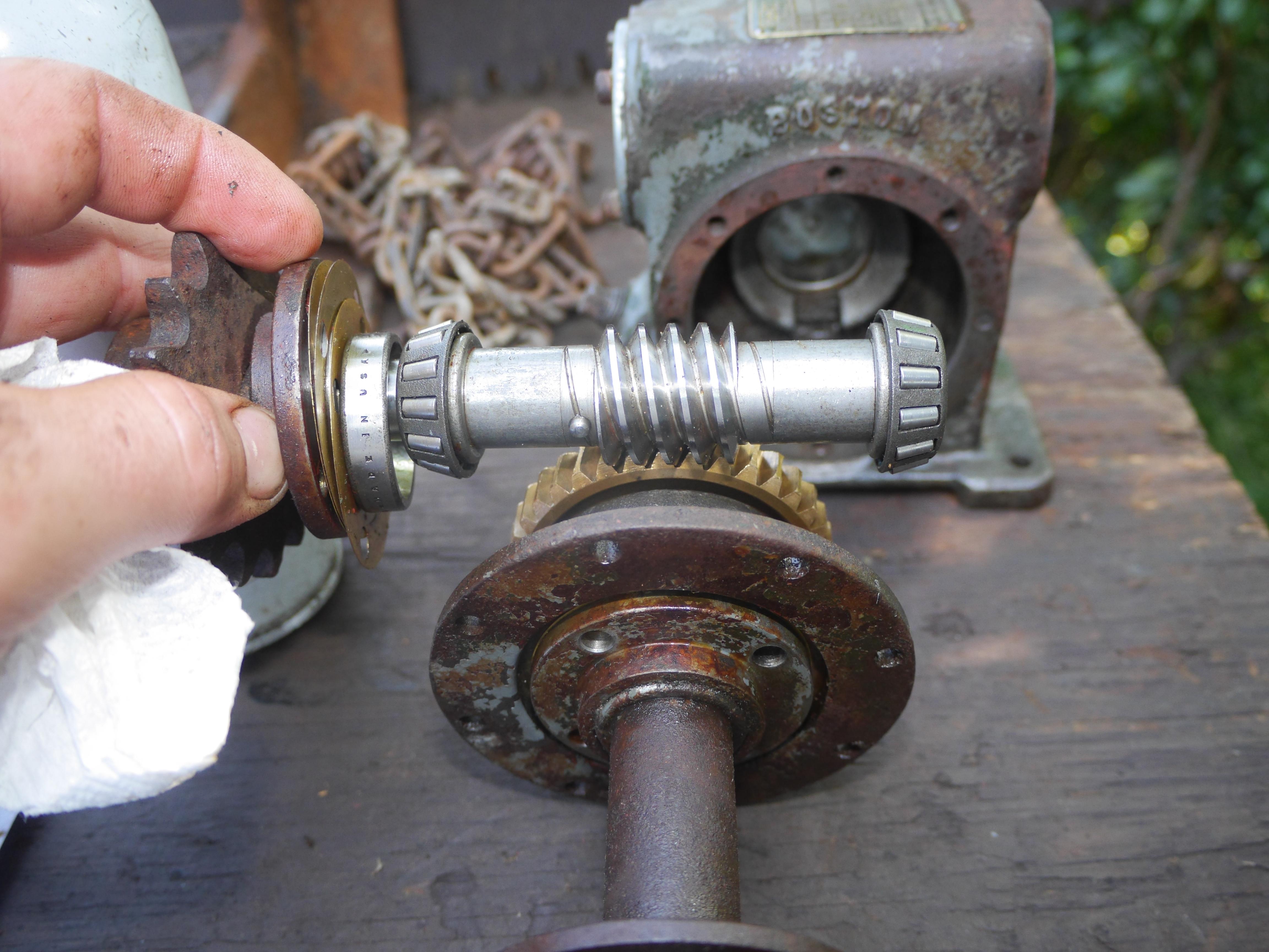
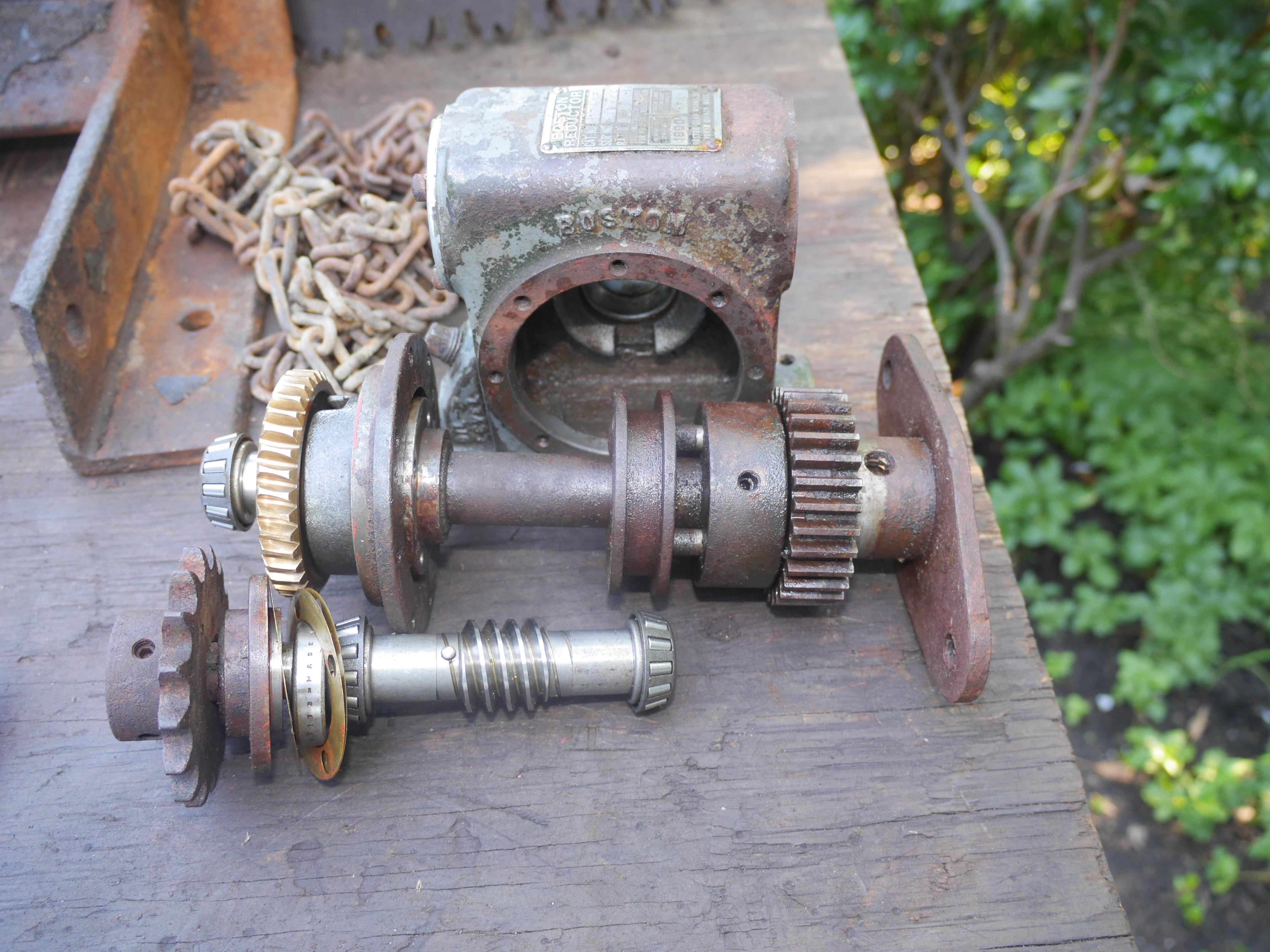
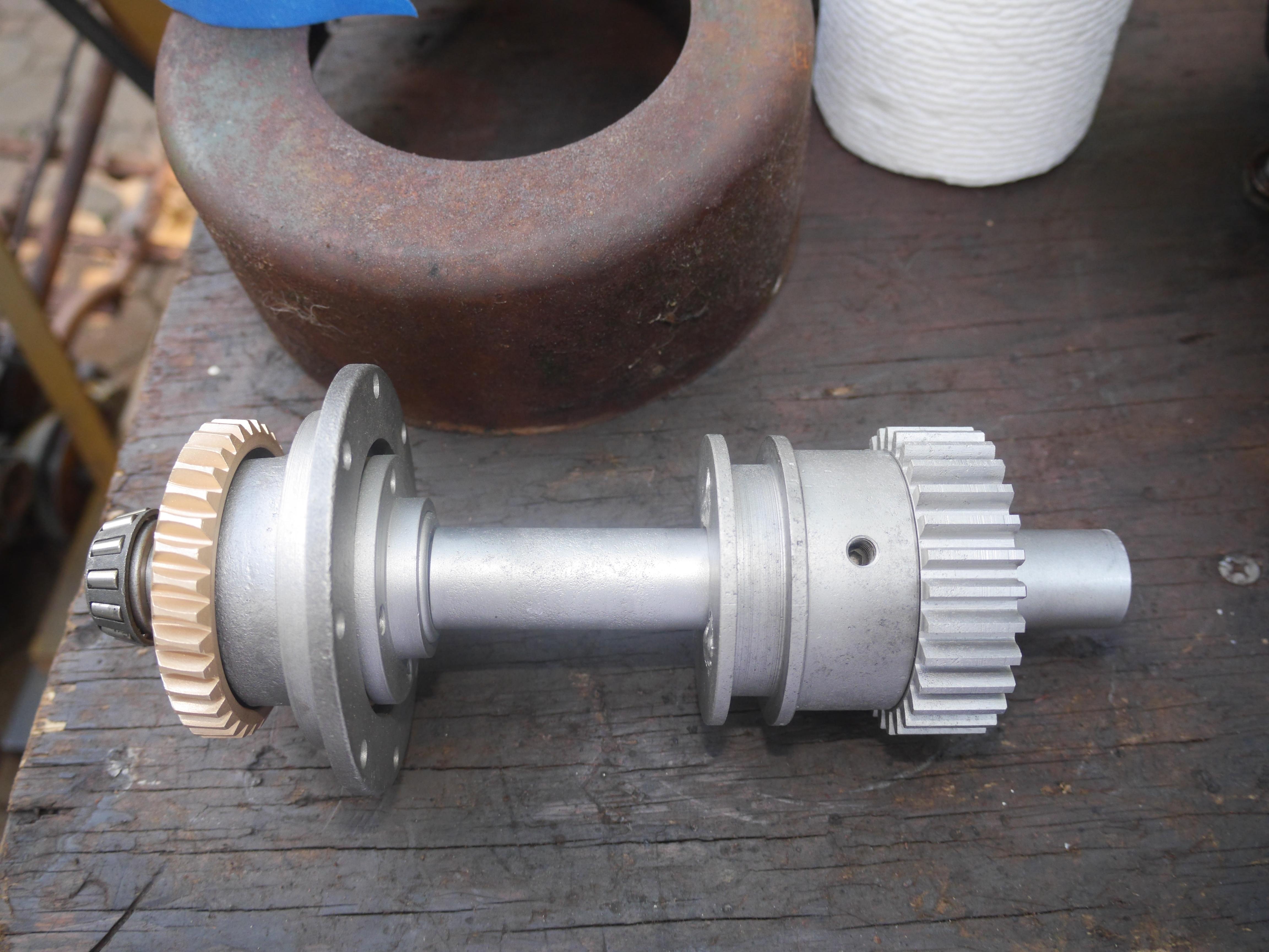
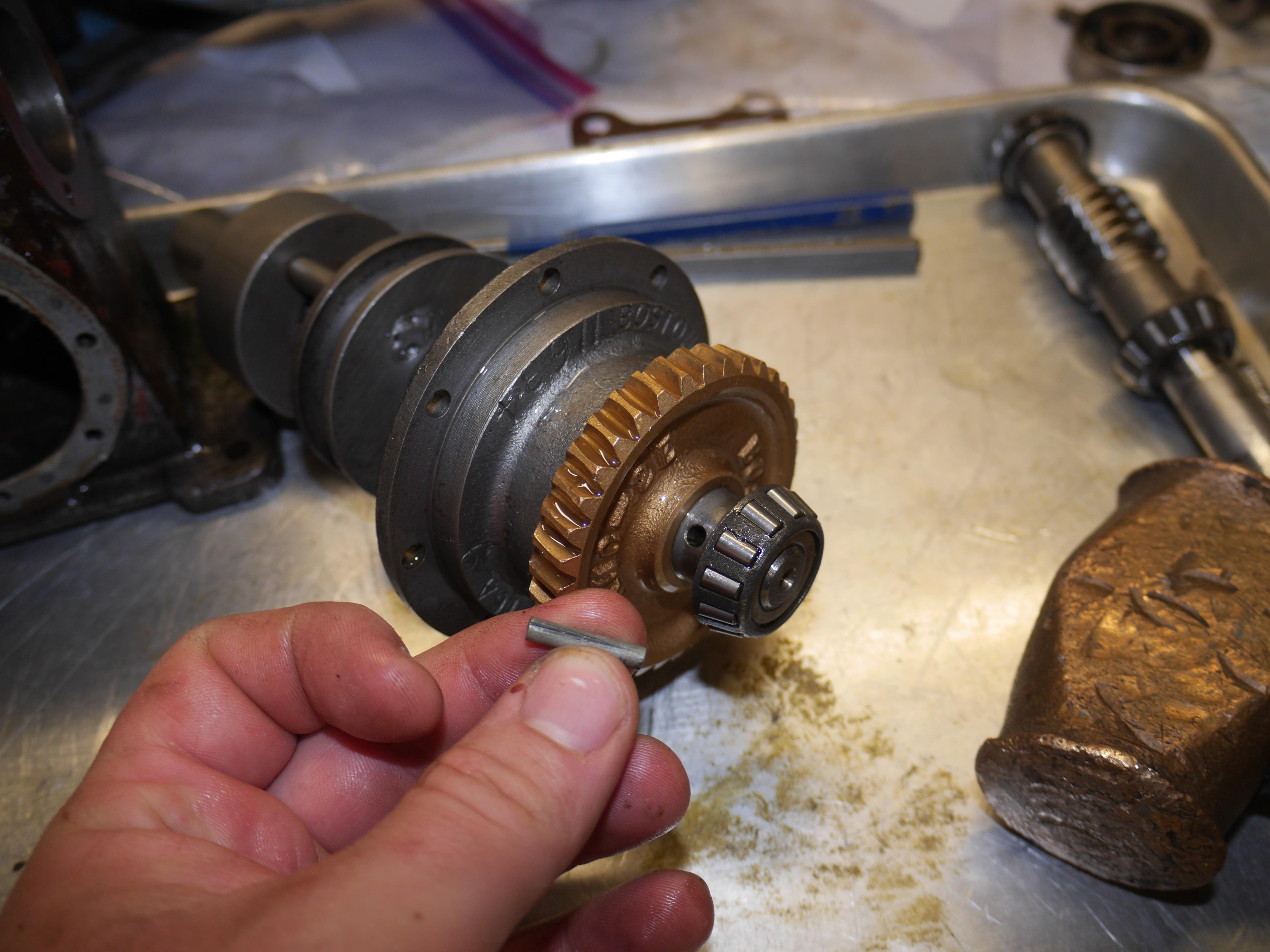
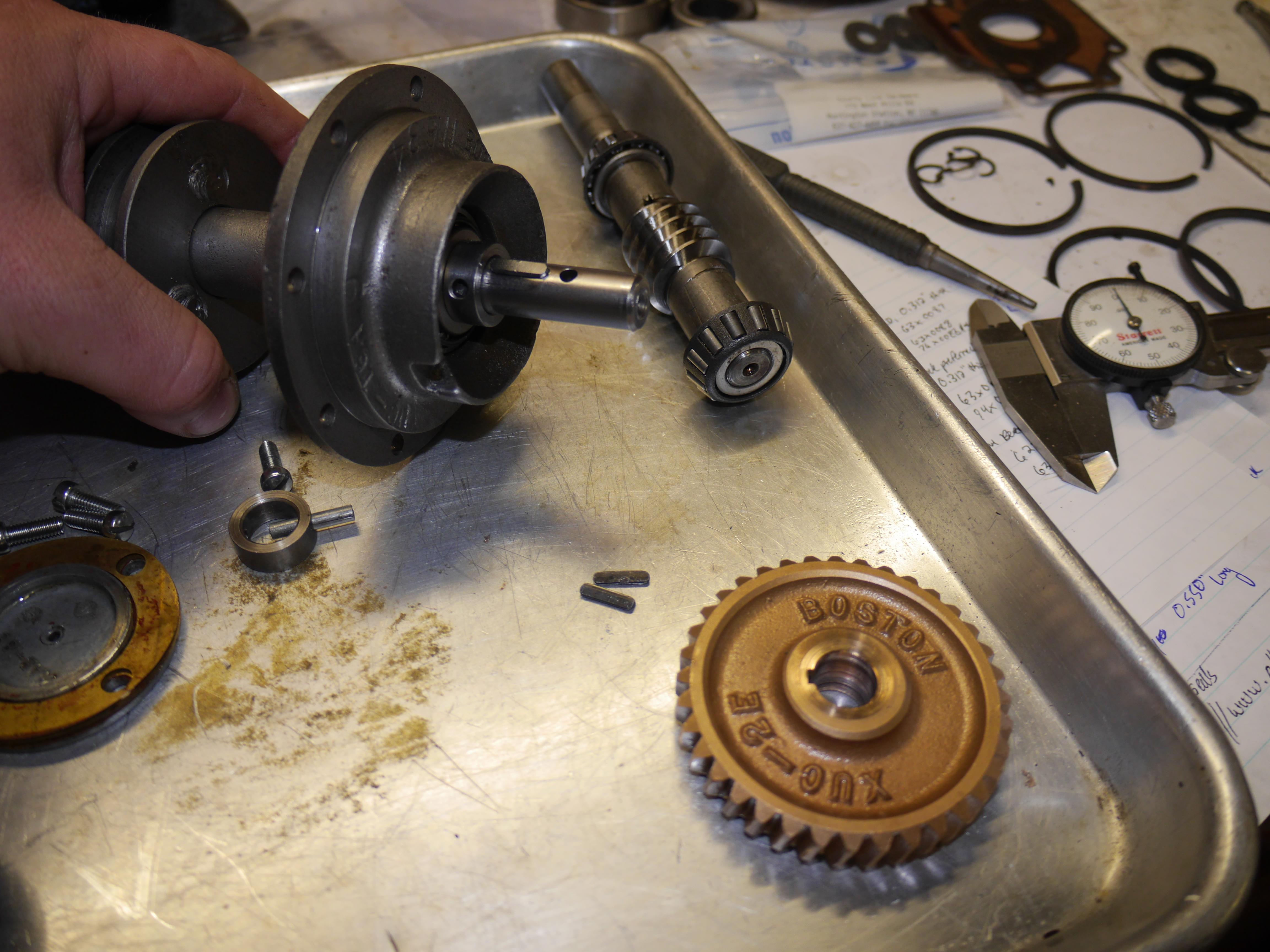
With the axle finished, I could now focus on repairing the original Boston Reductor worm drive. I set out to discover why the worm drive had been taken apart, so apart it came. I drove out the tapered dowel pins, and pulled the bronze worm wheel off of the output shaft. It became evident that the key that secures the bronze worm wheel to the output shaft had sheared. I carefully extracted the remains of the key from the worm wheel, and the output shaft and began making a replacement key.
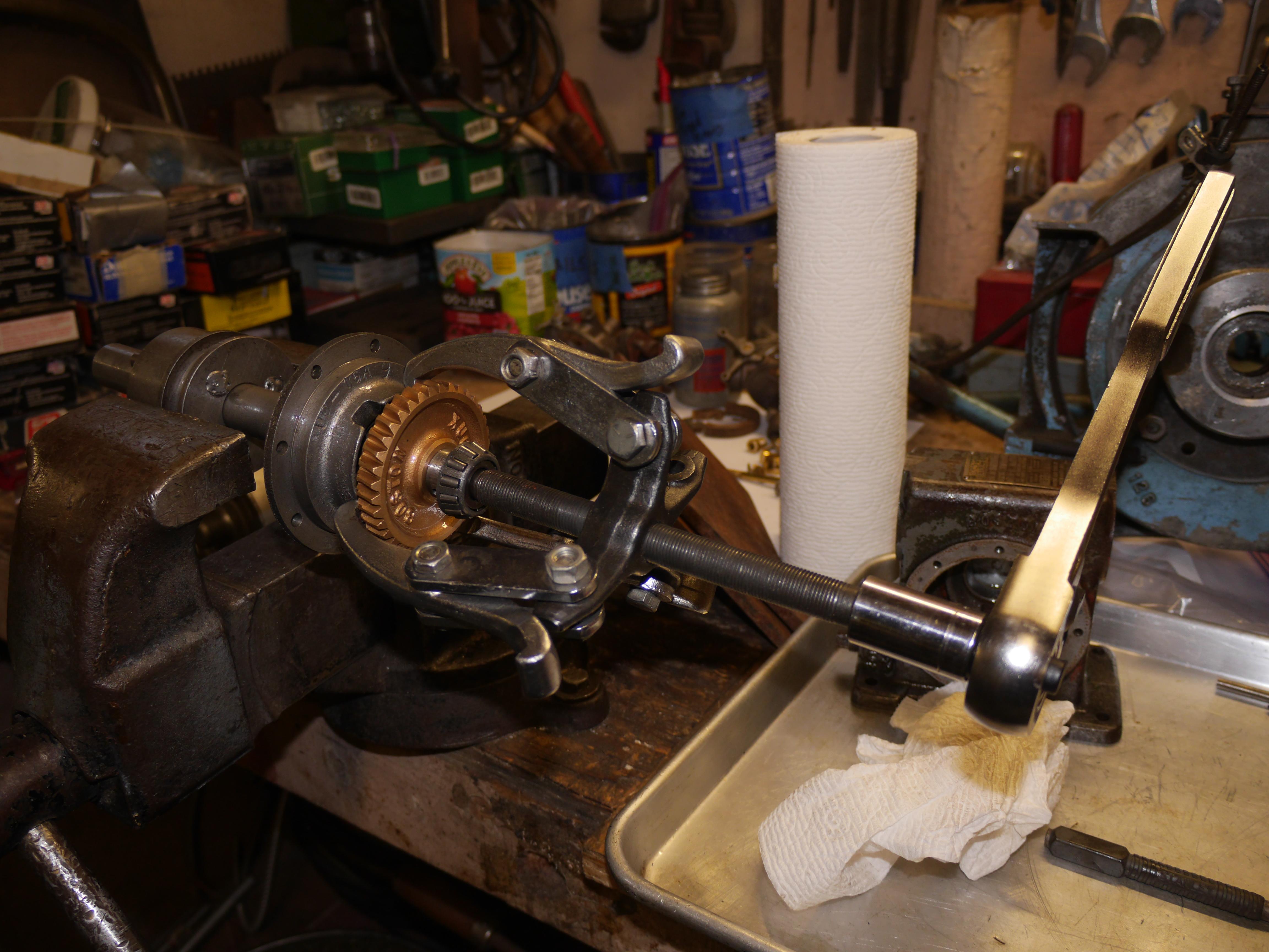
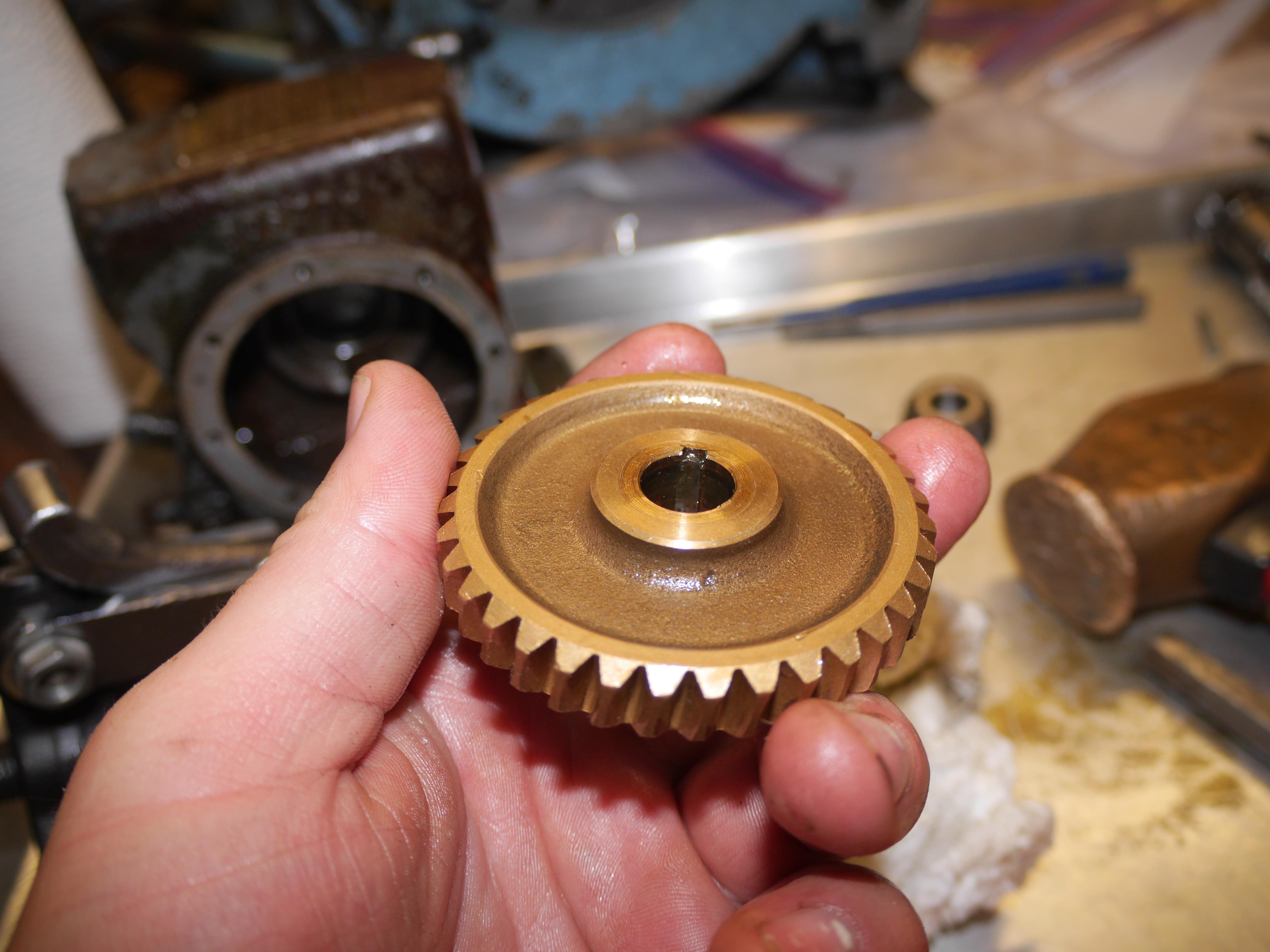
I continued to disassemble the Boston Reductor worm gear box until there was nothing else to remove. Other than the one sheared key, everything looked pretty nice considering this transmission sat open exposed to the elements for probably forty or more years. This can only be attributed to using good quality materials. Every part of this little gearbox is really nice, down to the Timken tapered roller bearings and the Garlock seals. Everything is proudly made in the USA, just the way I like it.
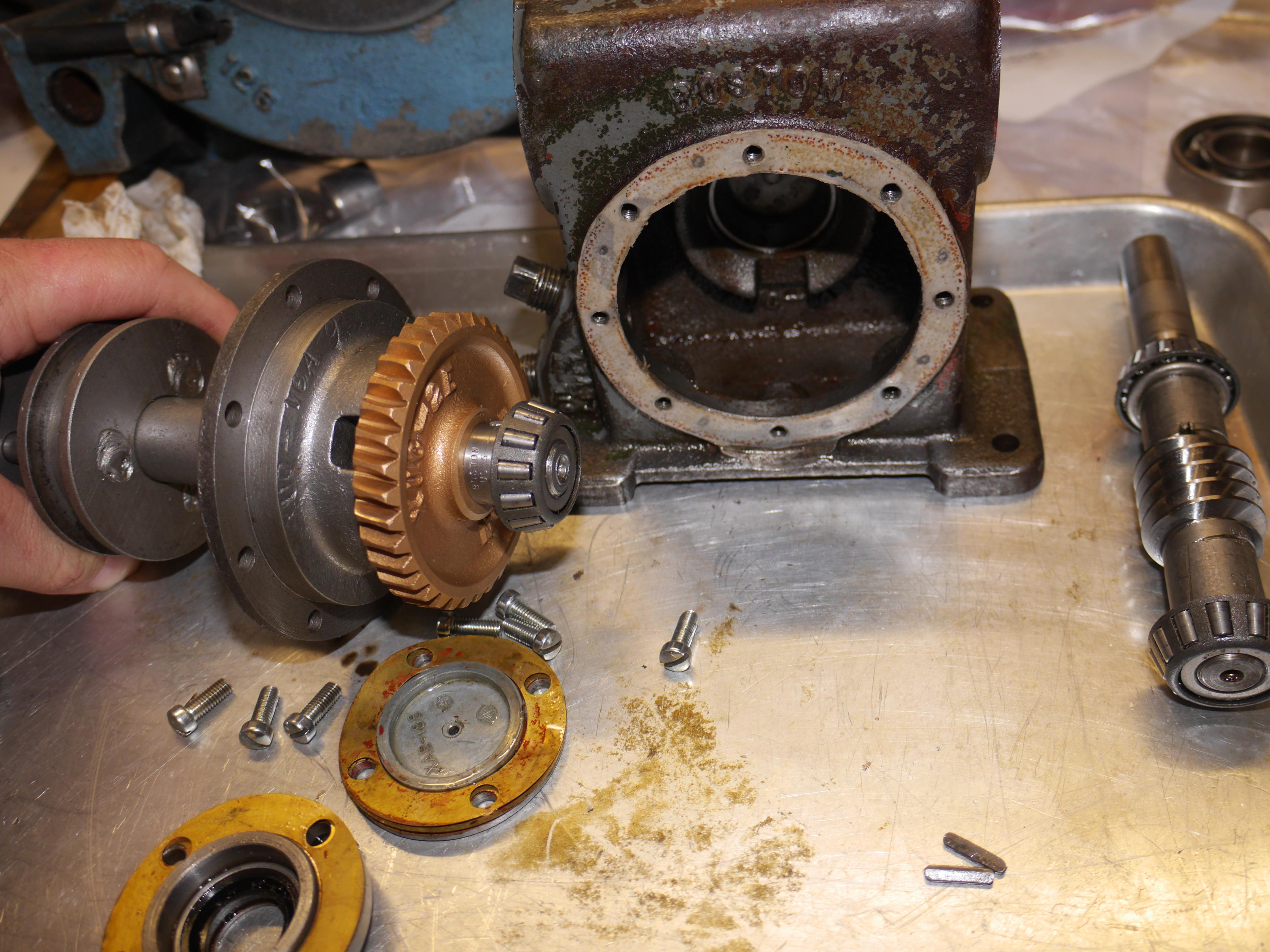
I filled the gear box with the recommended oil, and test ran the worm drive transmission on my lathe for half an hour to make sure everything was working properly and receiving oil before putting it under load. After everything checked out, I mounted the Boston Reductor back in my Maxim snow thrower.

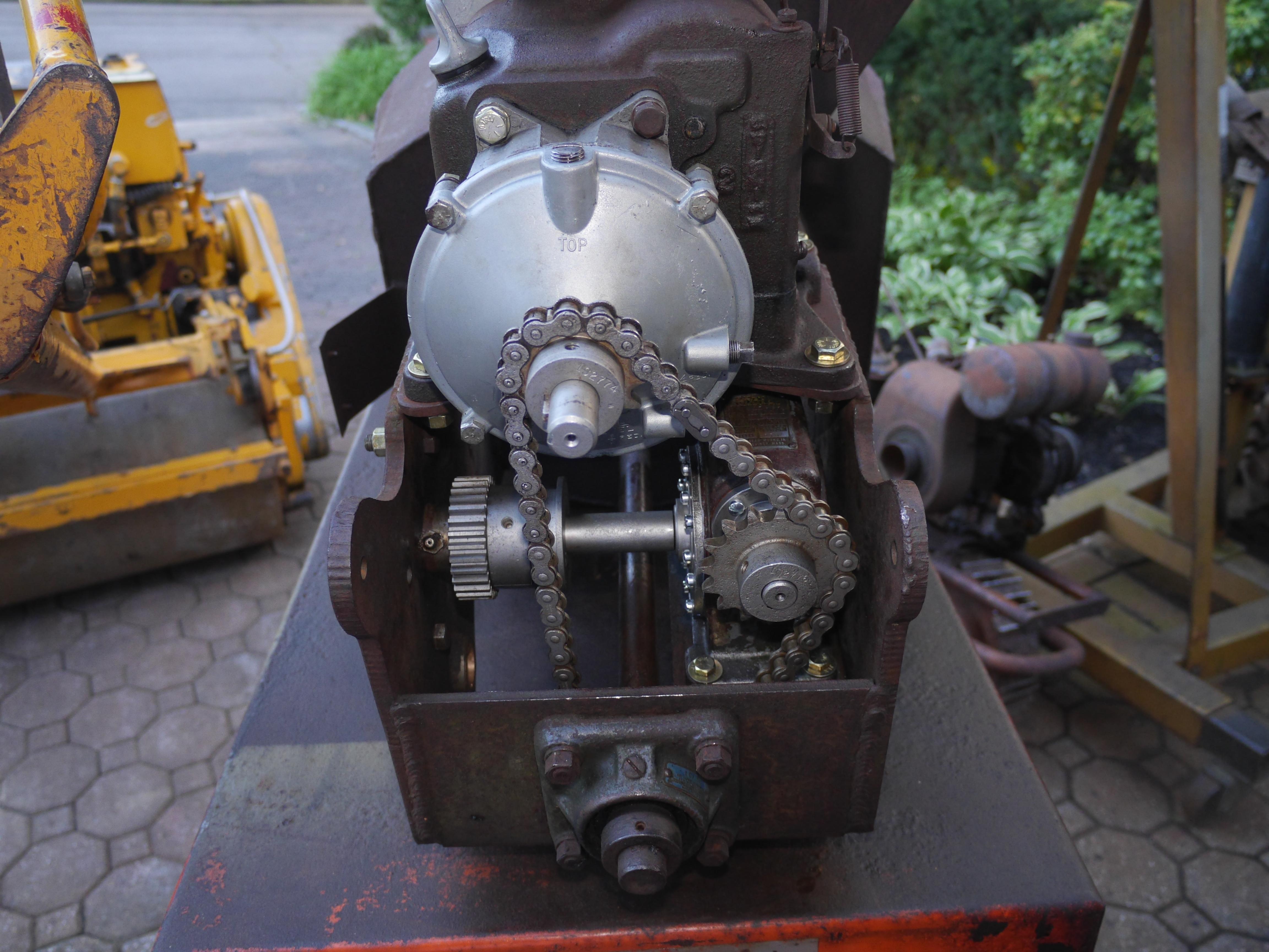
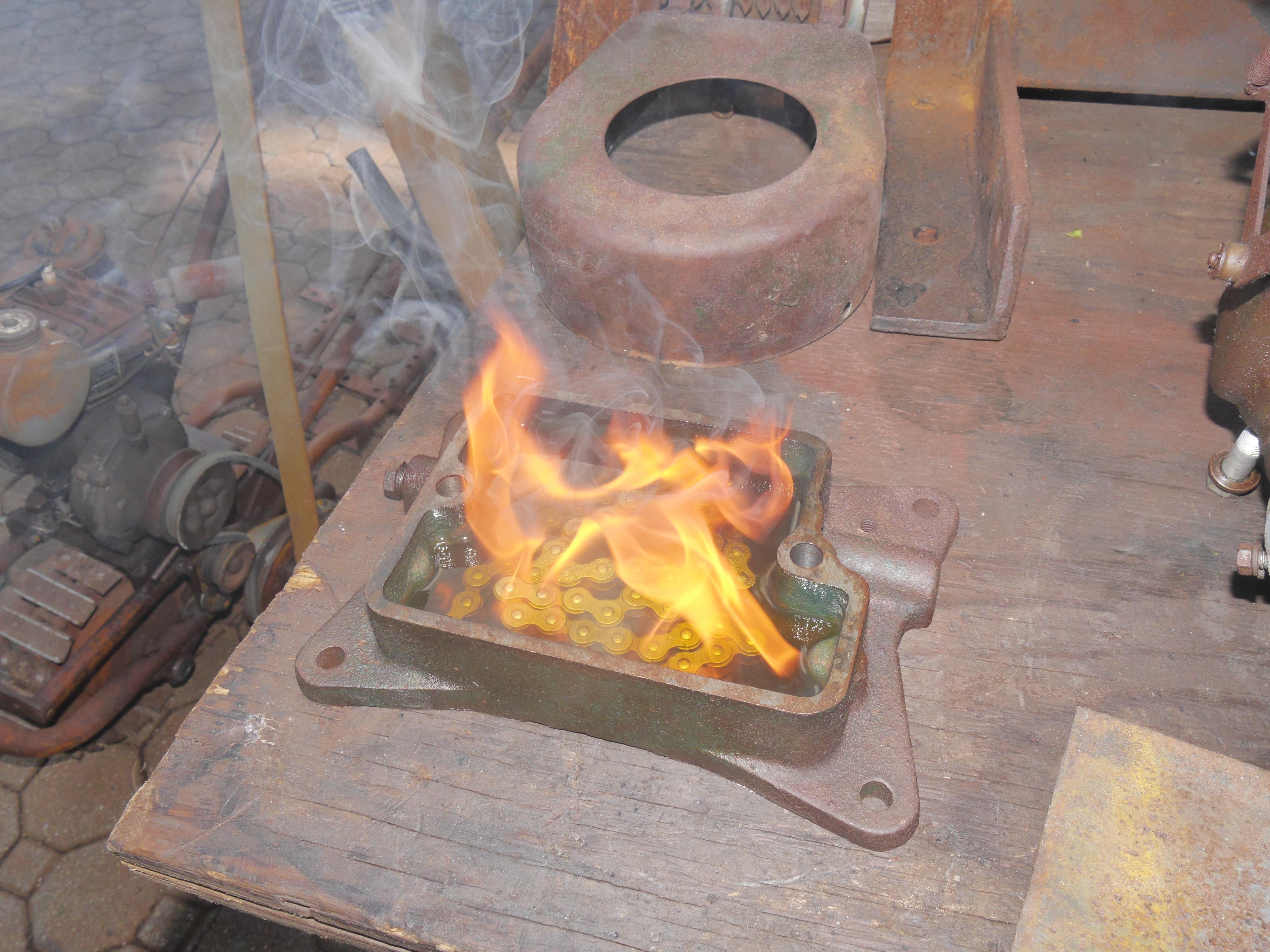
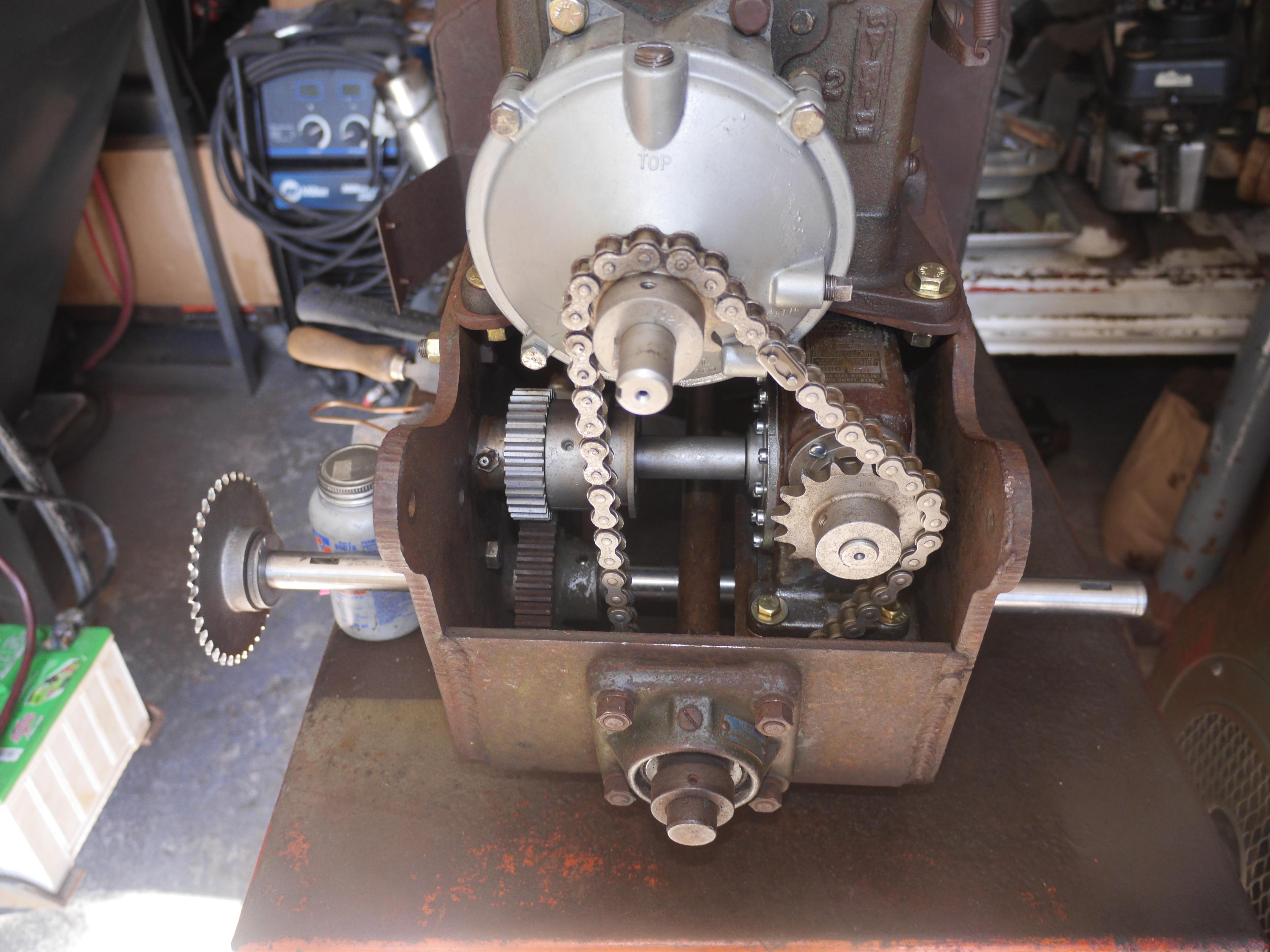
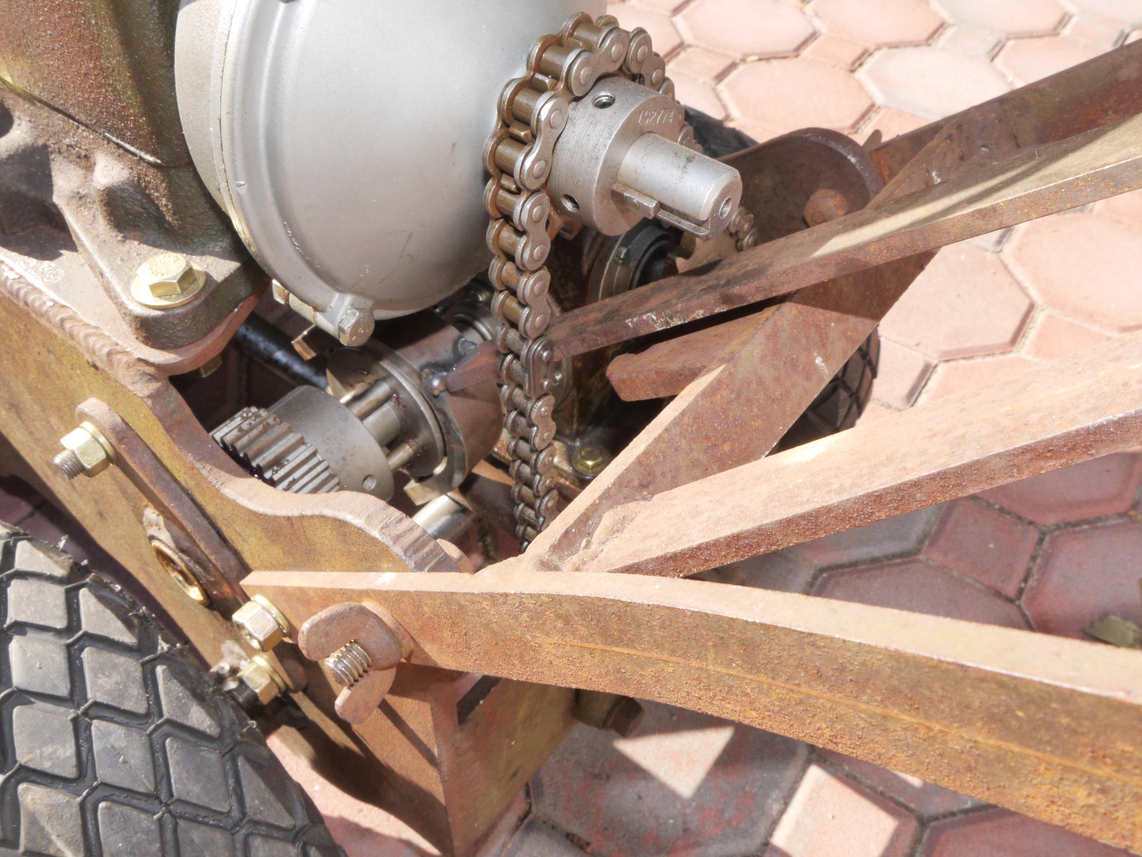
In the last picture you will see that the sprockets and chains are all in place. Believe it or not, but that chain pictured above is the original chain to this machine. As with my other Maxim snow throwers, Maxim used ACME or Pratt& Whitney roller chains on their machinery. This drive chain is an old ACME that has been sitting half in the dirt for longer than I have been alive. After removing the original drive chain from the machine, I spent some time bead blasting the chain so that penetrating oil could work its way into the drive links. I let the chain sit in penetrating oil for quite a while. I often ignited the penetrating oil to heat the chain up nice and hot so that it would get sucked into the pores of the steel. Soaking and heating the chain helped a little, but the chain was still extremely rigid. I put the chain in my heated ultrasonic cleaned for several hours. That really helped. Rust just poured out of the chain until the solution became so murky you could not see what was going on. Still one section of chain refused to cleanup. I ended up using a chain breaker to pull apart several links worth of chain. I wire brushed all of these pieces and replaced what was necessary to make a complete chain. At the end of the day, I ended up only needing to replace the connecting link.

With the transmission mounted, the engine running, the axle repaired and the drive chain free'ed up it was time to refit the axle to the snow thrower. This time around I liberally applied Permatex Anti-Seize between the gear on the axle and the axle shaft. Once the gear was mounted and locked to the shaft, I greased up the oilite bushings on either end of the axle and gave it a whirl. I was very surprised at how slow the axle turns in relationship to the engine.


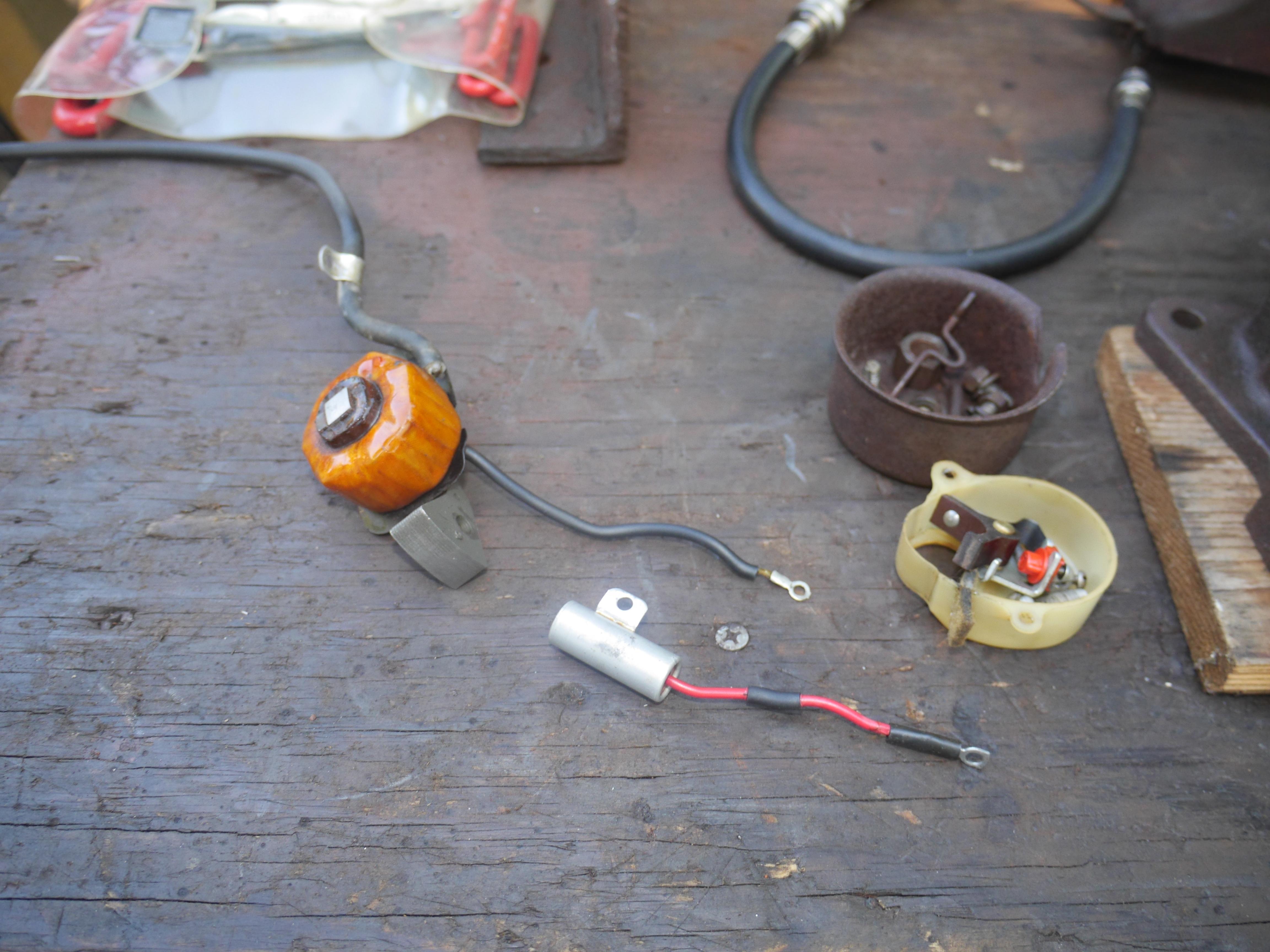
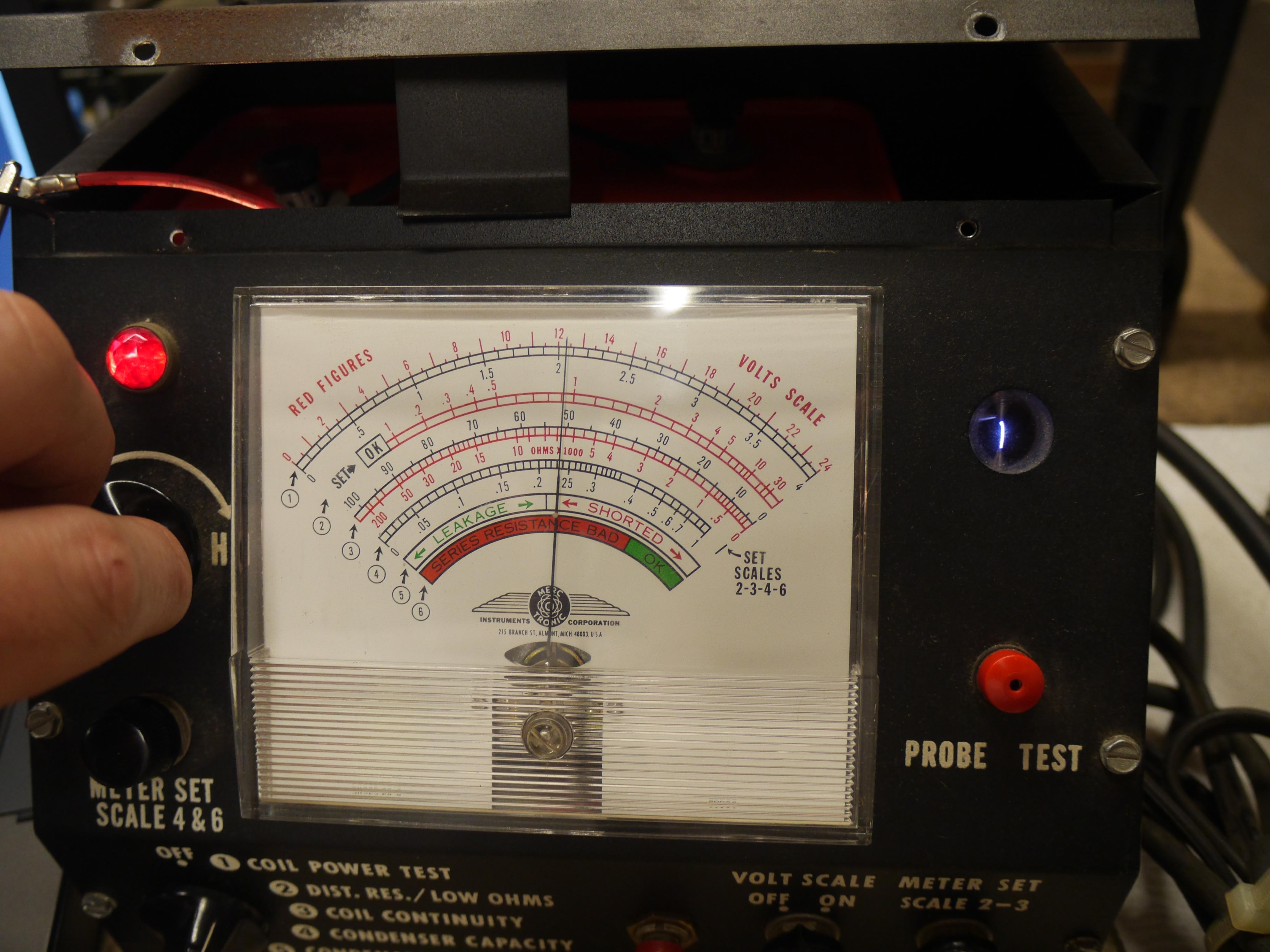
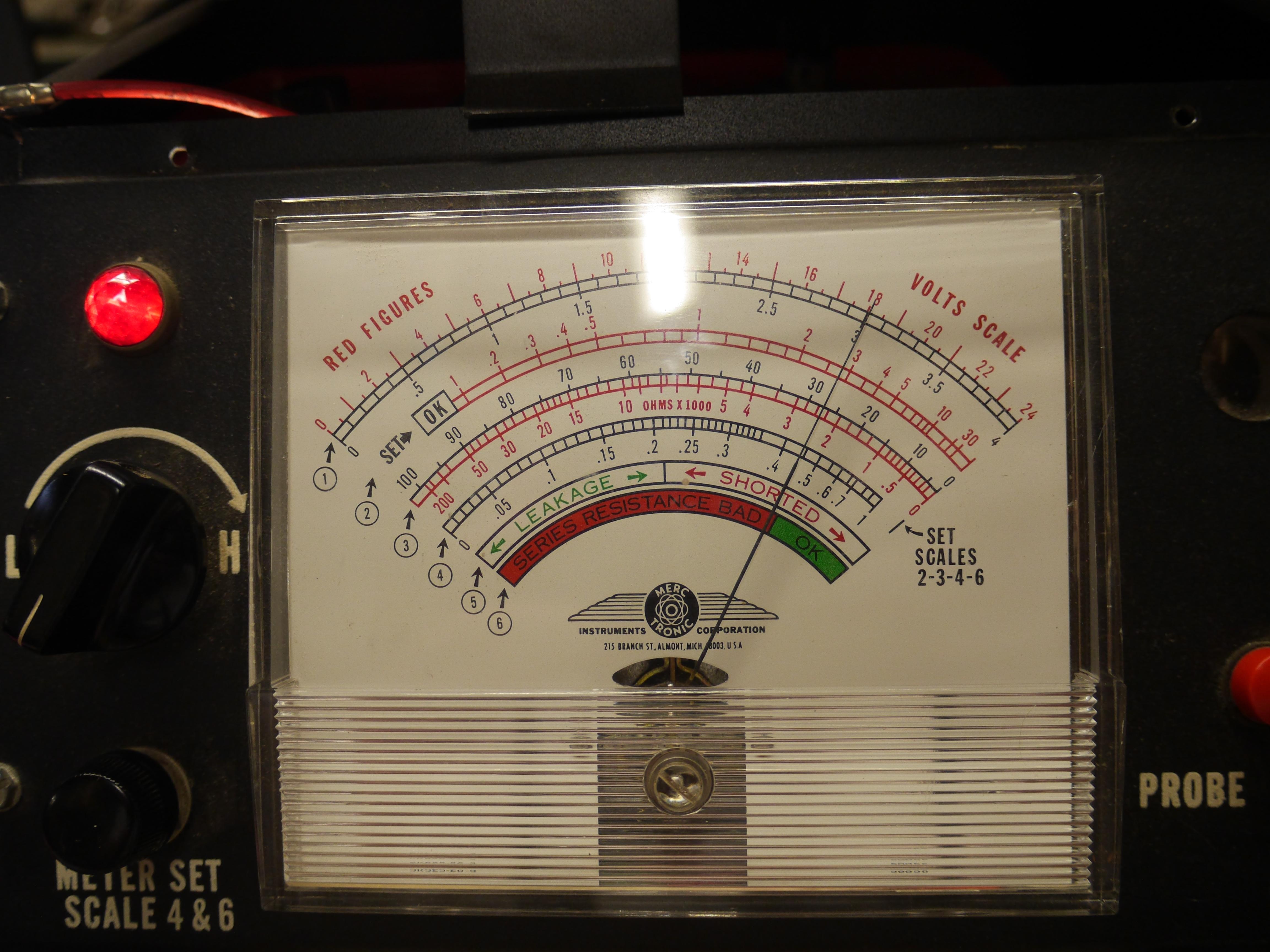
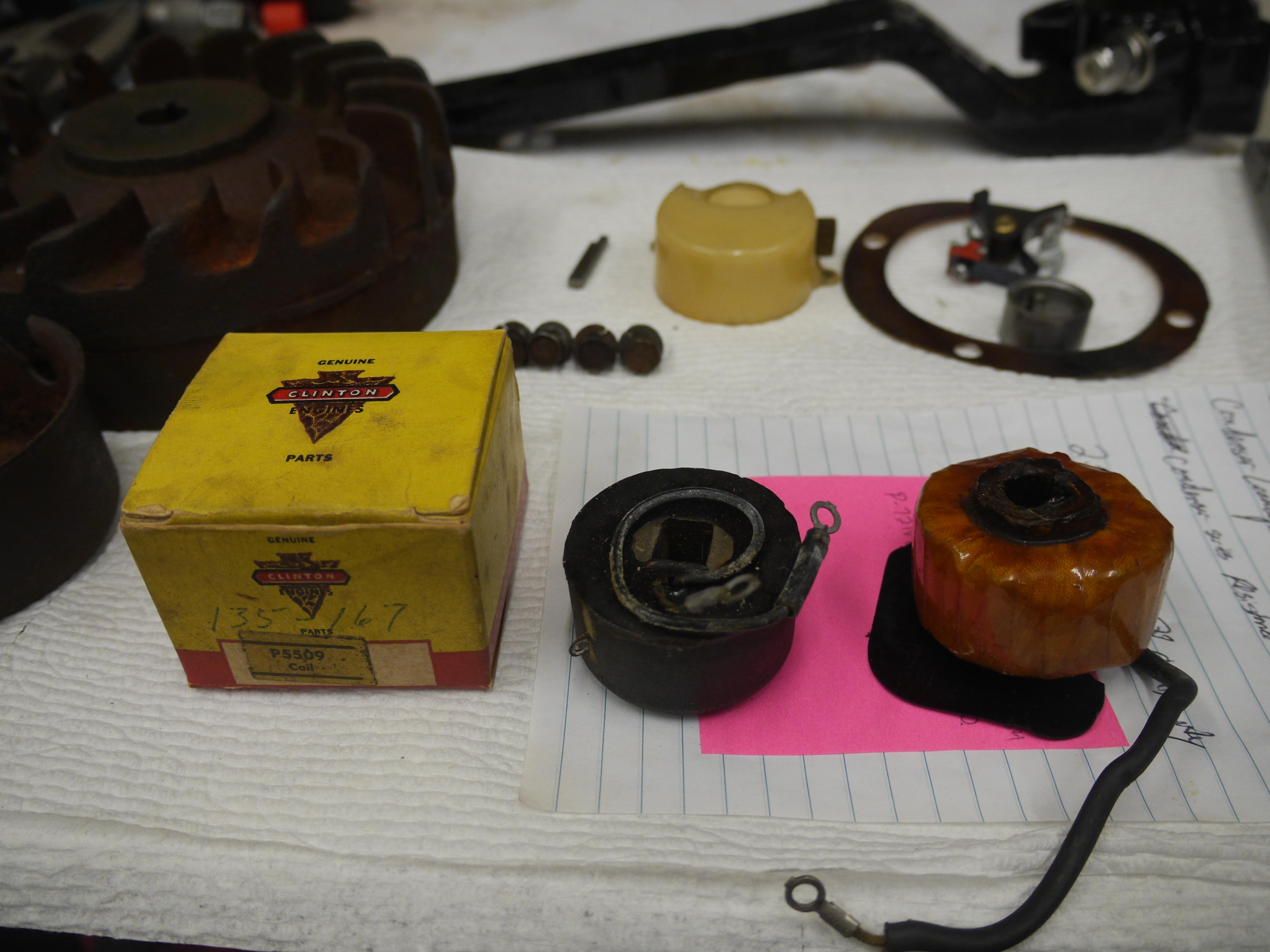
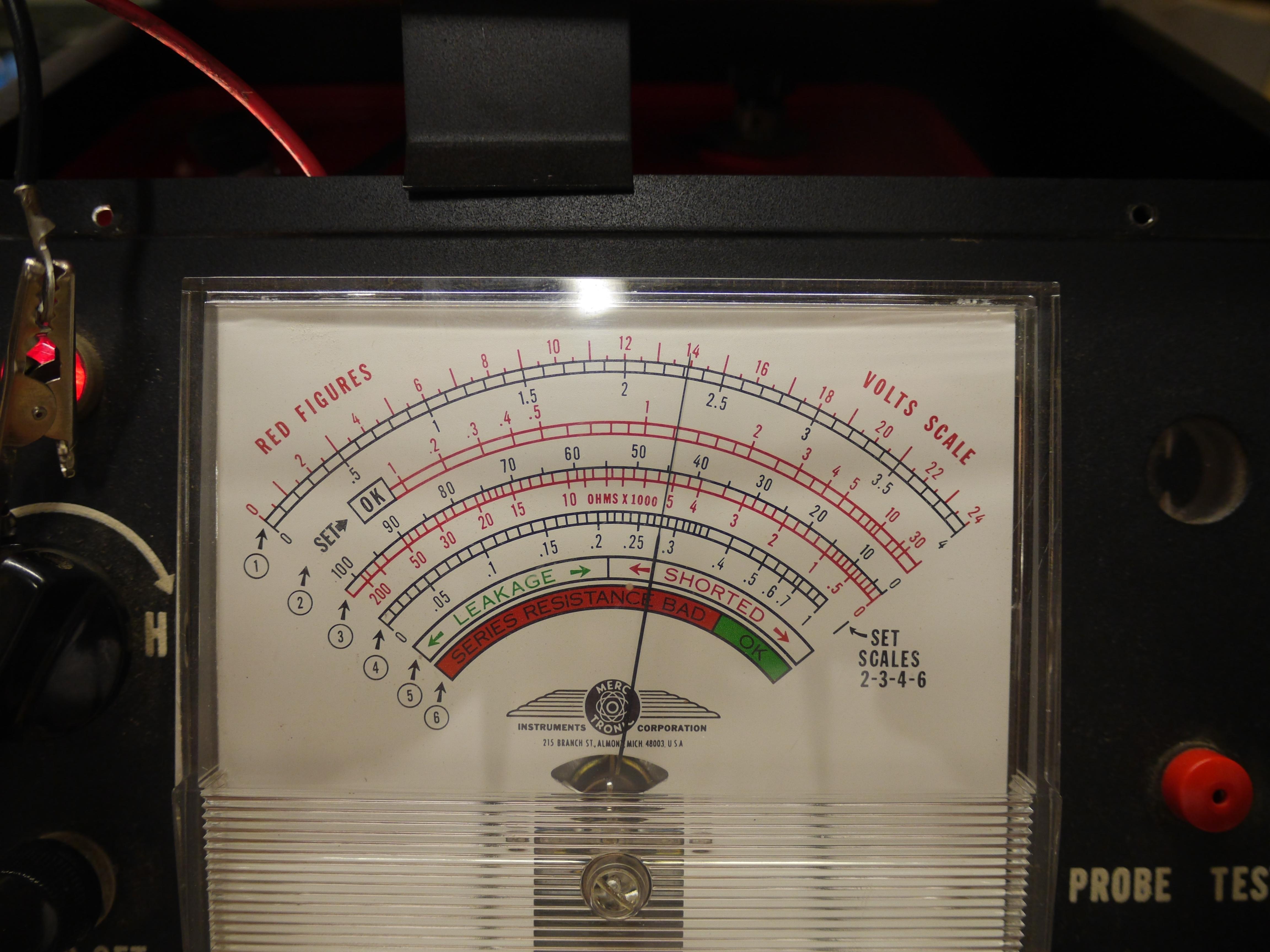
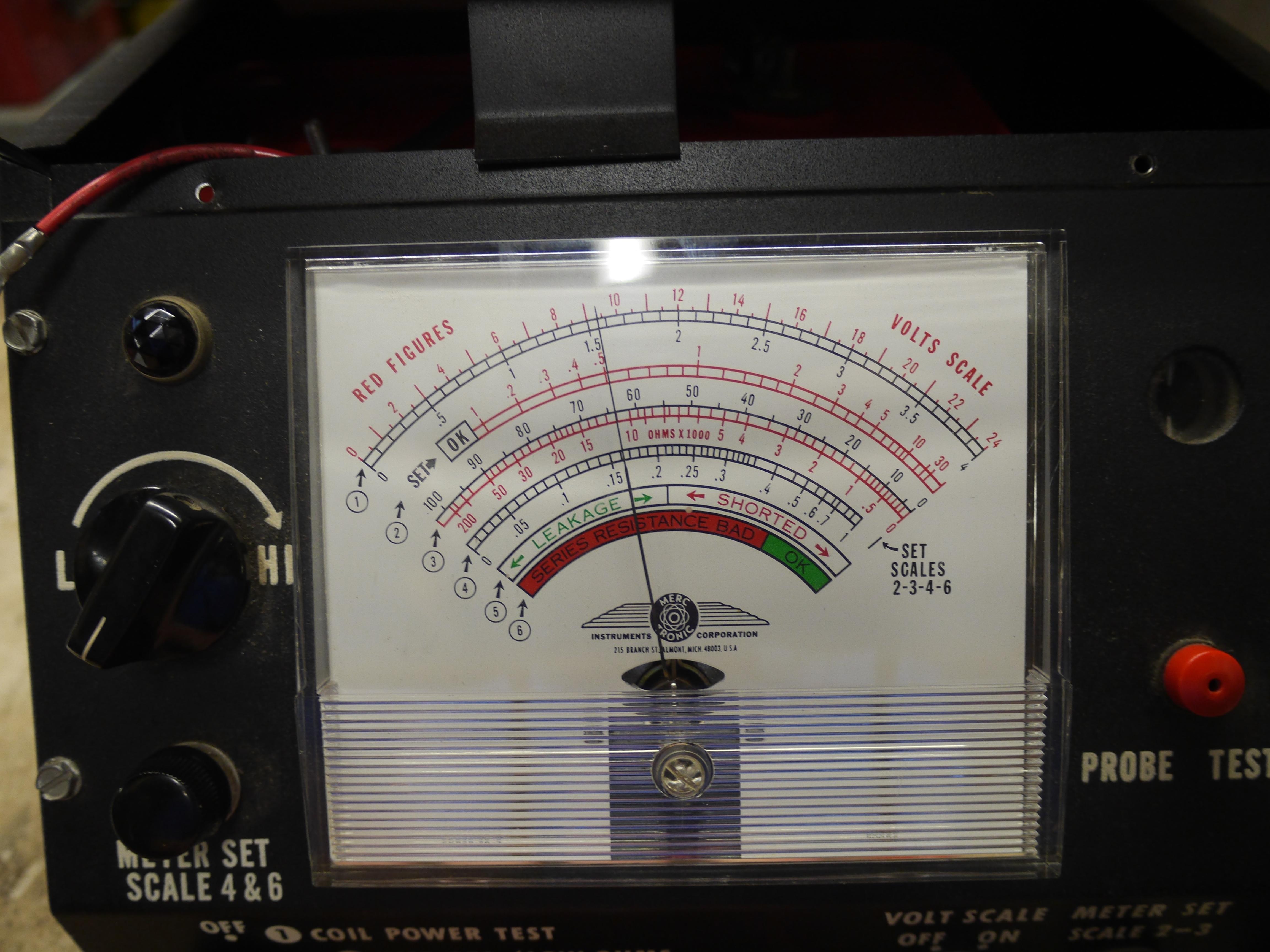
Although the snow thrower was for the most part all back together, the engine had to come back off for ignition work. The engine was simply making no power. I decided to setup my 1960s Merc-O-Tronic ignition testing machine and test the coil and the condenser instead of just replacing parts on a whim.
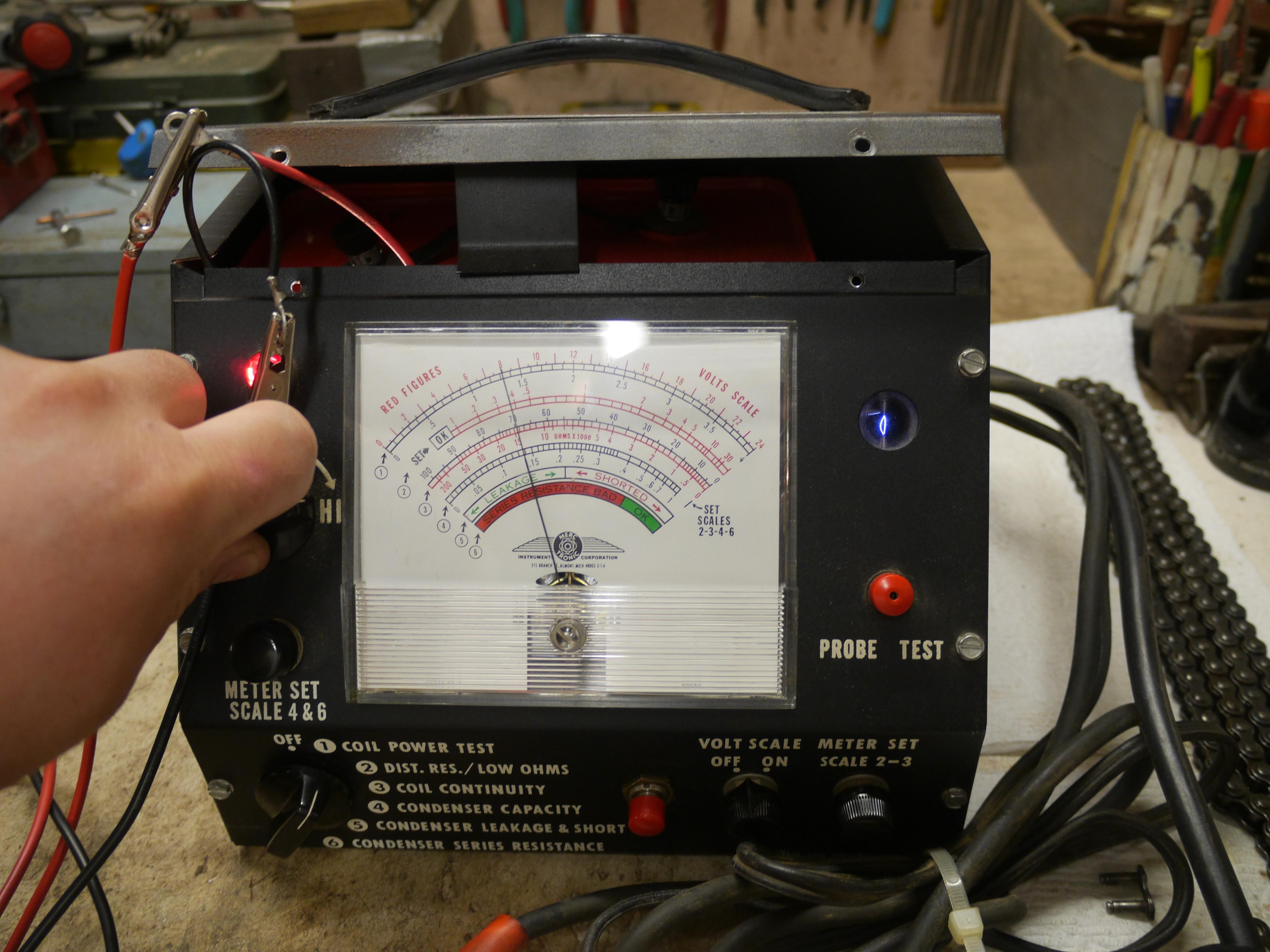
Testing the primary windings of the original Clinton B740 coil:
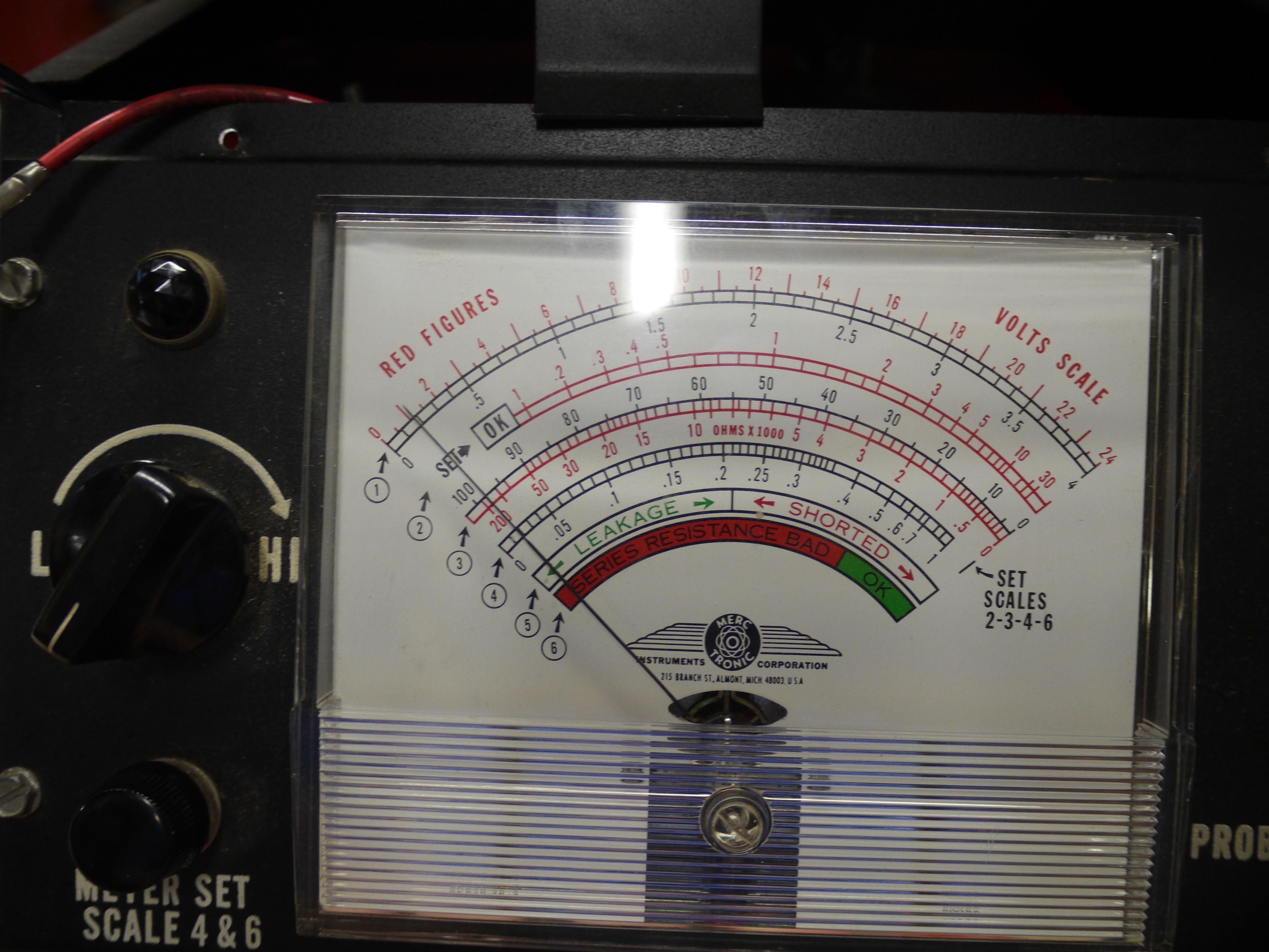
Testing the secondary windings of the original Clinton B740 coil:
Testing the original Clinton B740 condenser:
My tests show that the secondary windings in the original coil are shorted, and that the condenser is internally shorted. Since the tungsten on the points is also in bad shape, every component of the ignition system on this engine has to be replaced. A coil with shorted secondary windings will fail at high speed operation, just as my videos have proved. The condenser was marginal at best, and the fact that it is internally shorted only tells me to replace it.
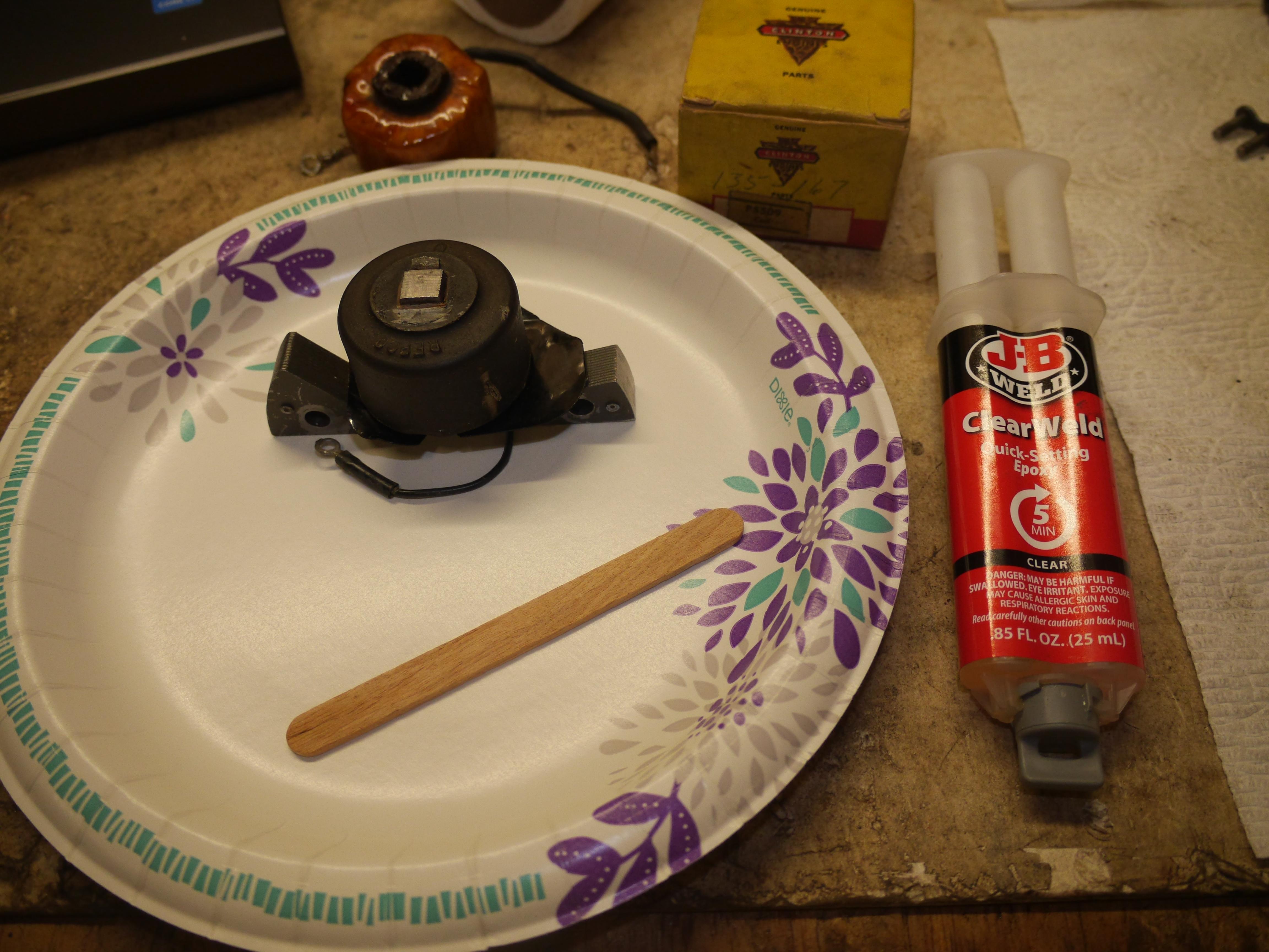
I ordered away for a new Clinton P5502 replacement ignition coil the P5509. The P5509 is the same coil just sold without the laminations. Removing the old coil from the laminations was not very difficult, but putting the new one back on was. I worked hard trying not to damage the approximately fifty year old part while sliding it over the laminations. A little piece of the insulation chipped off when the body of the coil slid over the bump in the lamination that keeps the coil from moving up and down. A light protective coating of JBweld clear epoxy was the ticket to re-sealing the coil.

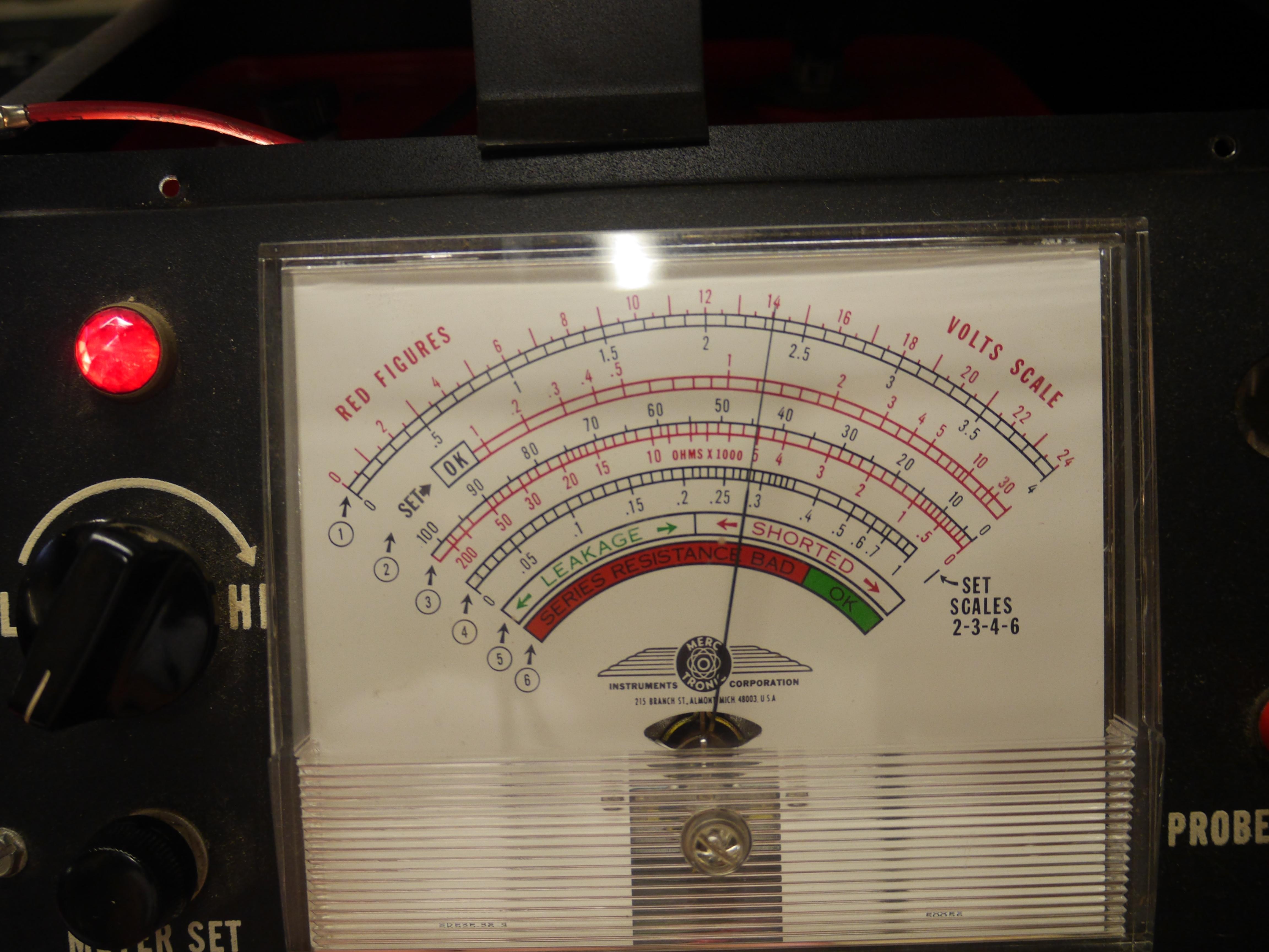
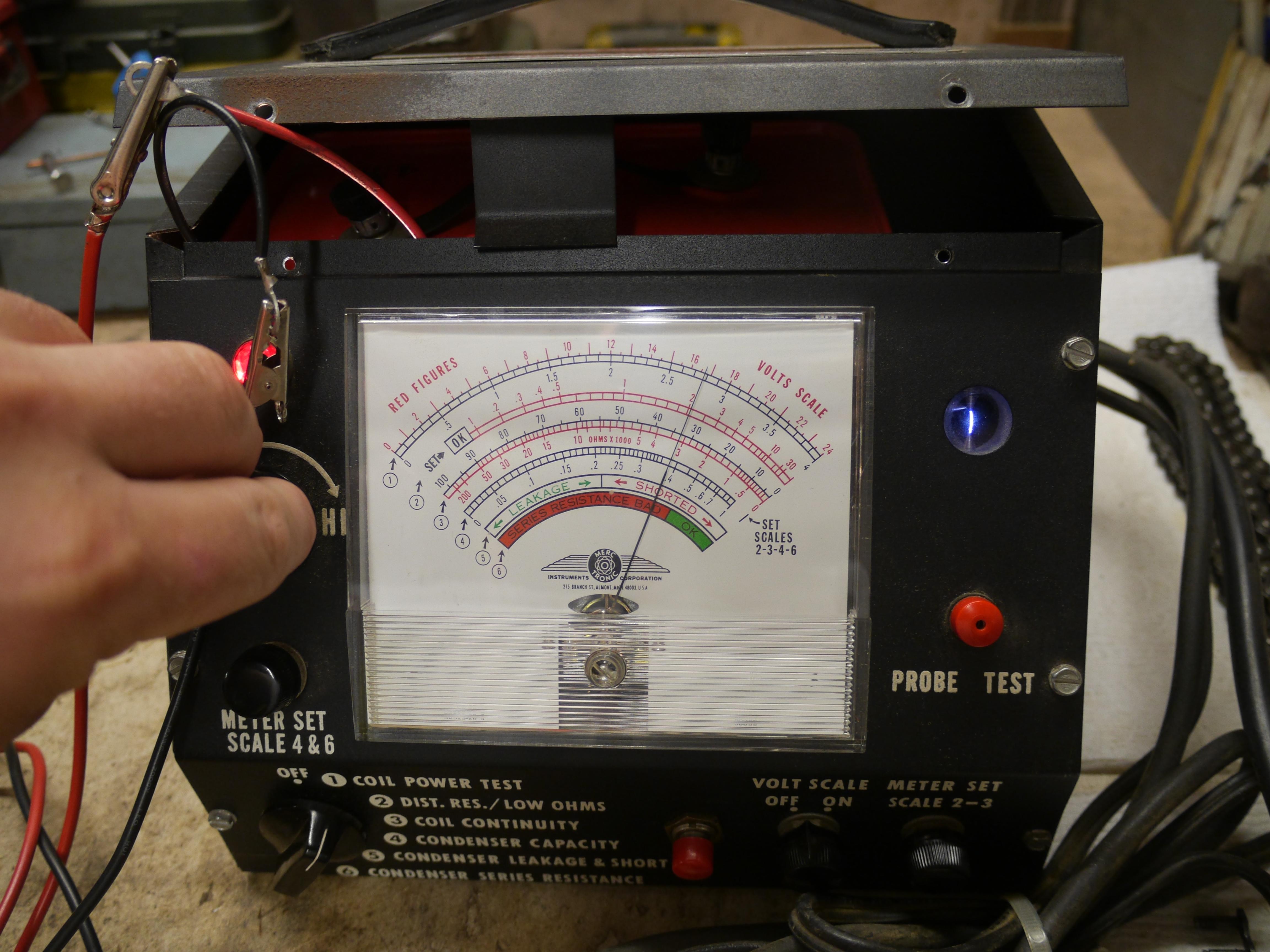
Before installing the new coil back on the engine I tested the new coil with my Merc-O-Tronic ignition testing machine. This new coil was perfectly in spec. It had a nice fat consistent blue spark at 1.3 amps all of the way up to its rated 2.8 amps and beyond. When I tested the secondary windings the coil was right in spec at 45 ohms of resistance.
Testing the primary windings of the new Clinton P5509 coil:
Testing the secondary windings of the new Clinton P5509 coil:
Now that I have a tested good ignition coil, I took this opportunity to remove and clean the front bearing plate/ignition mounting plate for the engine. After a quick bead blasting and cleaning I began reassembling the ignition plate. I mounted the replacement coil and made up a new high tension plug wire for the spark plug. The original plug wire was partially eaten, spliced and in bad shape. I replaced it with some top of the line Packard 440 solid copper core high tension plug wire. I tinned the end of the wire that goes into the coil. It is good practice to tin the end of the wire going into the coil so that when you slip it through the hole in the high tension terminal you can quickly solder the wire in place without putting too much heat into the coil.
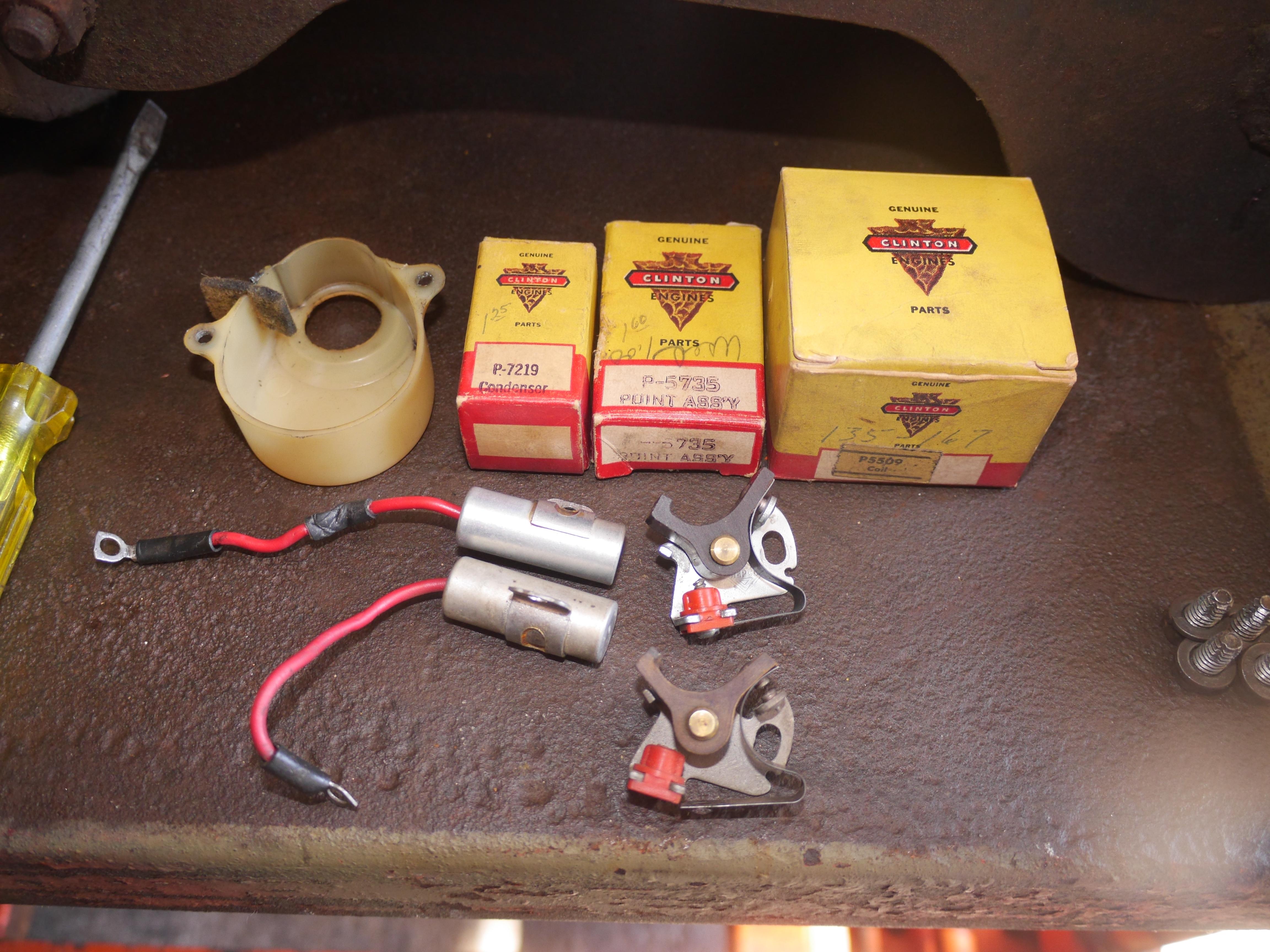
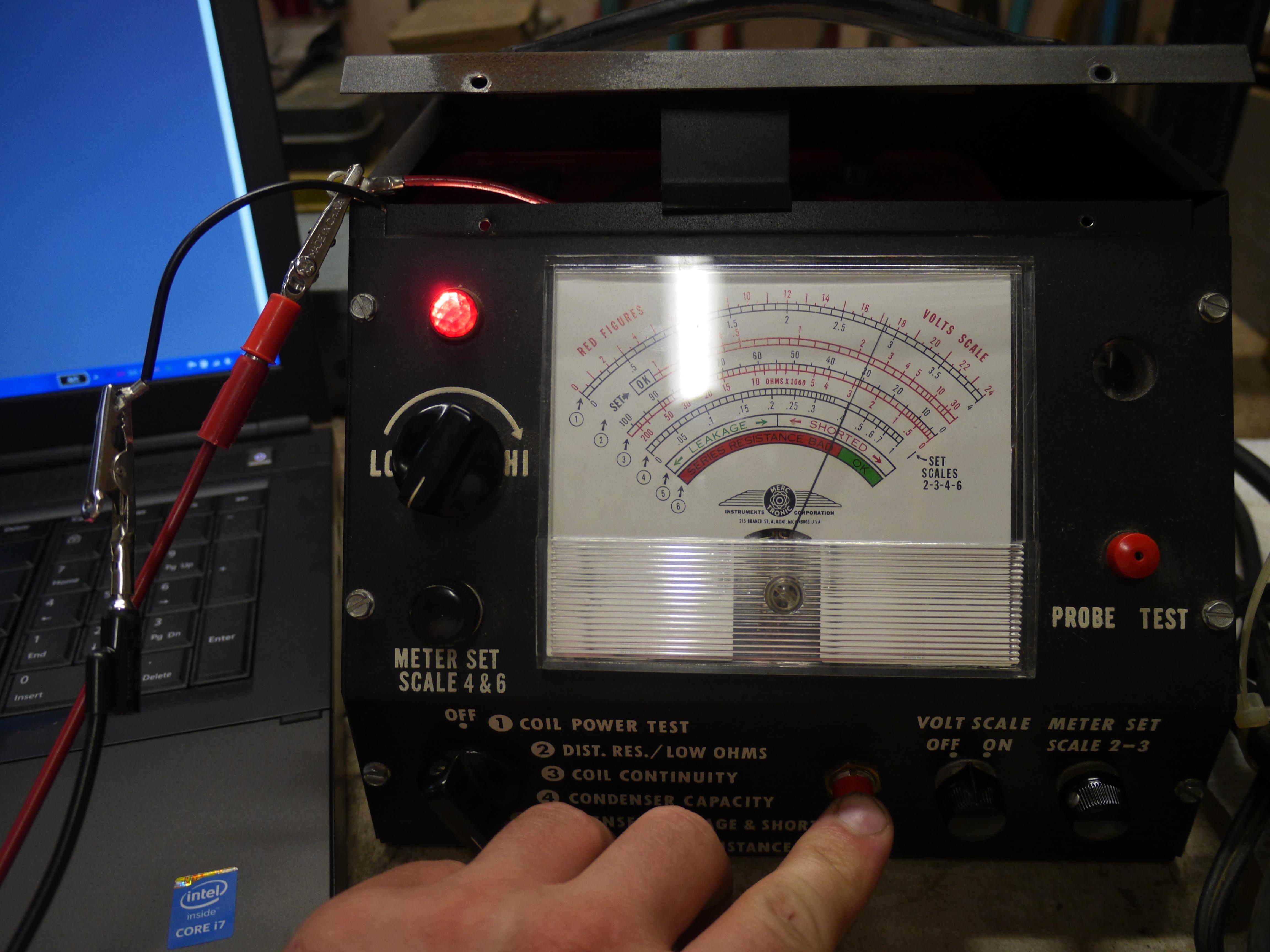
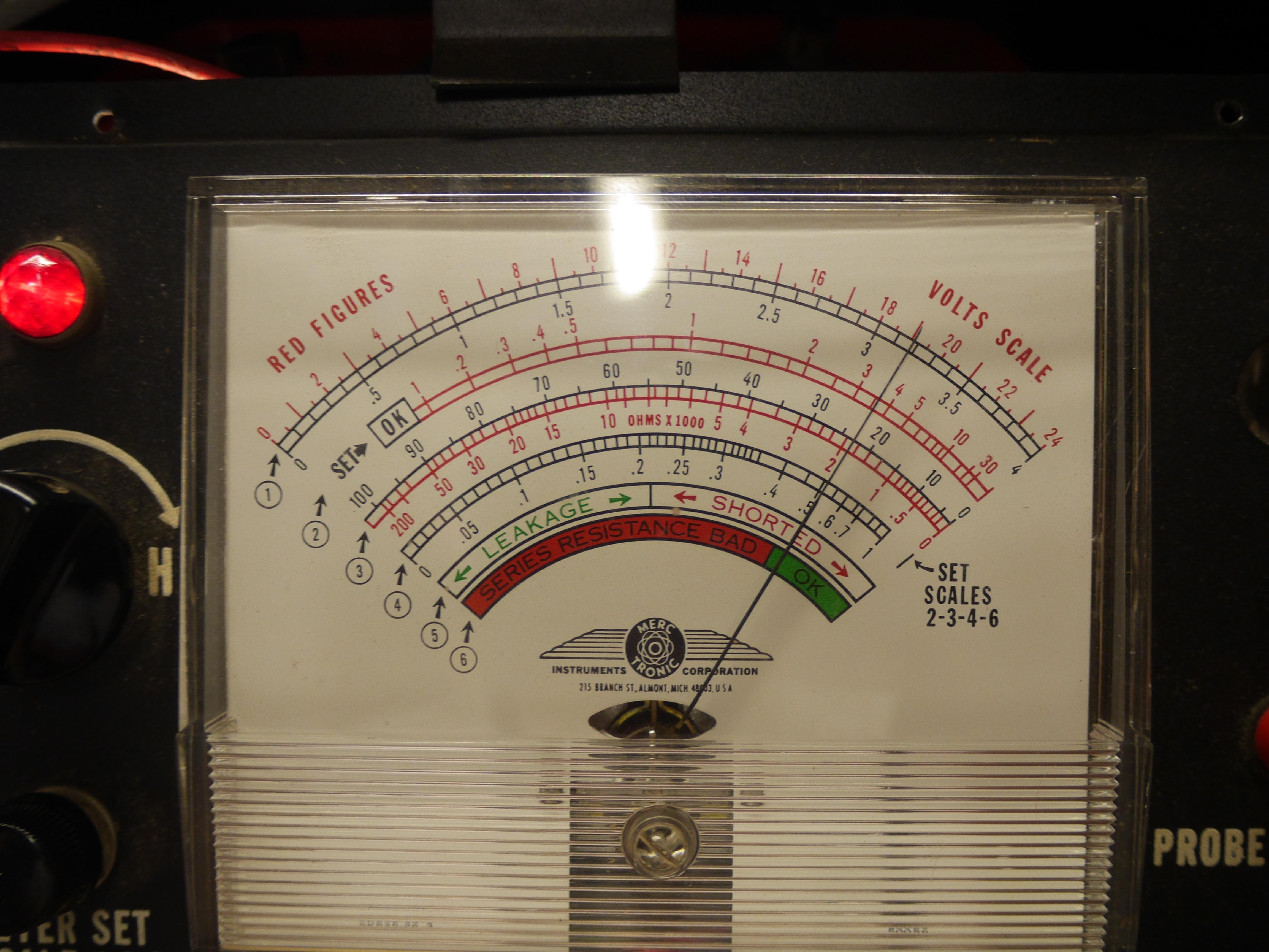
The new replacement REPCO FG-410D (Clinton P7219) condenser arrived, so I took this opportunity to test it with the Merc-O-Tronic. The new condenser tested in at 0.16MFD capacity, right on spec. The new condenser passed the leakdown test and proved that the condenser was not internally shorted. The new condenser failted the series resistance test, but I believe that is because the internal capacitor in the Merc-O-Tronic is dead and it is comparing itself to a dead capacitor rather than a known good one.
Testing the new REPCO FG-410D condenser:

I set the new Clinton P-5735 points at 0.018" just as the book suggests, and hooked up the new condenser.
After buttoning up the ignition system, I turned the fuel on and started the engine. To my surprise it started up like it was running a few minutes early. It just ran absolutely perfect. It idled fine and ran great throughout its entire rpm range. First run of the Clinton B740 with the new coil, points and condenser:
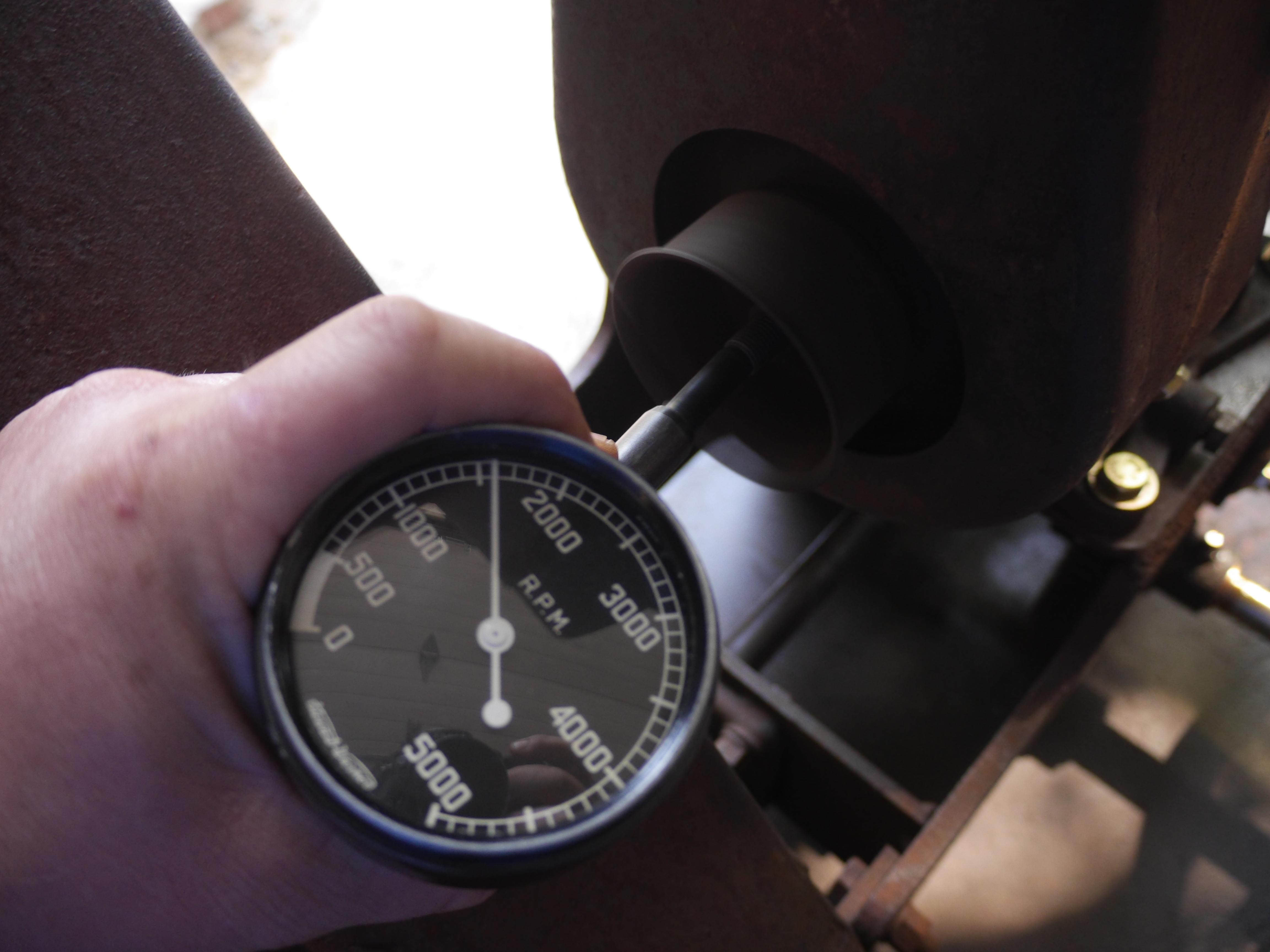
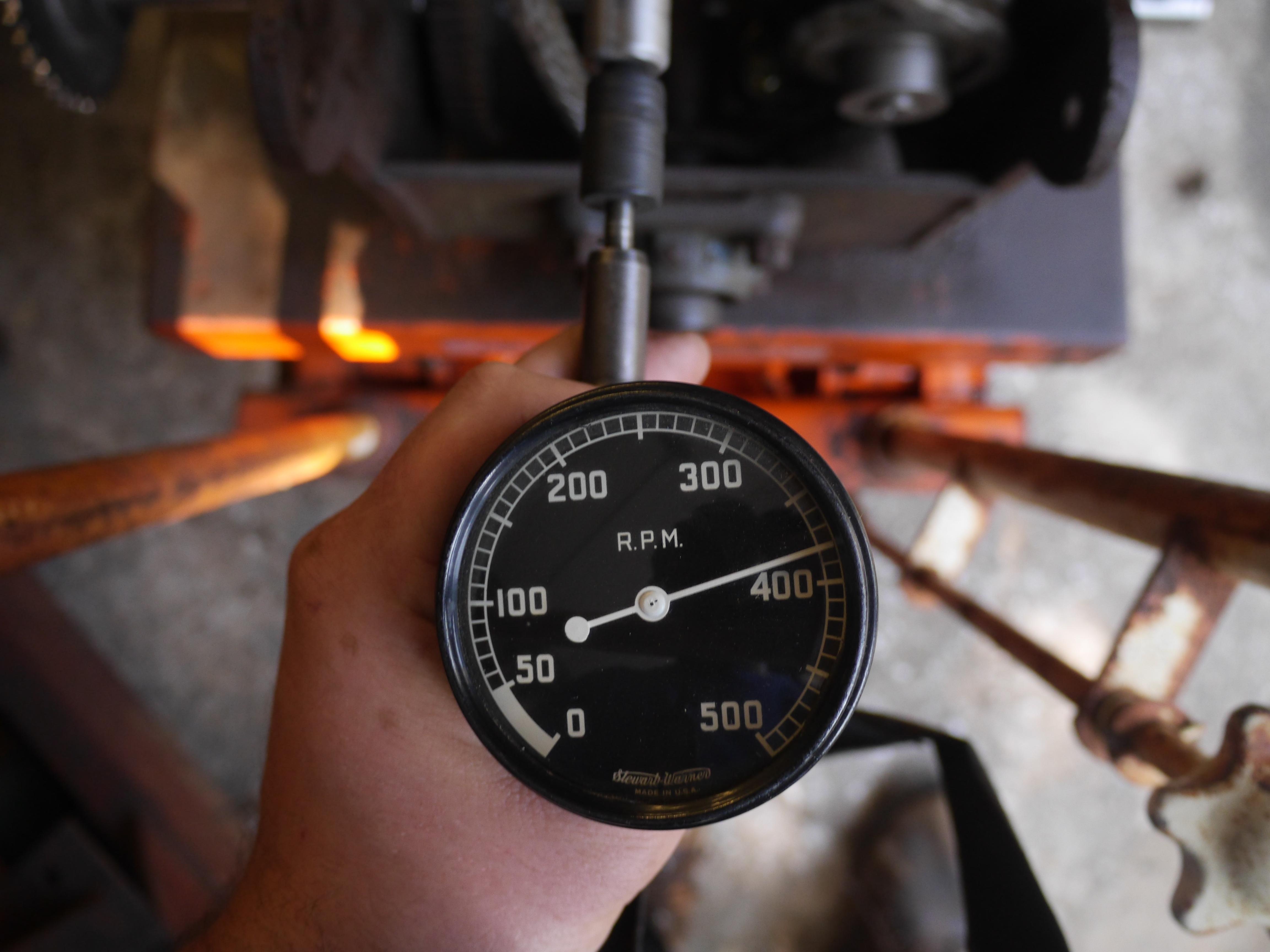
As you can see the engine really runs nice now. It idles at 1600rpm and runs fine up to its governed speed and beyond. I couldnt be happier with how it runs.
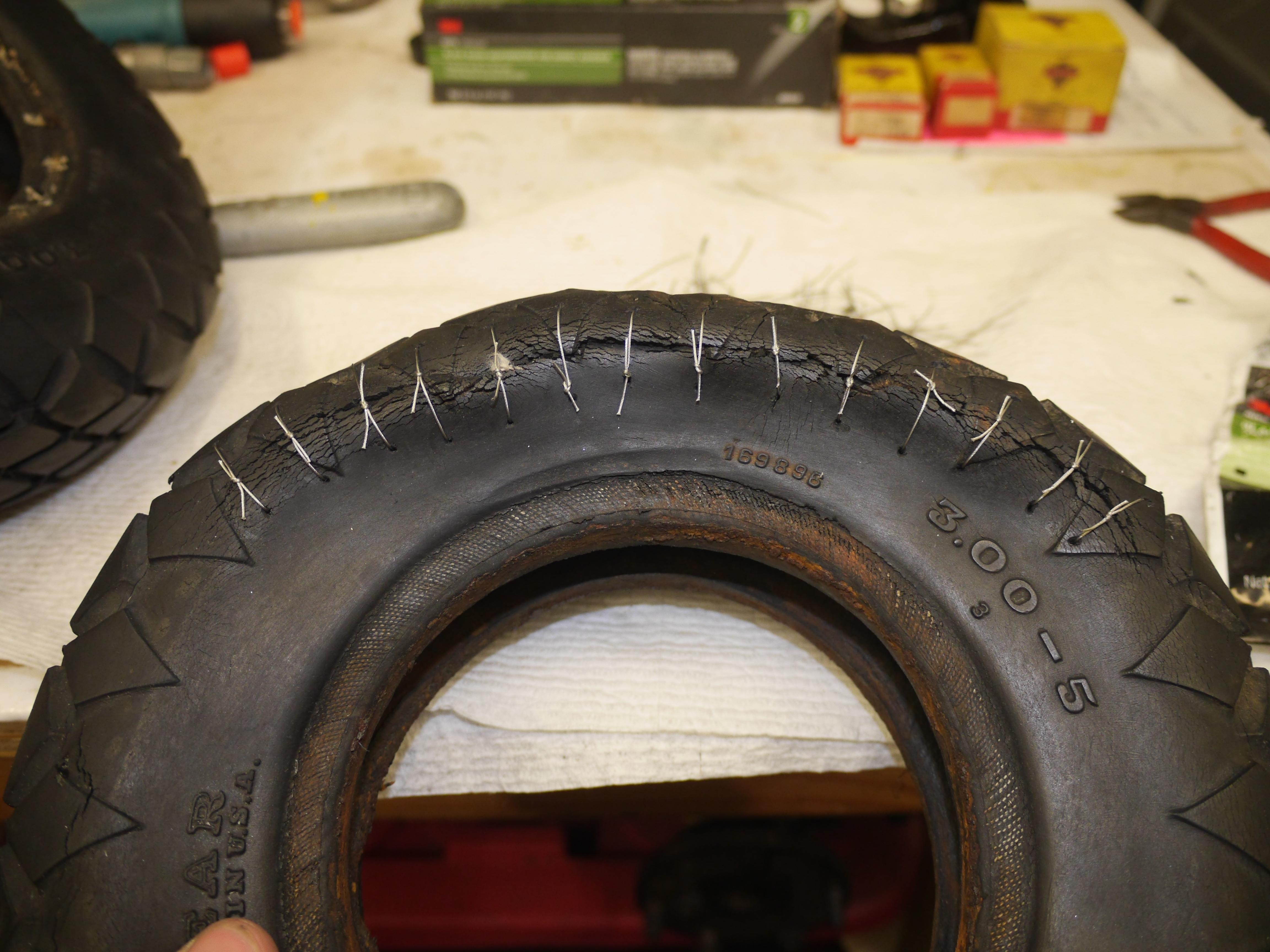
Now that the engine is all sorted out, I focused on repairing the original Goodyear 3.00-5 tires. I could replace them with a modern 4.10/3.50-5 tire, but nobody manufacturers a tire in this tread pattern in the United States anymore. It would be a crime to put a foreign tire on a machine entirely made in the USA. I decided that the only way to save the tires would be to stitch them back together. I have never heard of anyone doing this before, but I figured it was worth a shot. I did not really have much to loose by trying. I drilled small holes on either side of the cracks/tears in the sidewall of the tire, and stitched them back together with a 0.020" stainless steel braided wire. It took a long time to individually tie each sticth needed to weave the tires back together. All of the knots had to be tied on the outside of the tire so they would not puncture the inner tube.
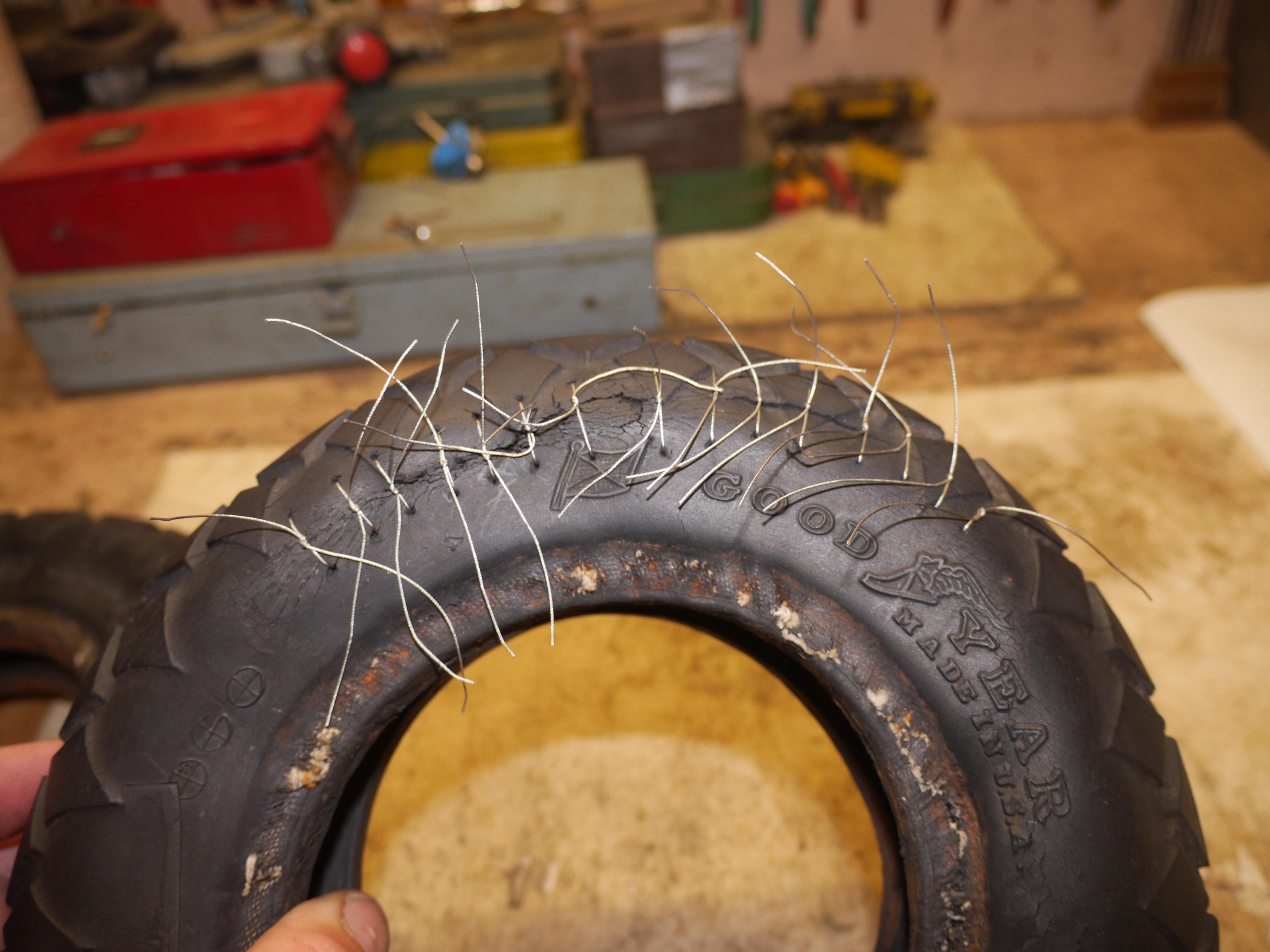
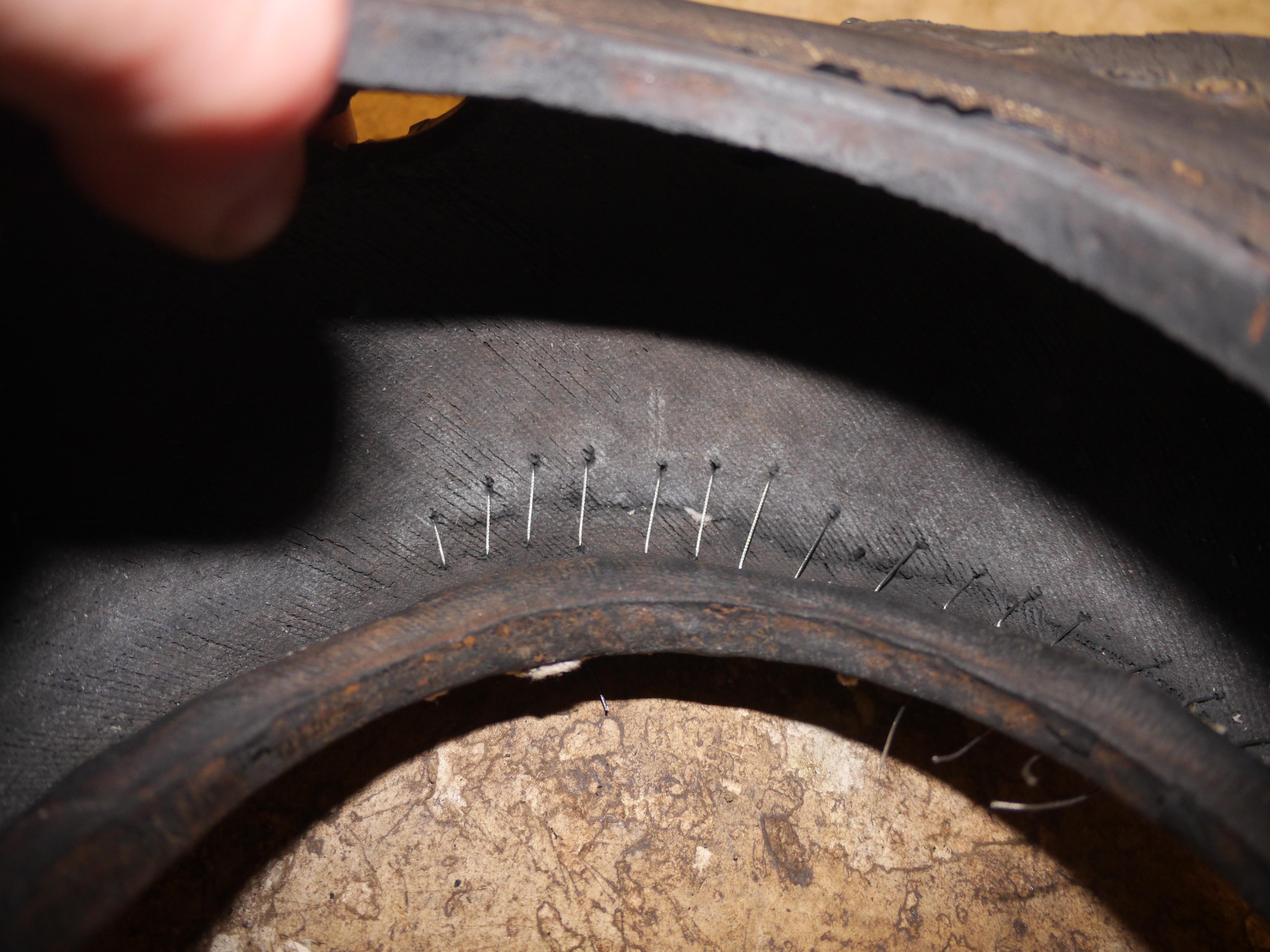
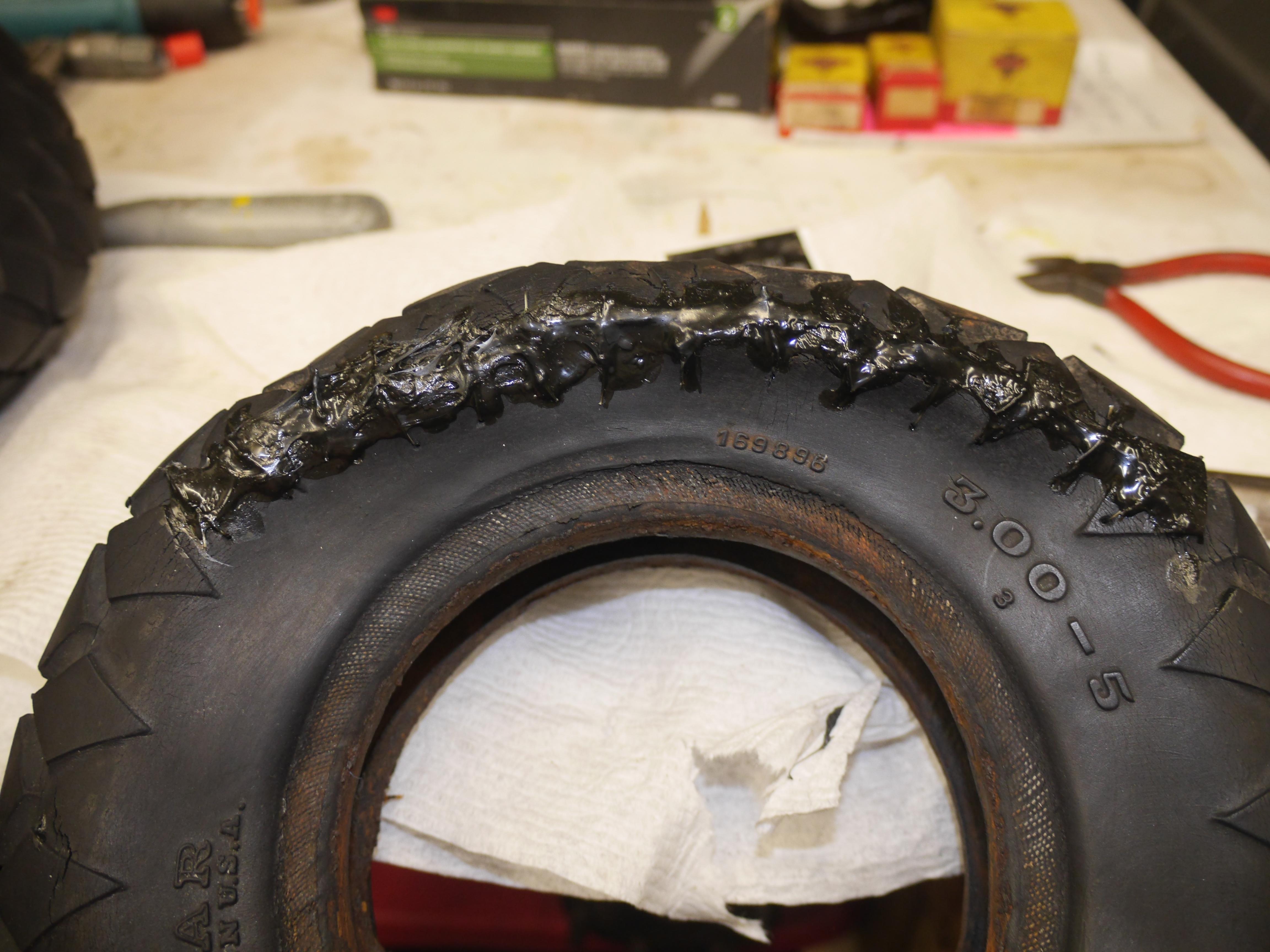
Several hundred holes and stitches later, both of the tires were stitched back together. In order to keep the stitches from coming out, I covered the repaired areas with 3M weatherstripping adhesive. I snipped the ends of the braided stainles steel wire back so that it woulc not catch or fray on anything when in motion.
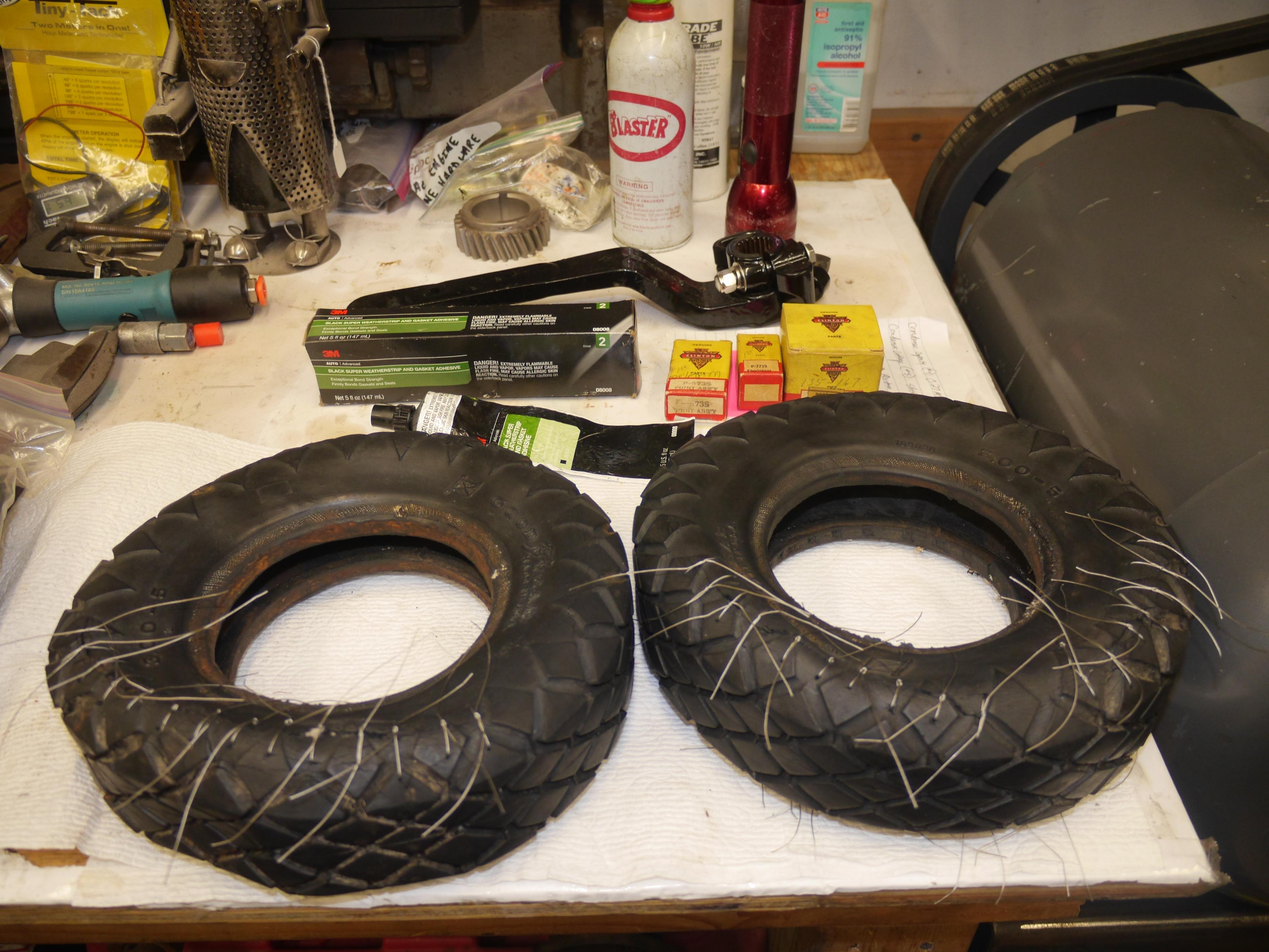
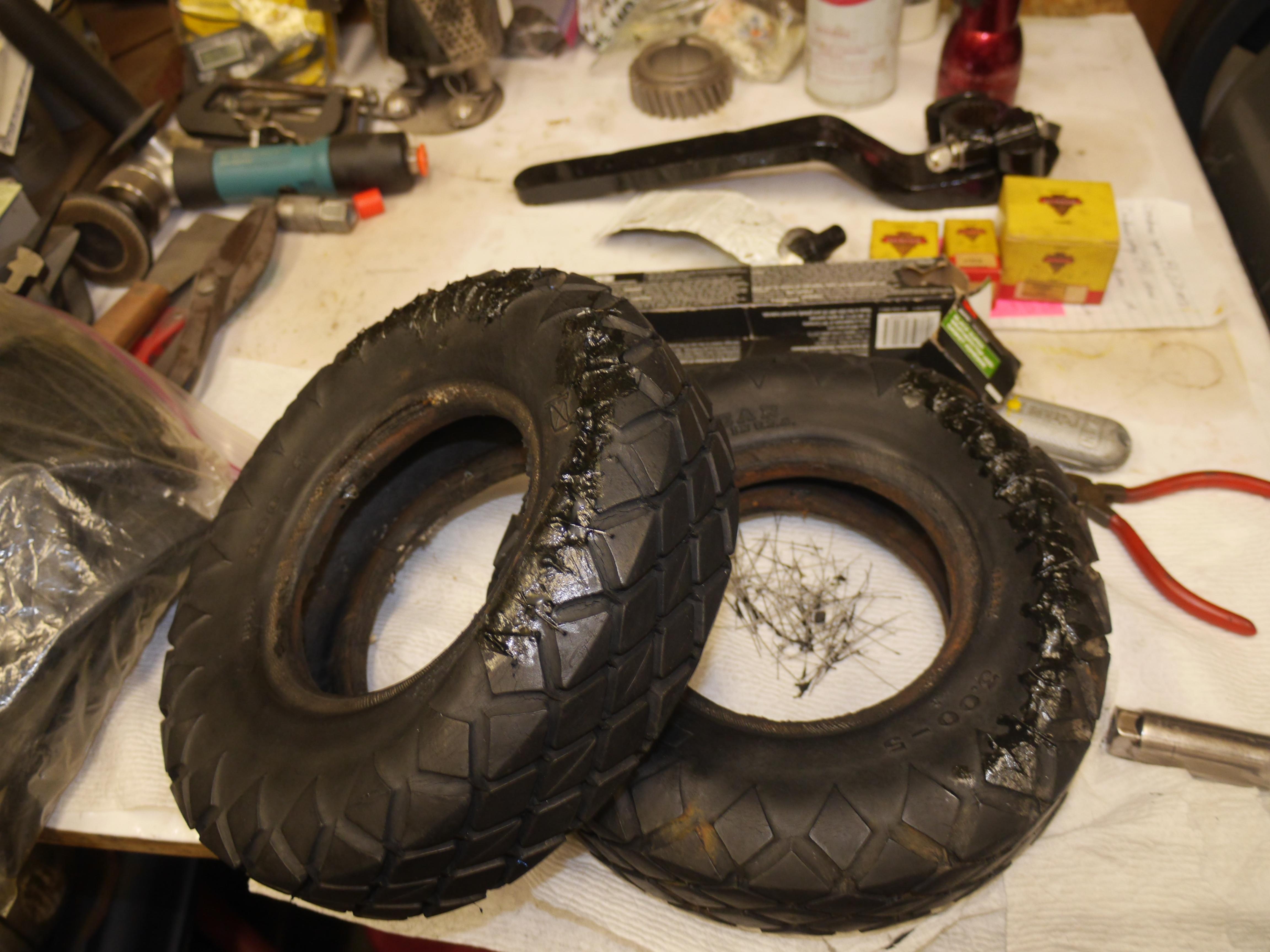
While I waited for the weatherstripping adhesive to cure, I spent some time cleaning the original Goodyear tubes. They were in sad shape, both had torn off stems. I ordered up some new tire tubes and proceeded to assemble the tires. Since the rims were in such bad shape, and there were no replacements available, I decided that I could vacuum form some PETG around the rims to prevent the tube from being cut on the razor sharp thin perforated rims. It took quite a bit of effort to line everything up for assembly, but I managed to squeeze the tube and the vacuum formed ring in place. I would not have been able to do this if this machine had one piece rims. Because these rims were dis-assembleable, I was able to line up everything on one side before attempting to line up the second half of the rim. After assembling both tires I cautiously aired the tires up for the first time in probably fifty years. Low and behold the tires aired up and held just fine. I was impressed.


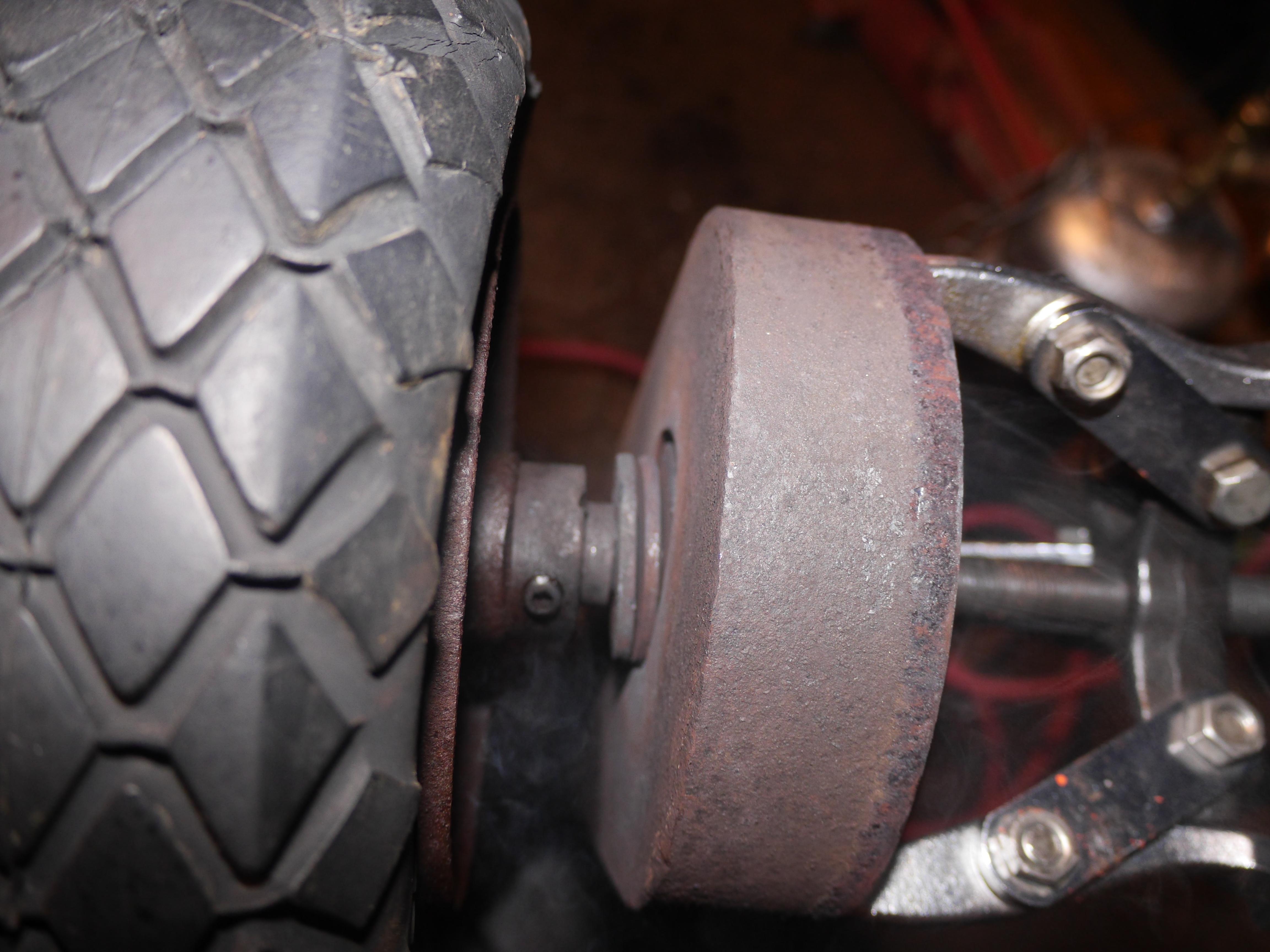
Before I installed the repaired wheels on the axle I made sure to cover the axle with anti-seize. I slipped the passenger side drive wheel in place and locked it to the axle with a key and a locking collar. Installing the driver side wheel was just as straight forward.
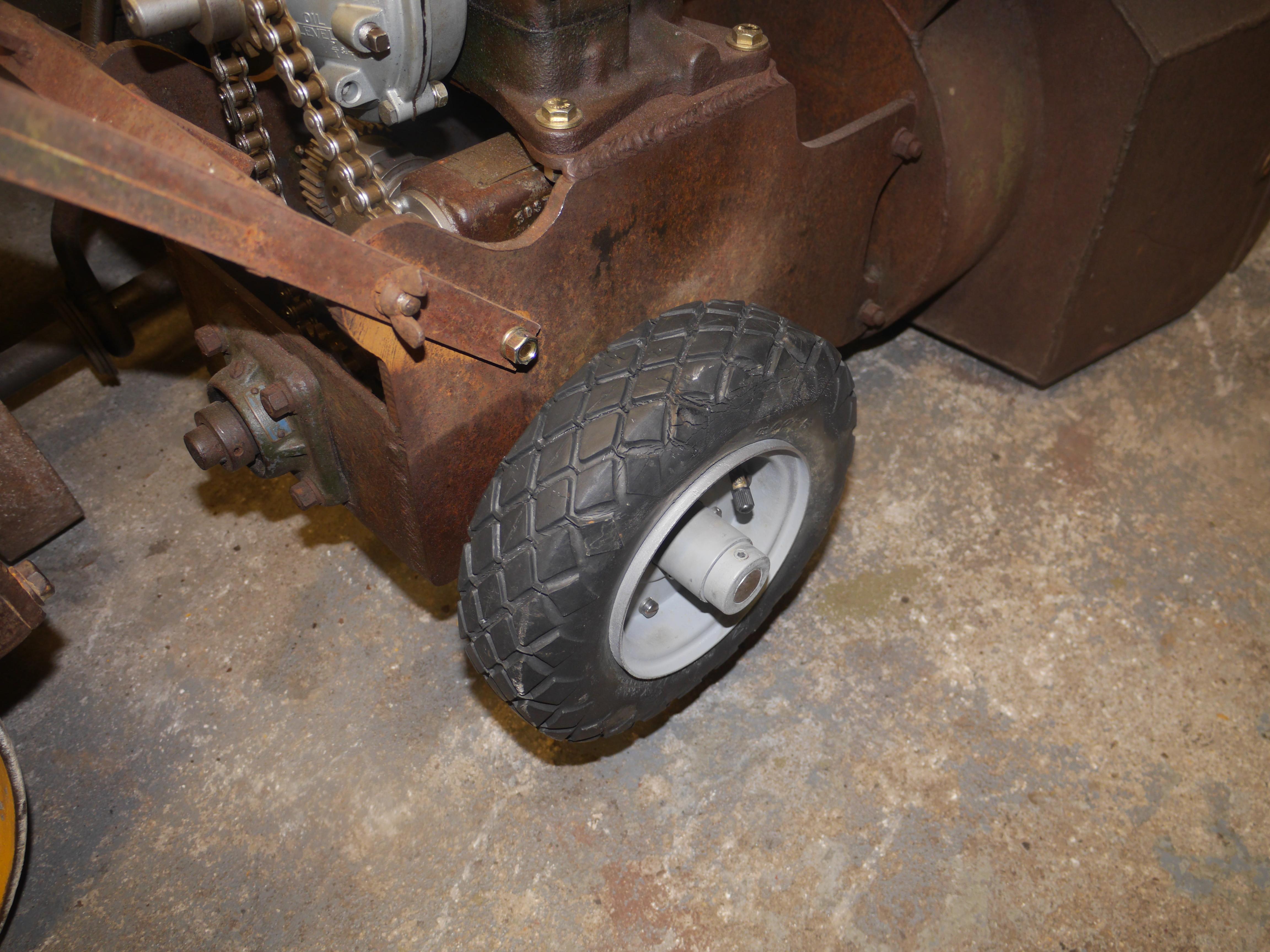

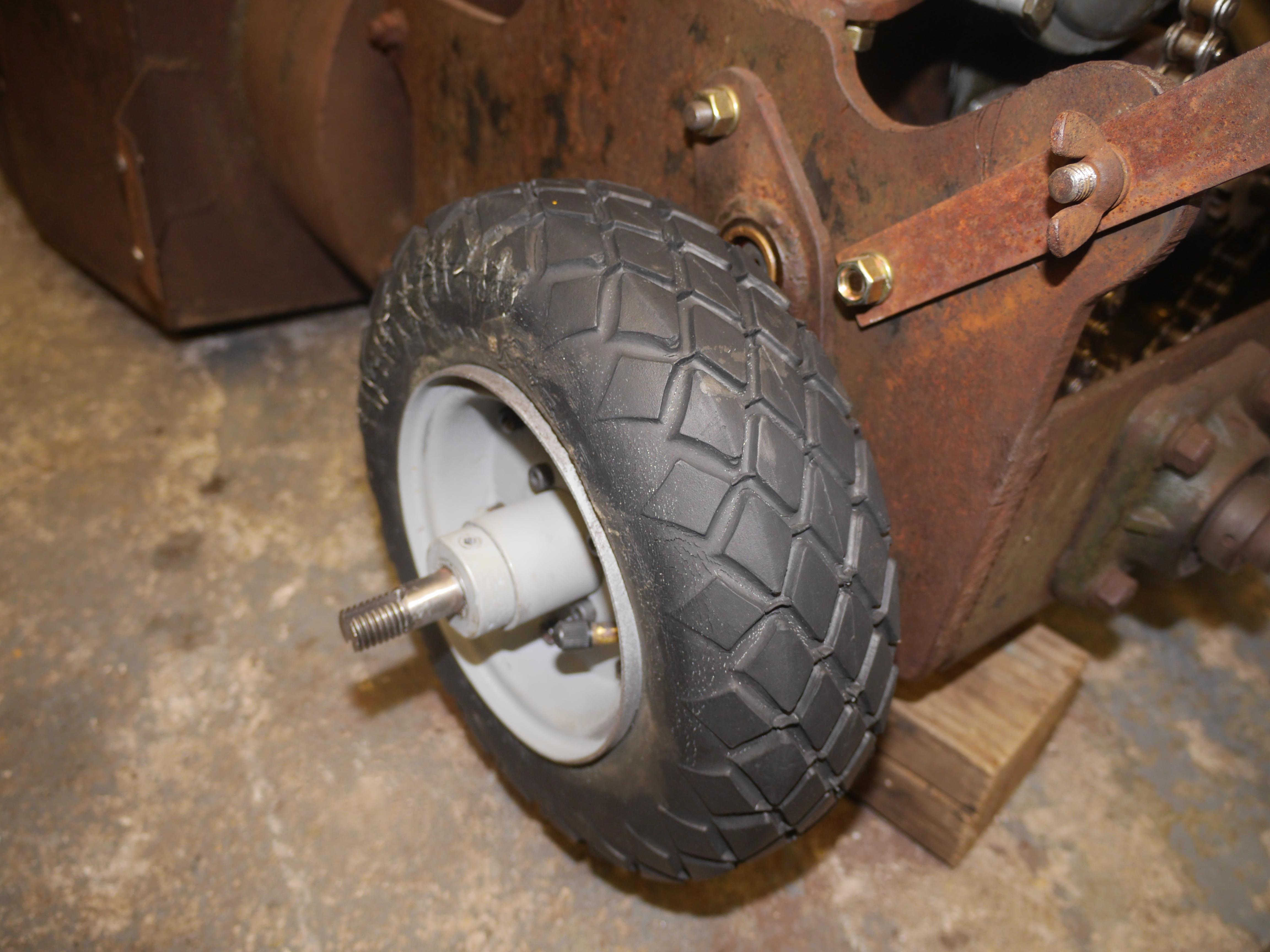
After installing the driver side wheel, I installed the appropriate washers and the chain guard. When it came time to install the auger drive sprocket I made sure to use more anti-seize to prevent the sprocket from rust welding to the shaft again. I installed the ultrasonically cleaned original Pratt & Whitney roller chain and fitted a new master connecting link as the original was just a piece of tie wire.


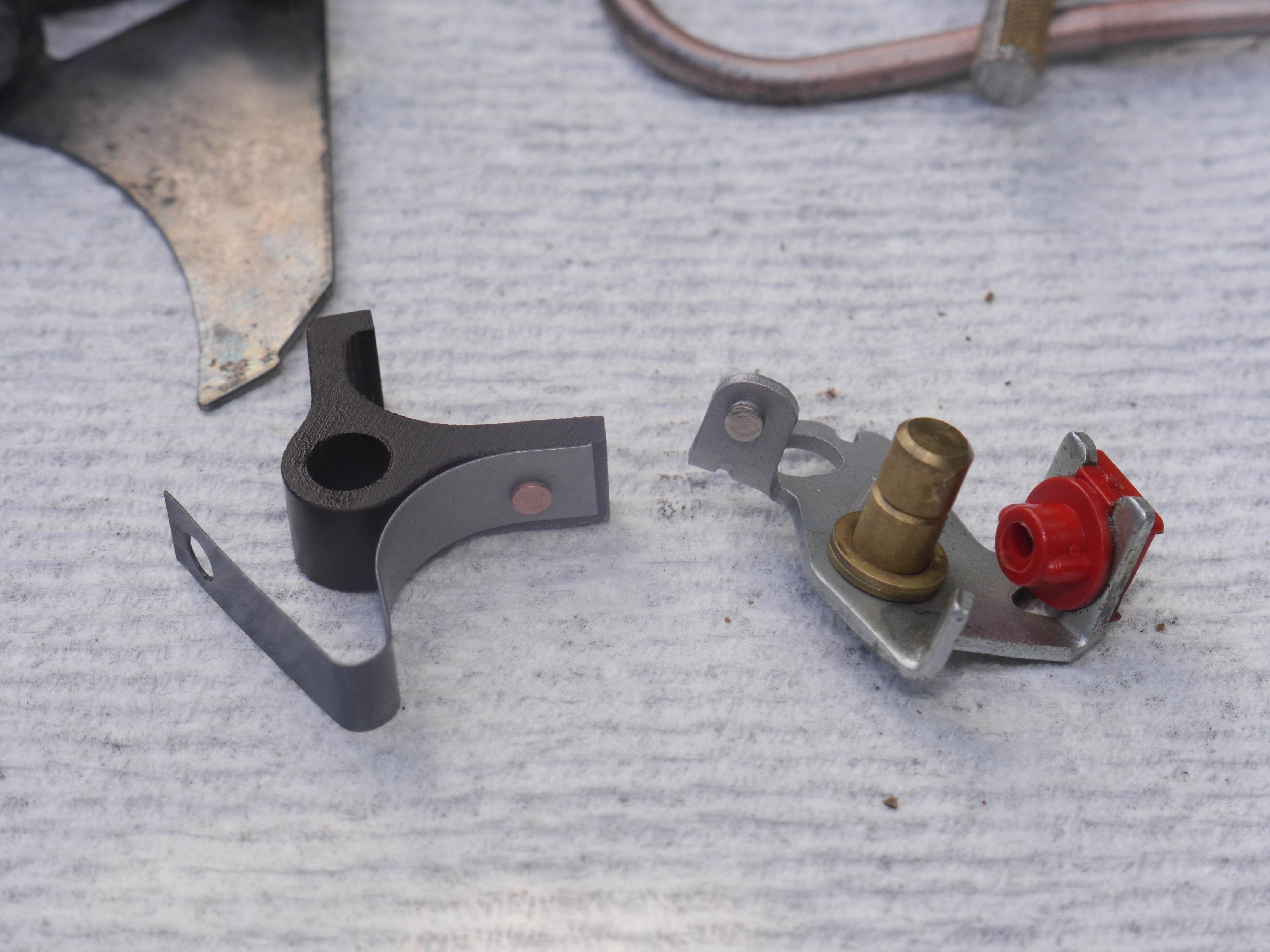
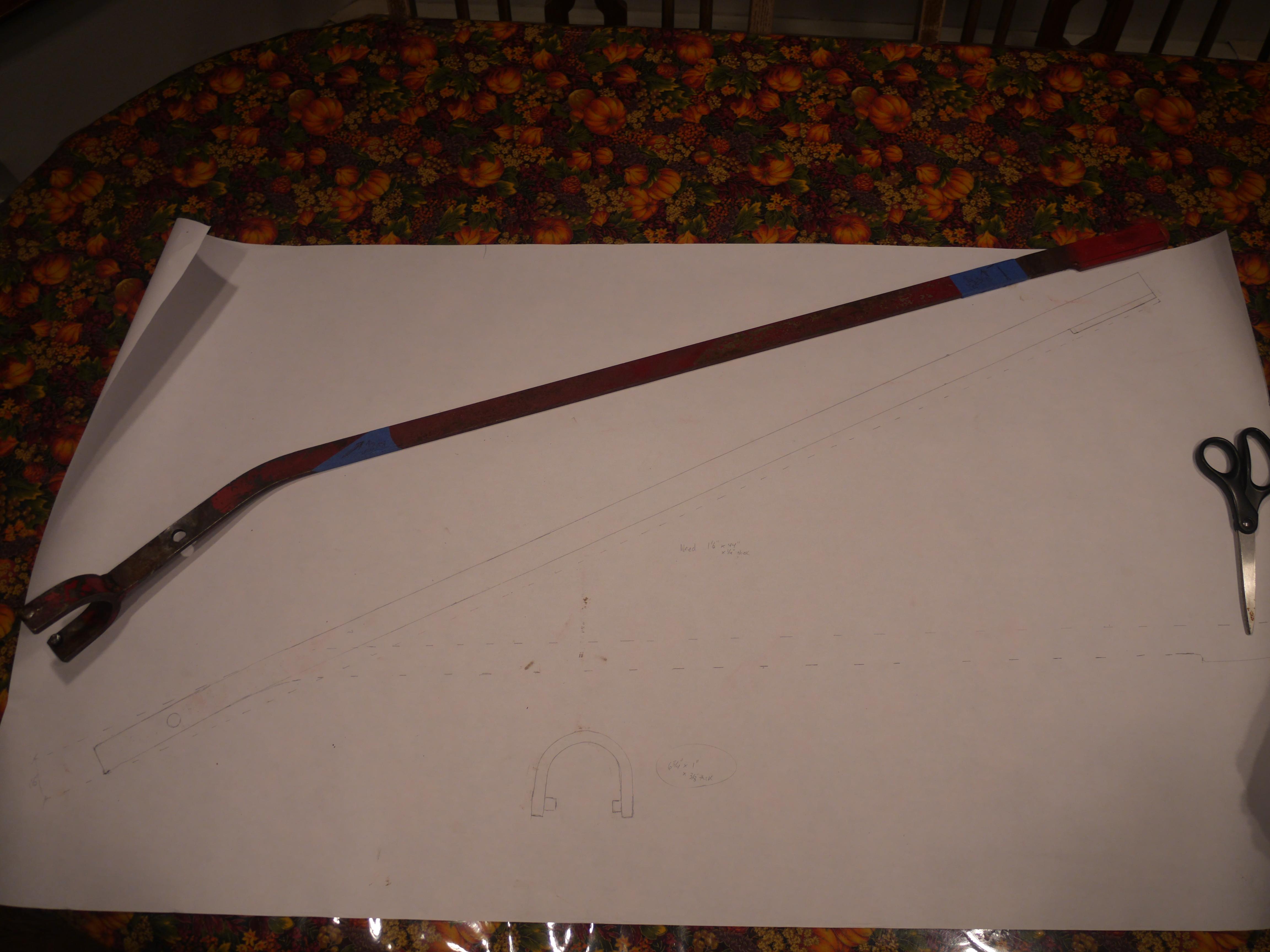
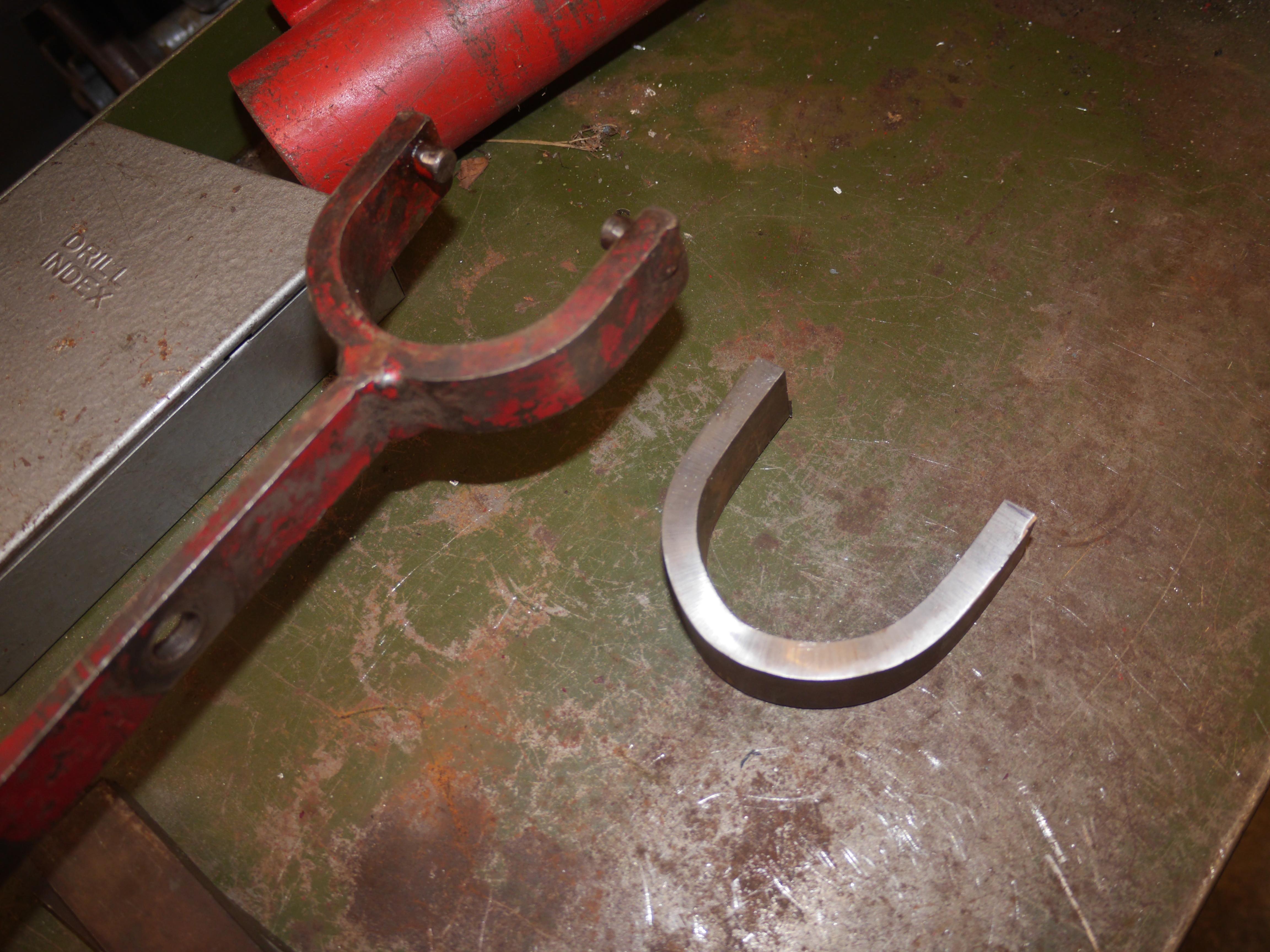
Now that the engine and tires are all sorted out, I focused on making a new clutch fork and clutch lever for my snow thrower. I took my 1952 Maxim Silencer model 4-19 out and compared the two side by side. Both machines use the same Boston Reductor worm drive transmission, so the clutch and clutch for should be very similar. I removed the clutch lever from my 4-19 and bolted it in place on my 2-19 snow thrower. I immediately noticed that the clutch levers are not at all interchangeable. I grabbed an old cutting edge for a snow plow, as it was the only piece of steel handy that would fit in the original Maxim handlebar channel that could be temporarily connected to the Maxim 4-19 clutch lever. It turns out that the clutch fork is the same, just the design and curvature of the lever differs. As you can see in the pictures, the new lever needs to be just about straight.

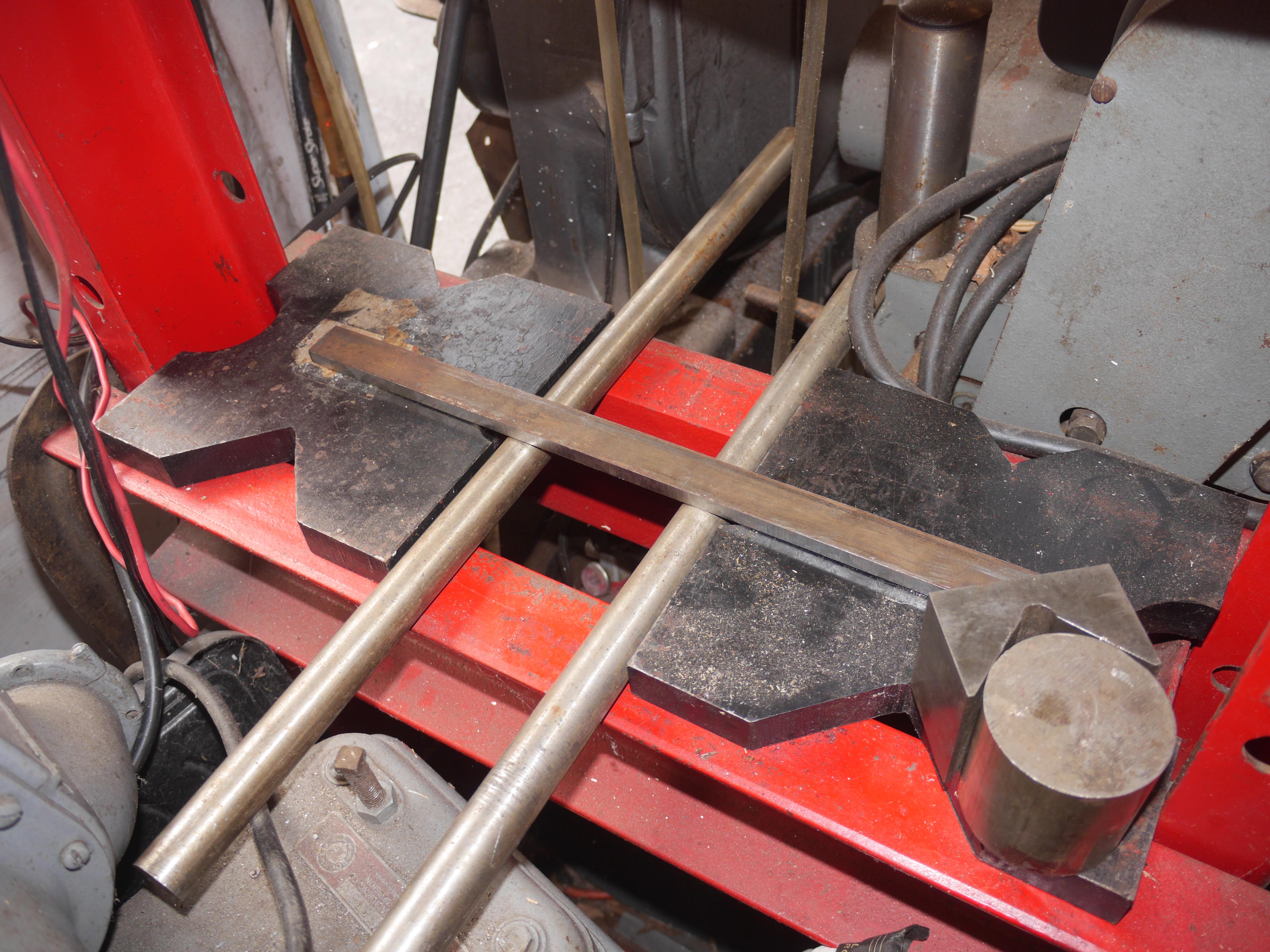
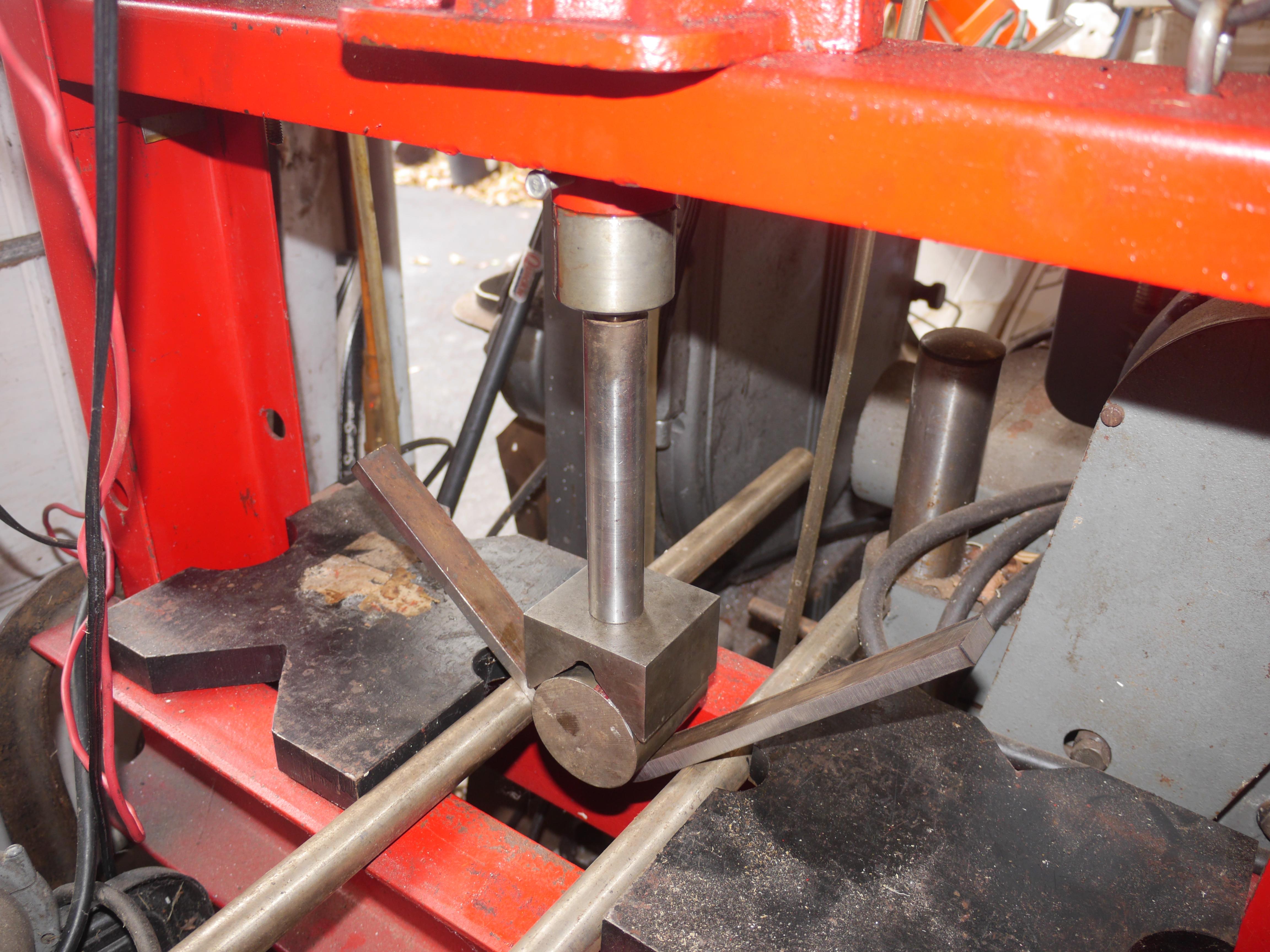
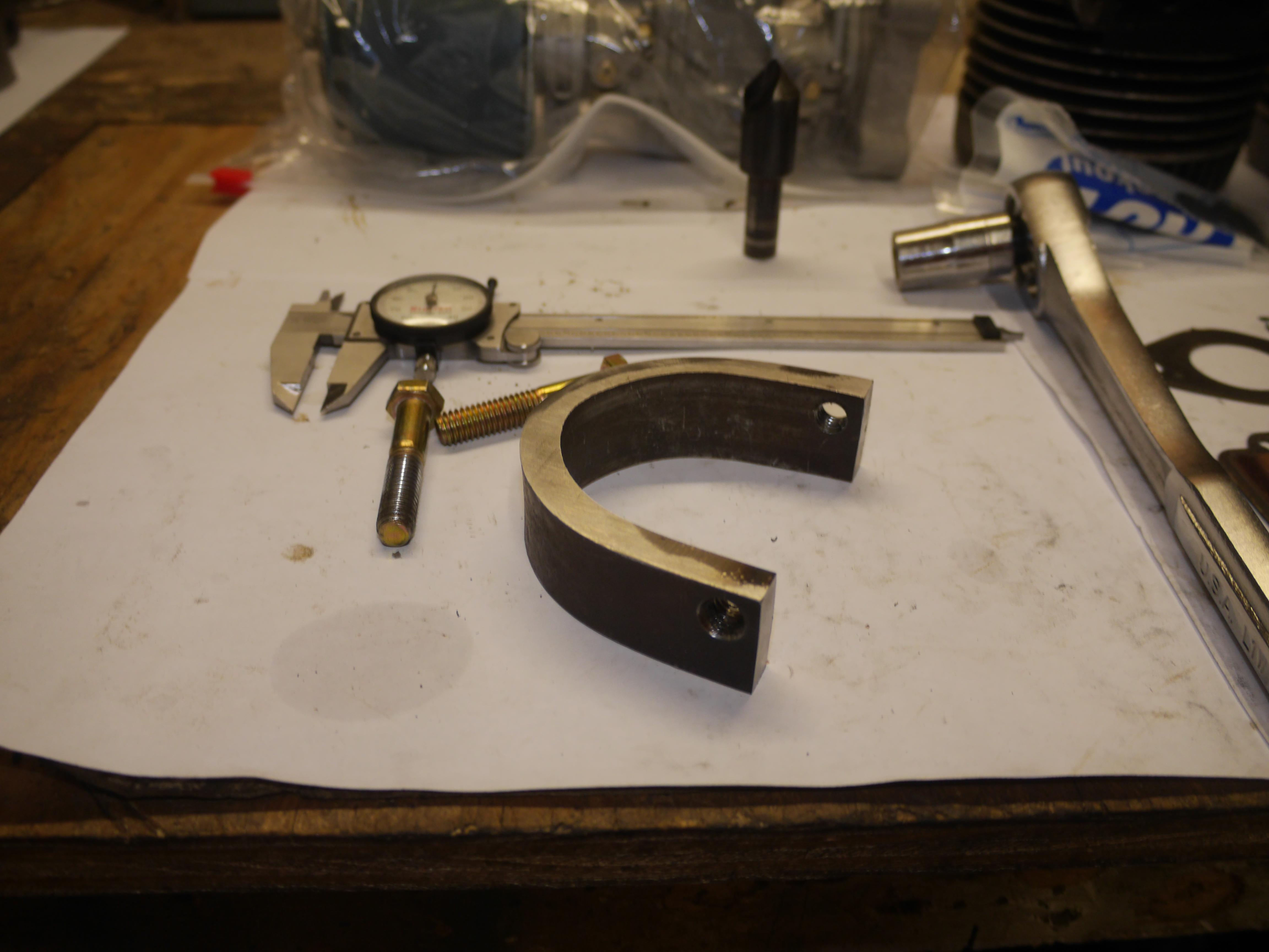
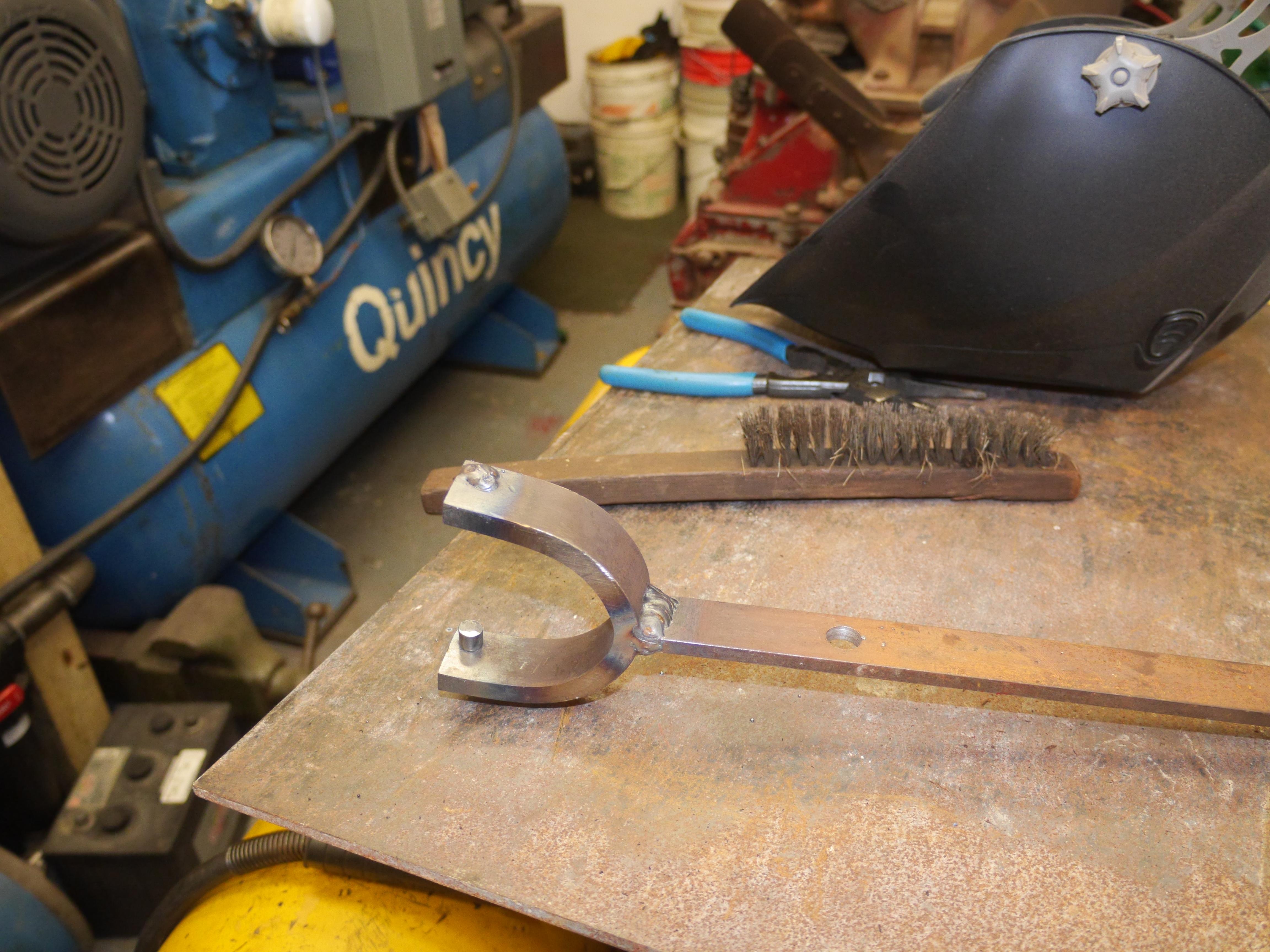
After taking several measurements I drew the Maxim 4-19 clutch lever out on a piece of paper at 1:1 scale, and drew what I thought the clutch lever for the Maxim 2-19 should look like. I started out with a piece of 3/8" plate steel 1" thick. I put two rollers down on the platform of my 20 ton press. With a 2-1/4" piece of round stock centered on the piece of 3/8" plate steel and a big vee block ontop of it, I used my 20 ton press to shape the new clutch yoke. Surpringly the press was able to bend this thick steel without too much trouble.
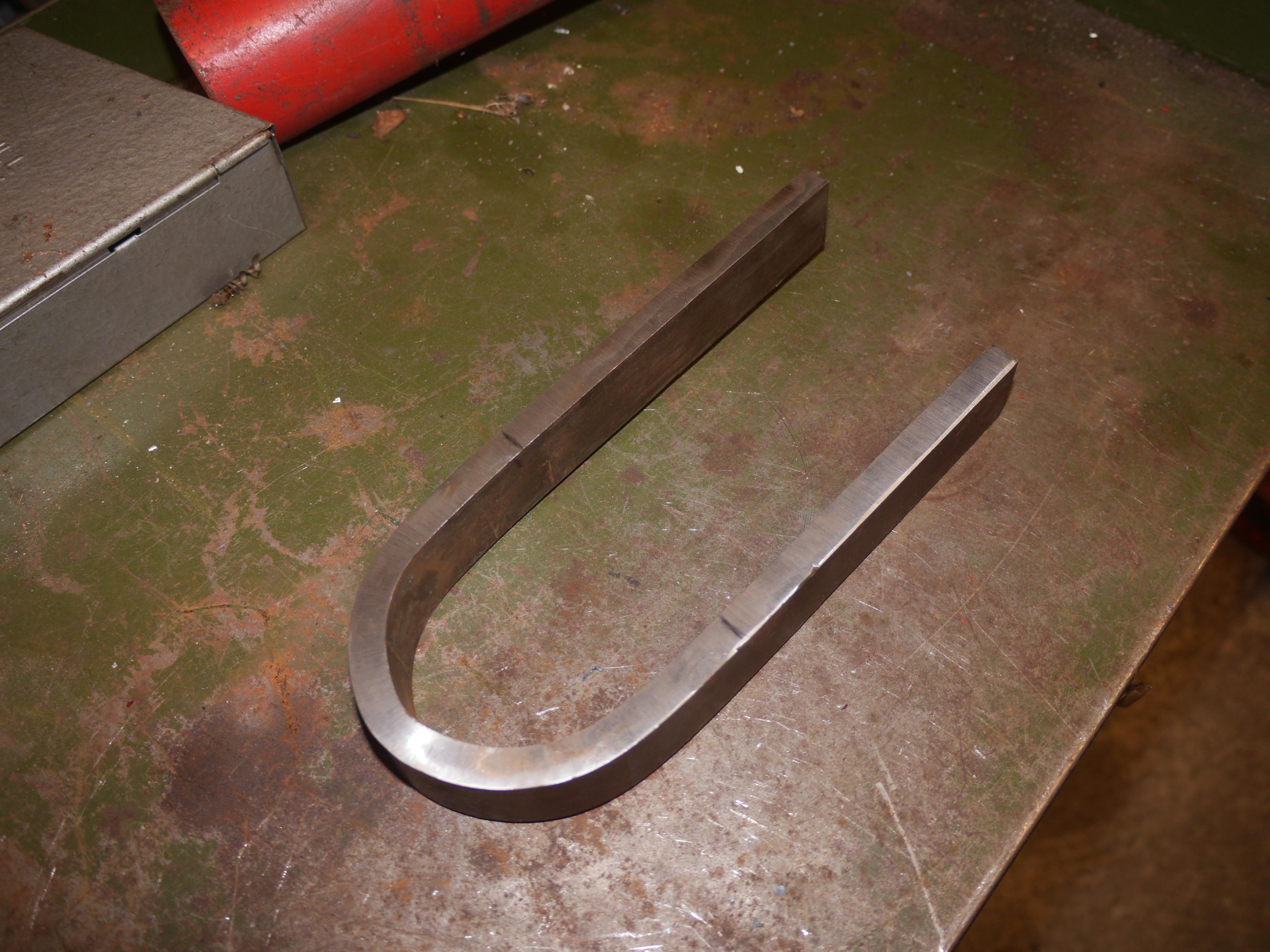
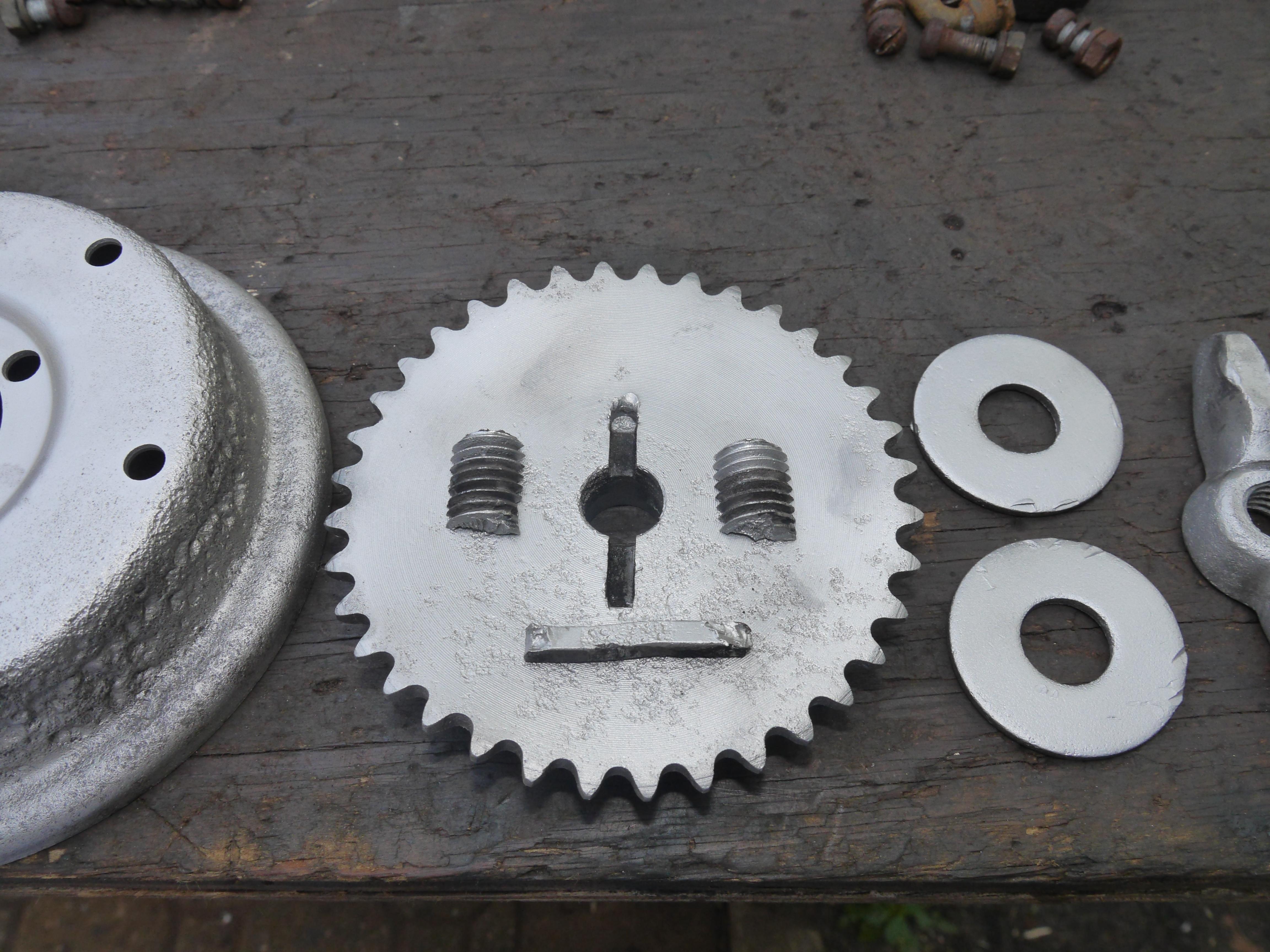
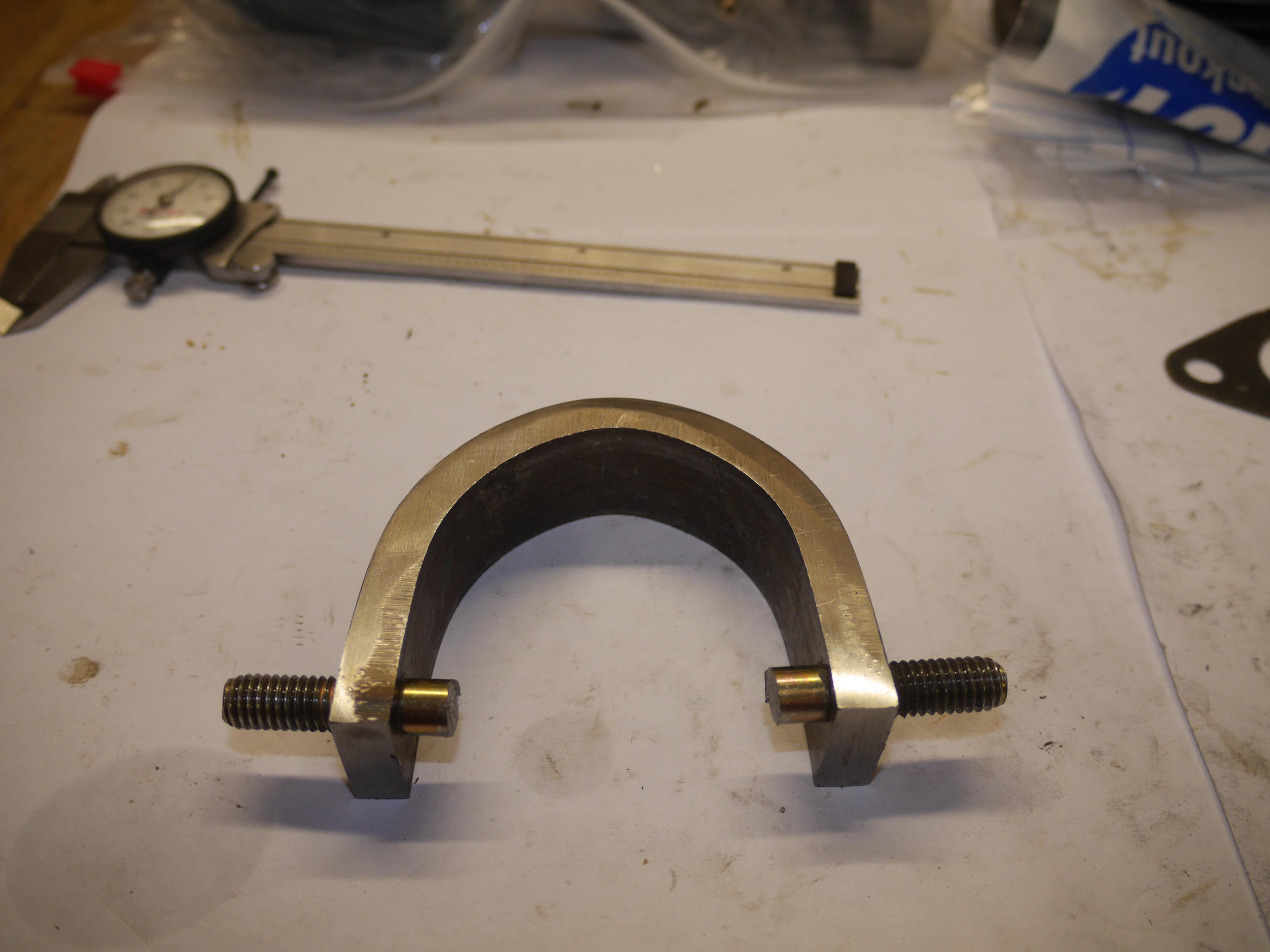
After cutting the new clutch yoke to size, I decided to drill and tap the new clutch yoke to accept a pair of 3/8-16 bolts. I will use the straight cut shank of these bolts as the pins which slide the clutch back and forth. After threading these two bolts in place, I cut the heads of the bolts off and cut the extended threaded ends of the bolts off to match the original clutch yoke. I think the new clutch yoke is pretty much a perfect duplicate! I just need to weld the two threaded bolt ends to the yoke like the original.

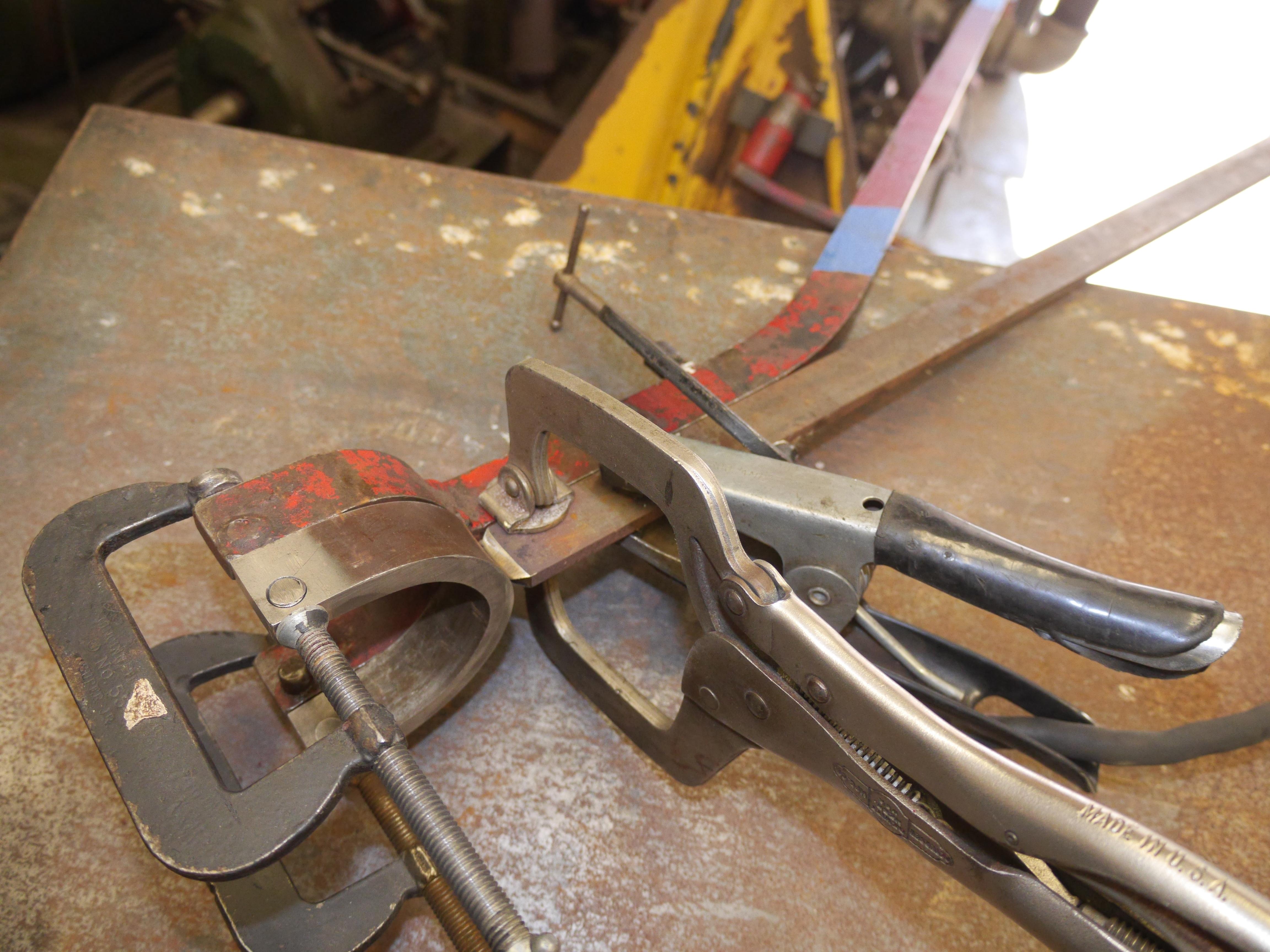
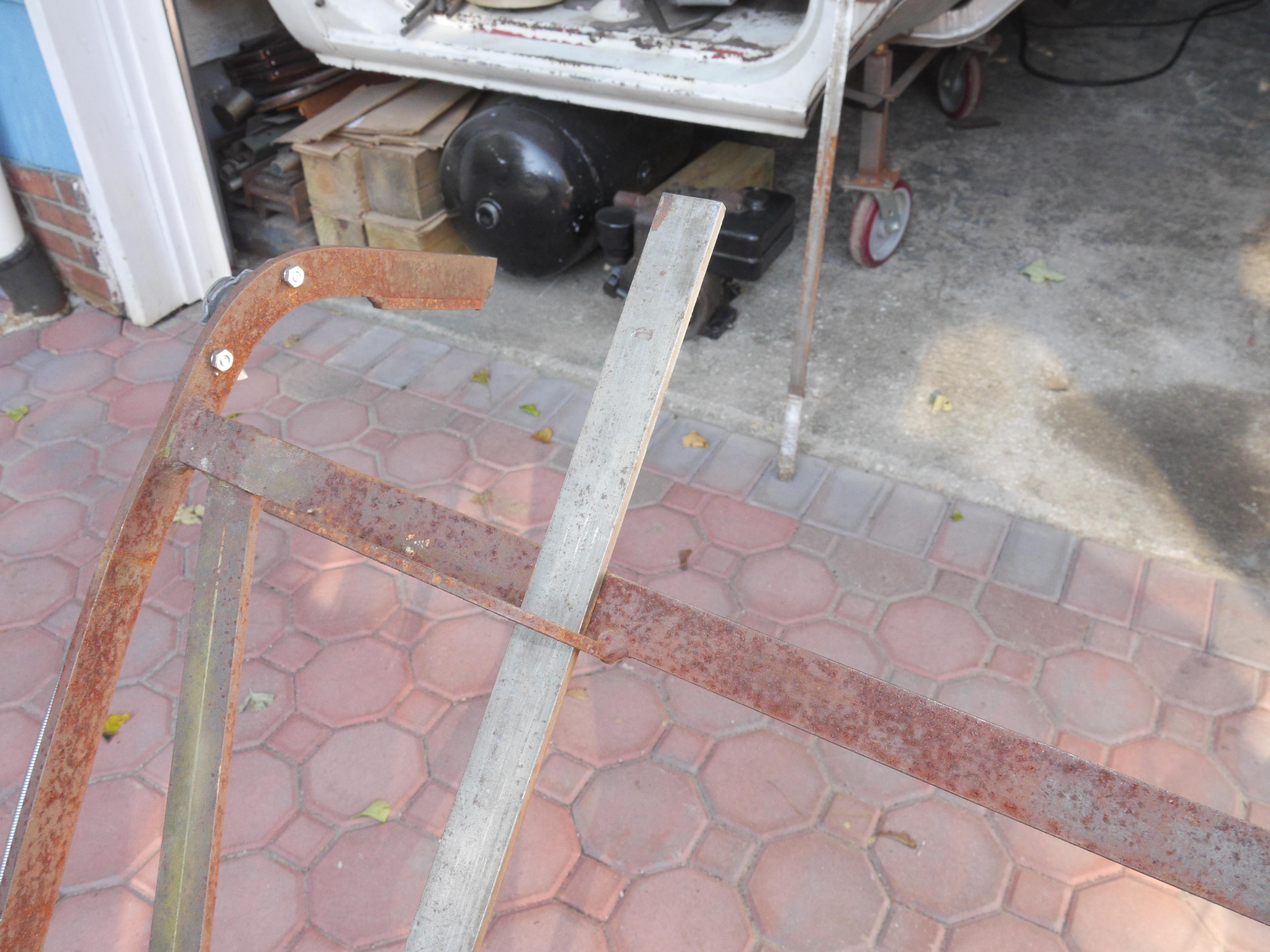
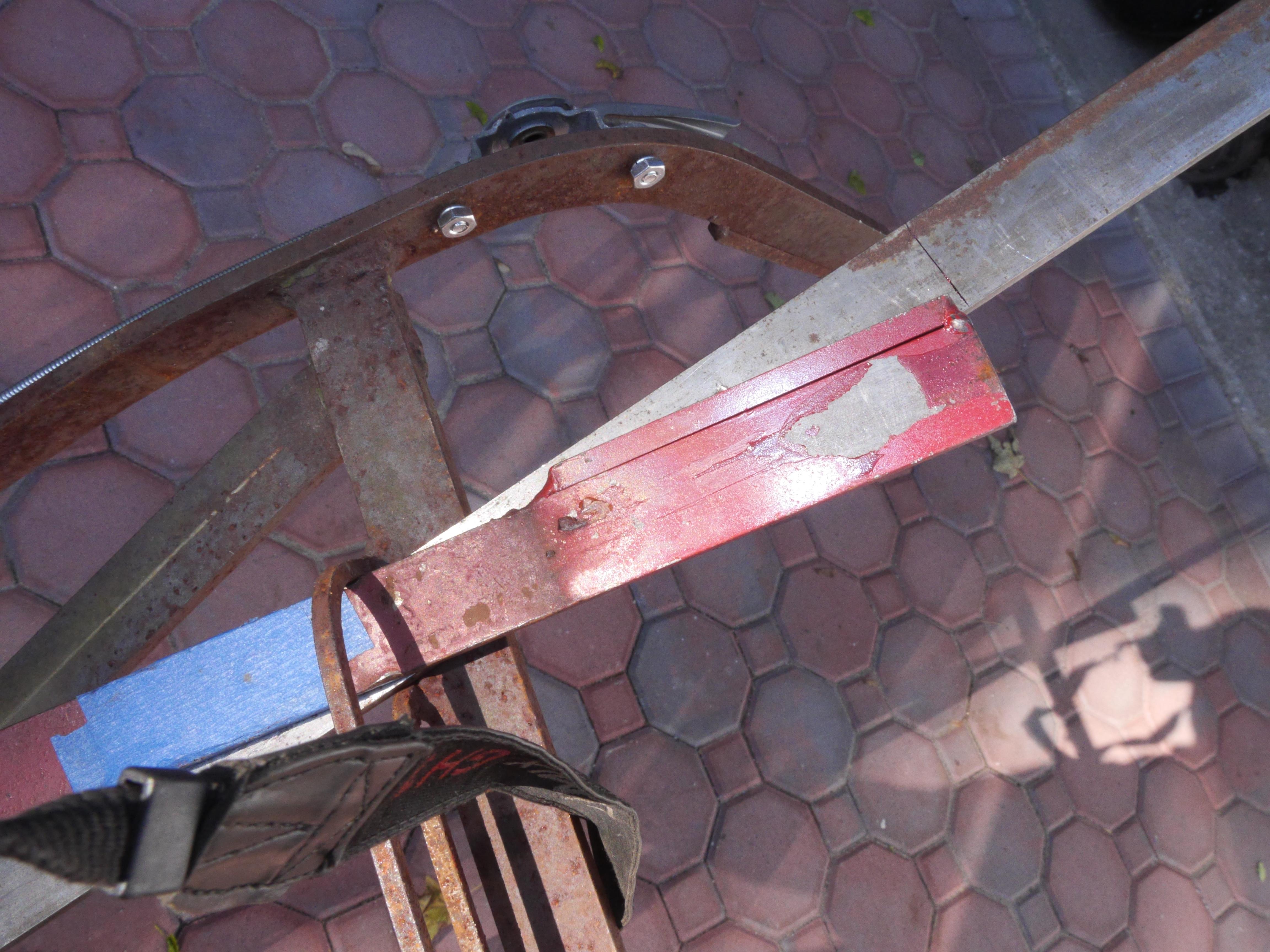
I picked up a nice old length of 1/4" plate steel 1" wide from my stock pile and began making the new clutch lever. In order to get the angle just right, I clamped the newly bent clutch yoke to the original one I had. I tack welded the new lever in two locations and then proceeded to see how it would fit on my machine. I measured the location of the pivot point and drilled an appropriately sized hole. I bolted the new lever in place and tested how it worked.

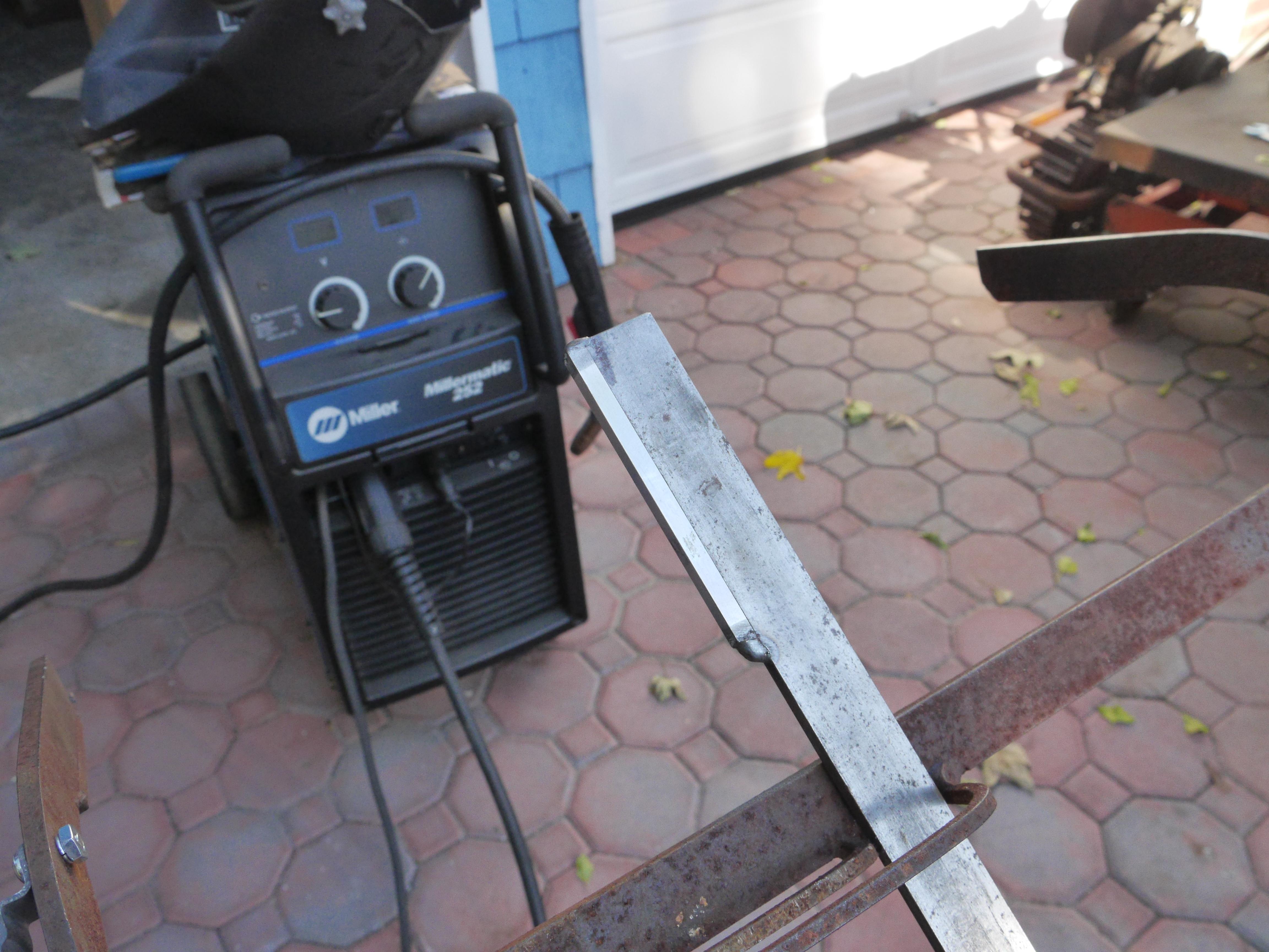
The new clutch lever seemed to work just fine moving the sliding clutch back and forth, so I took the lever back out of the machine and proceeded to finish weld it to the yoke. I took this opportunity to weld up the two threaded pins in a similar fashion to the original clutch lever. When re-installed I simply had to cut the lever to length.
With the lever cut to length, the last step was the welding in place of a small section of 1/4" key stock. The original clutch lever is setup this way so that the same rubber grips can be used on both the handlebars and the clutch lever.

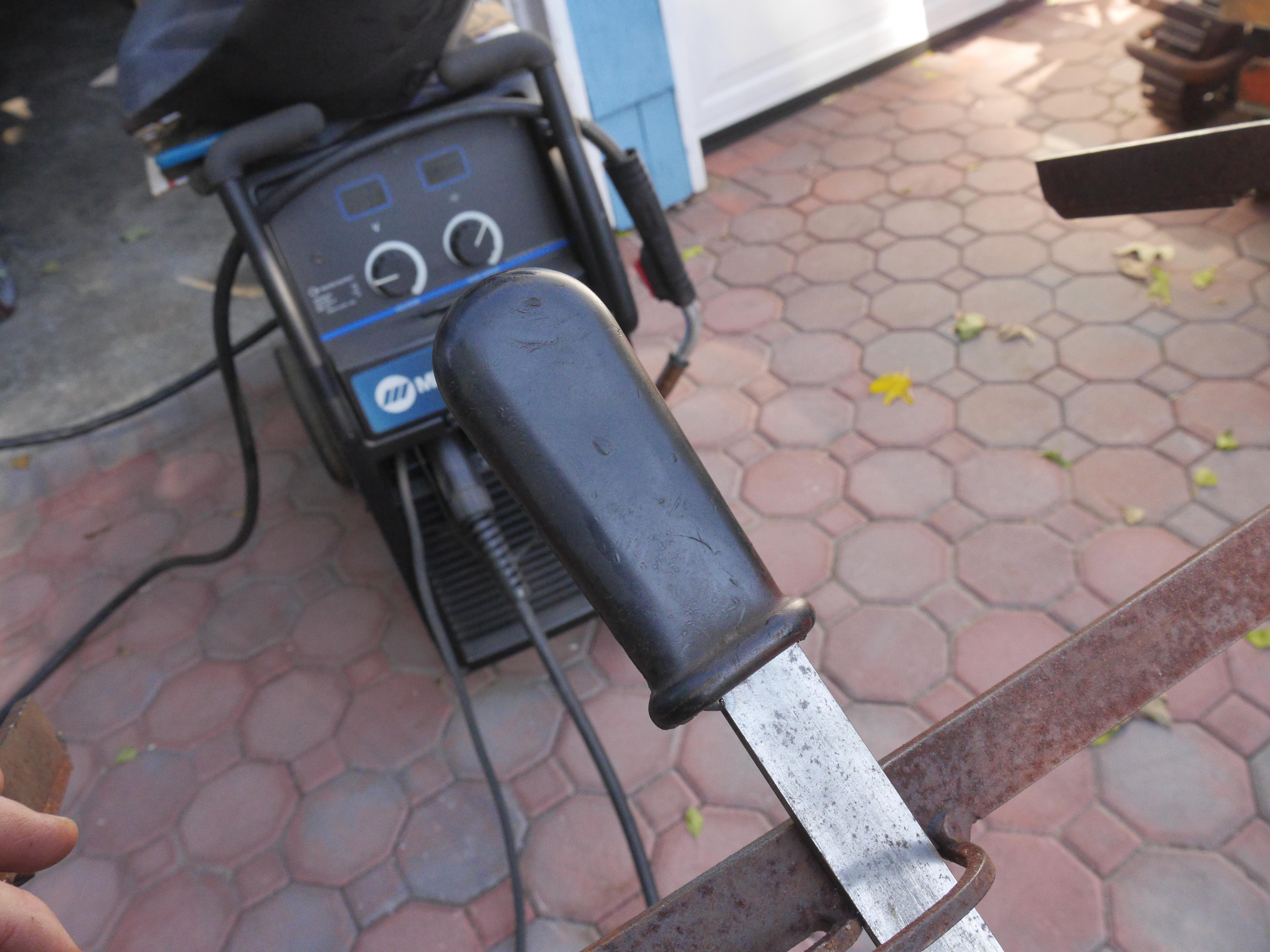
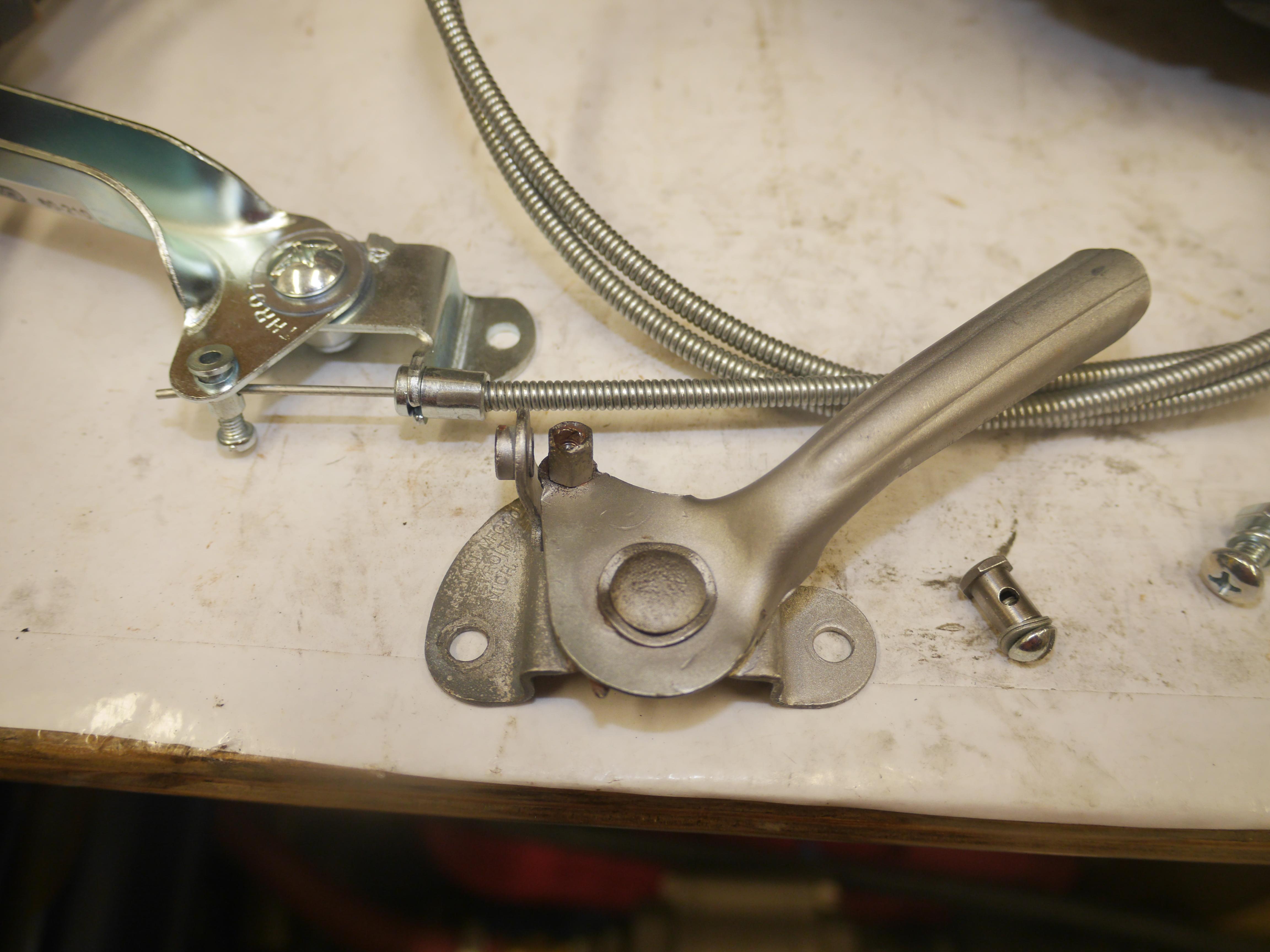
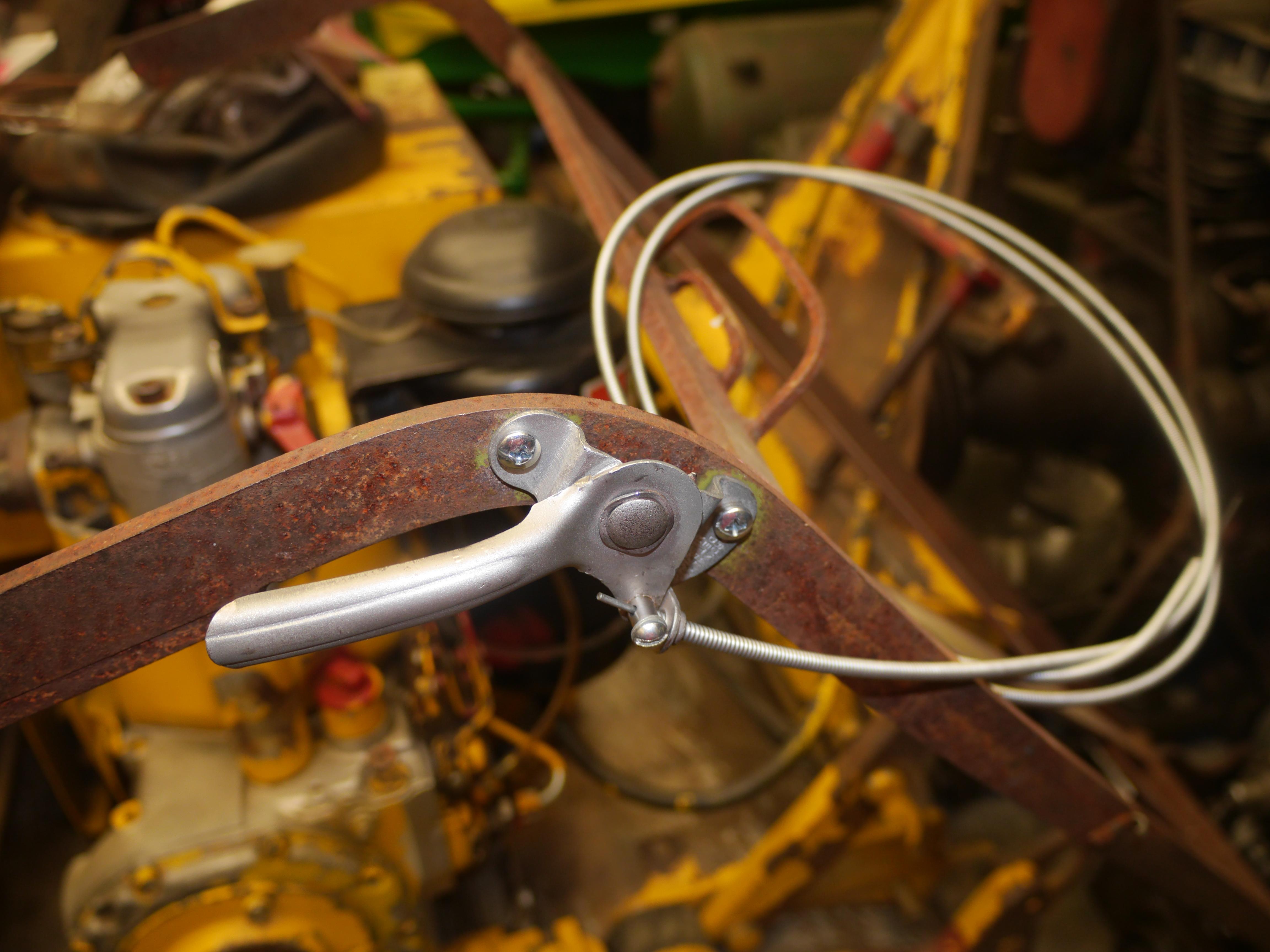
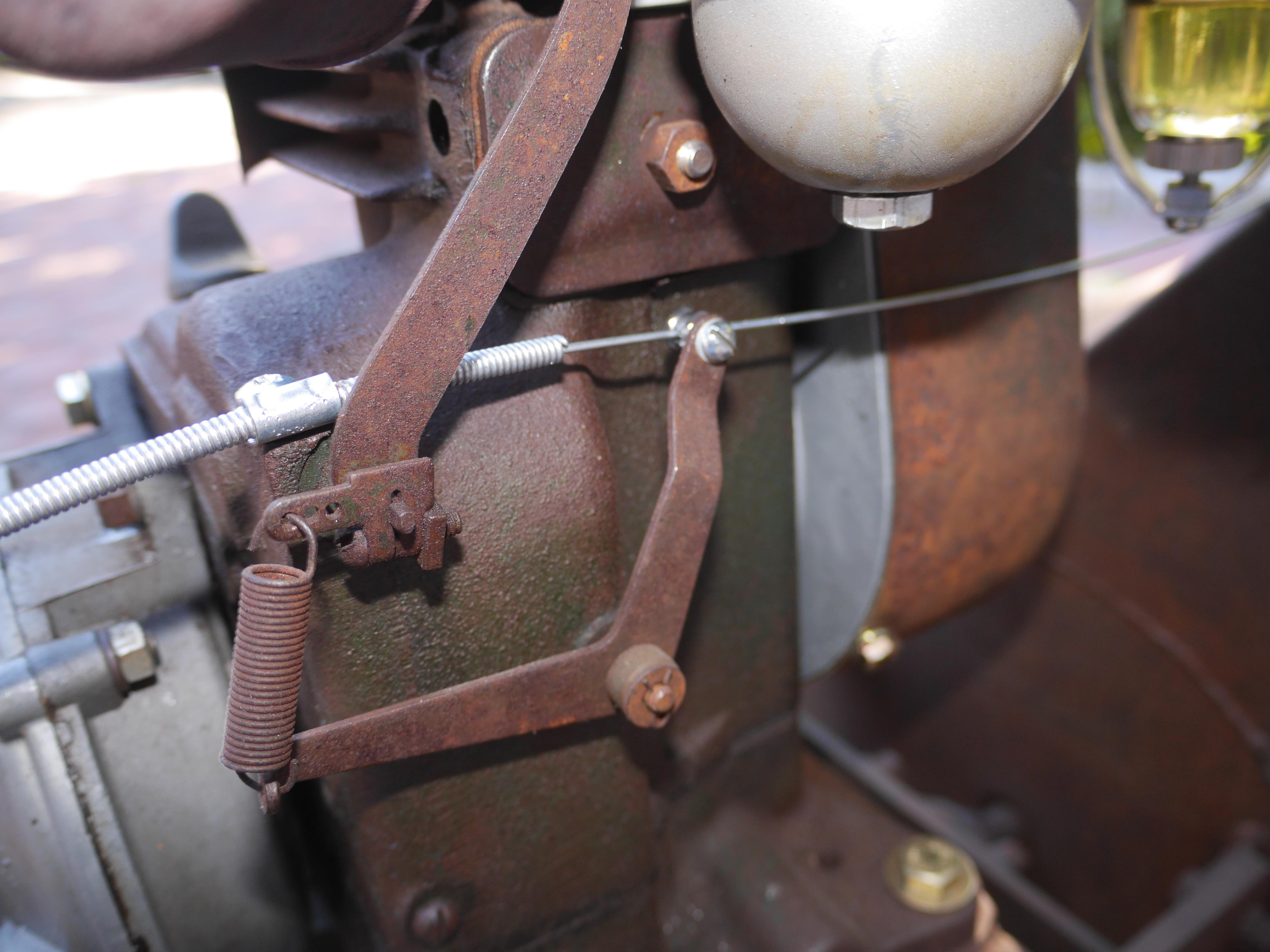
Now that the clutch lever is complete, there is only a short list of items to repair; namely the throttle cable and the air cleaner. The original throttle cable is a Cardinal brand made in Detroit, Michigan. I really liked the original style throttle cable, so I cut off the old rusted cable, and swapped over the cable from a new throttle cable. I had to drill out the original locking tab, so I mounted a new barrel lock in its place. The new cable threaded into the old lever just fine. I made up a few steel cable clamps and finished mounting the cable to the governor on the engine.

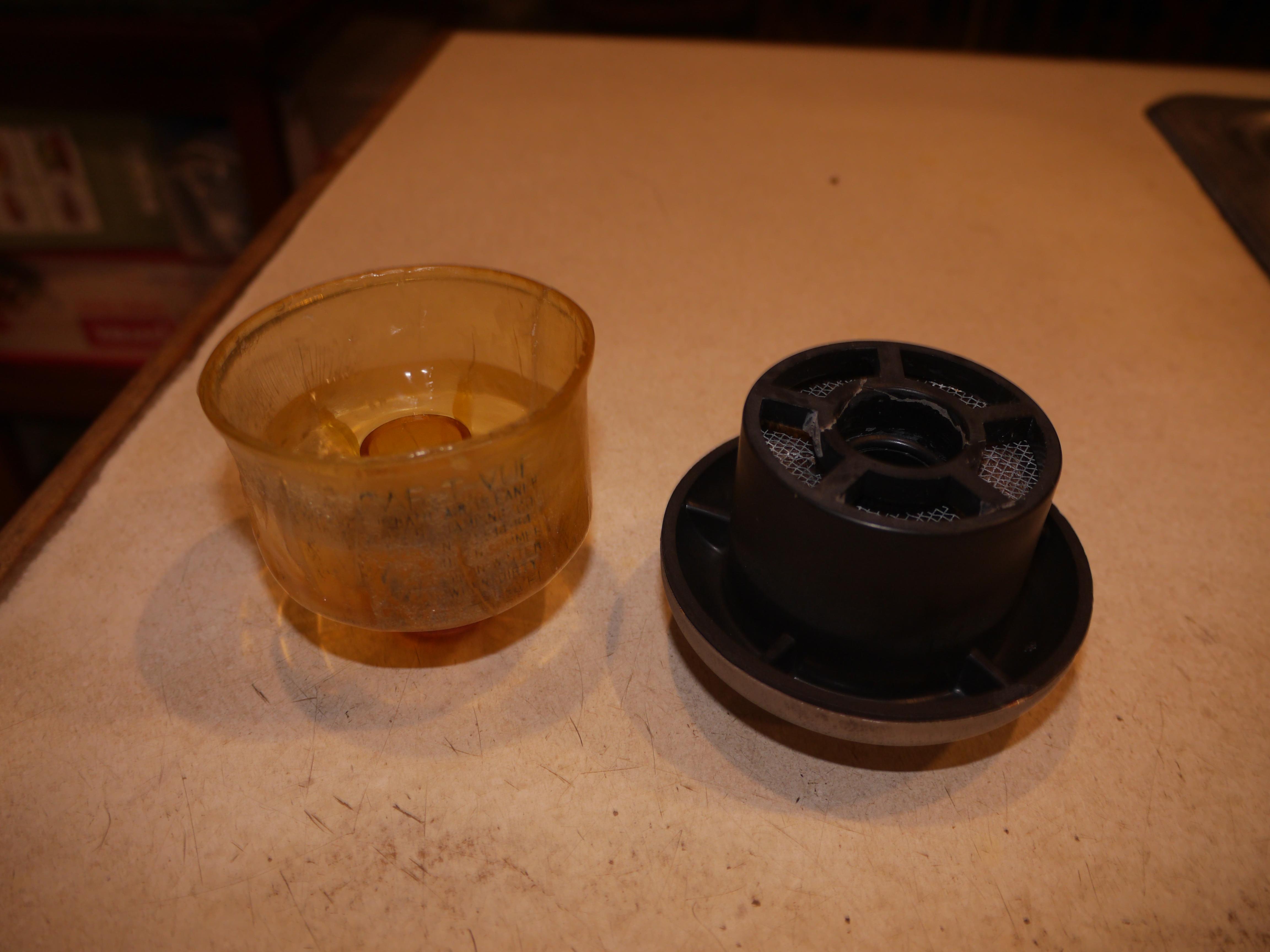
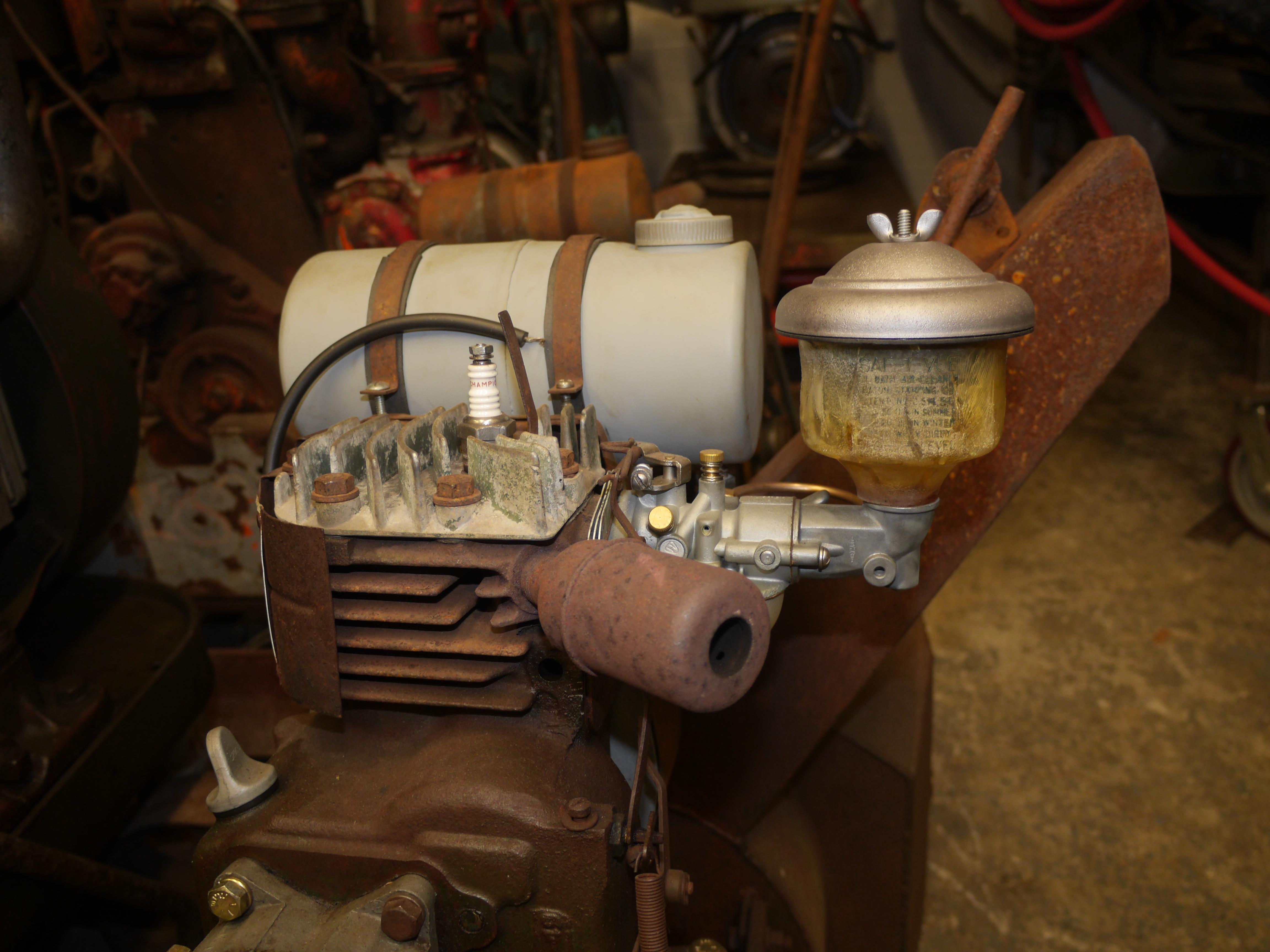
The last step was basically to hunt down a correct air cleaner for my engine. Clinton used several different air cleaners on the B700 series of engines, but since mine had an up turned cast aluminum elbow bolted to the throat of the carburetor, I believe it originally had an Eaton Saf-T-Vue clear oil bath air cleaner. Of course there were none available when I needed one, so I ended up buying a complete other engine for the air cleaner. The other engine arrived safe and sound, but it was in awful shape, much worse than the engine that came on this snow thrower. The Saf-T-Vue air cleaner actually arrived unscathed, but due to the lack of room here, I bumped into the engine and it toppled off of the table. I grabbed the engine by the fuel tank, and when I did the fuel tank broke off the engine and low and behold the only part which hit the ground when I caught the engine was the air cleaner. The one piece I really needed broke! I was so annoyed. I ended up using a two part clear epoxy to glue the air cleaner back together. It looks pretty bad, but it almost looks right on the machine. Its just rough and beat enough to fit the look of the rest of the machine.


The machine is now complete, it is November 3rd of 2018, just two months after the acquisition of the Maxim 2-19 snowthrower and I am pleased to announce that it runs, drives and works like it should.
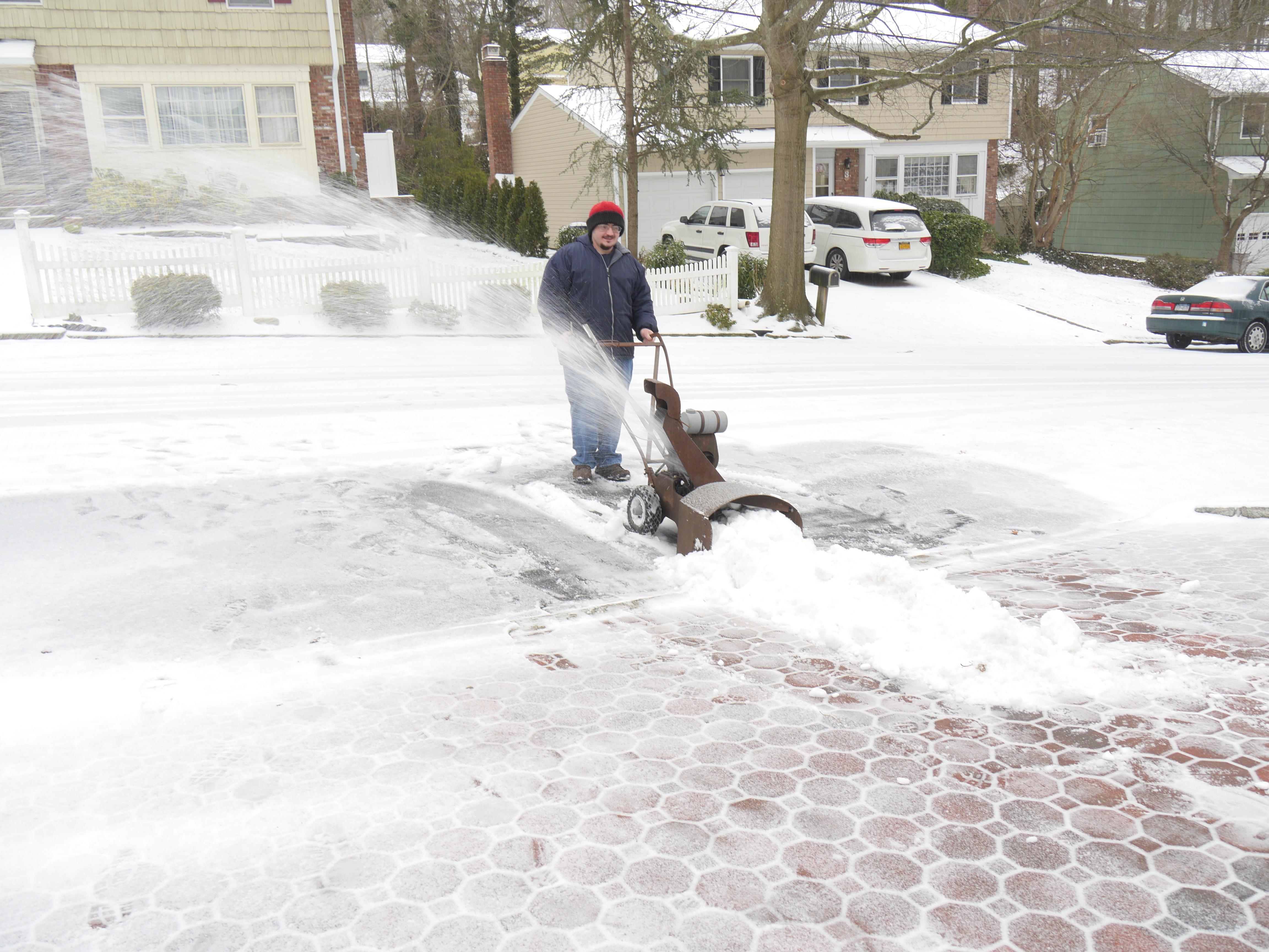
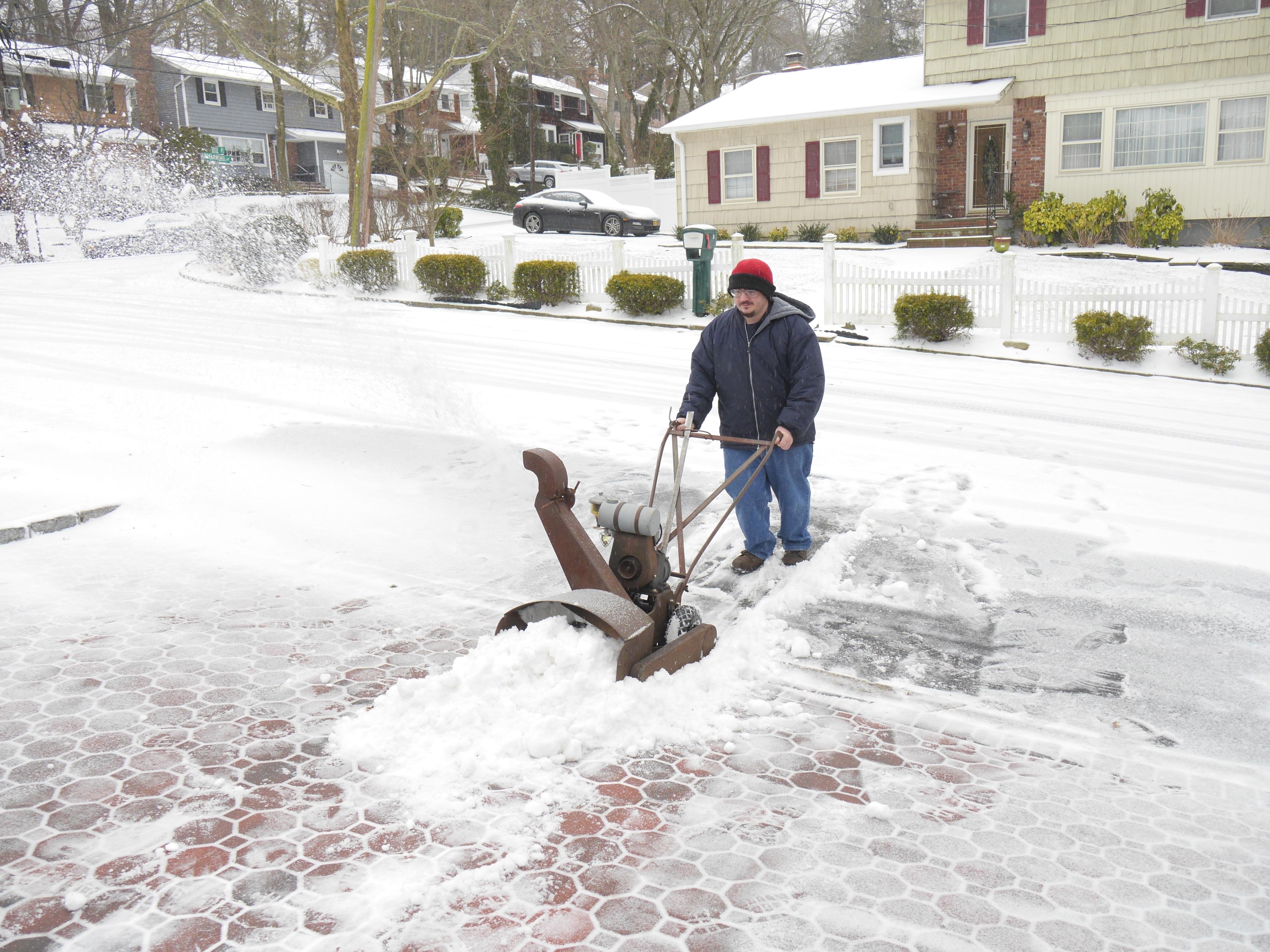
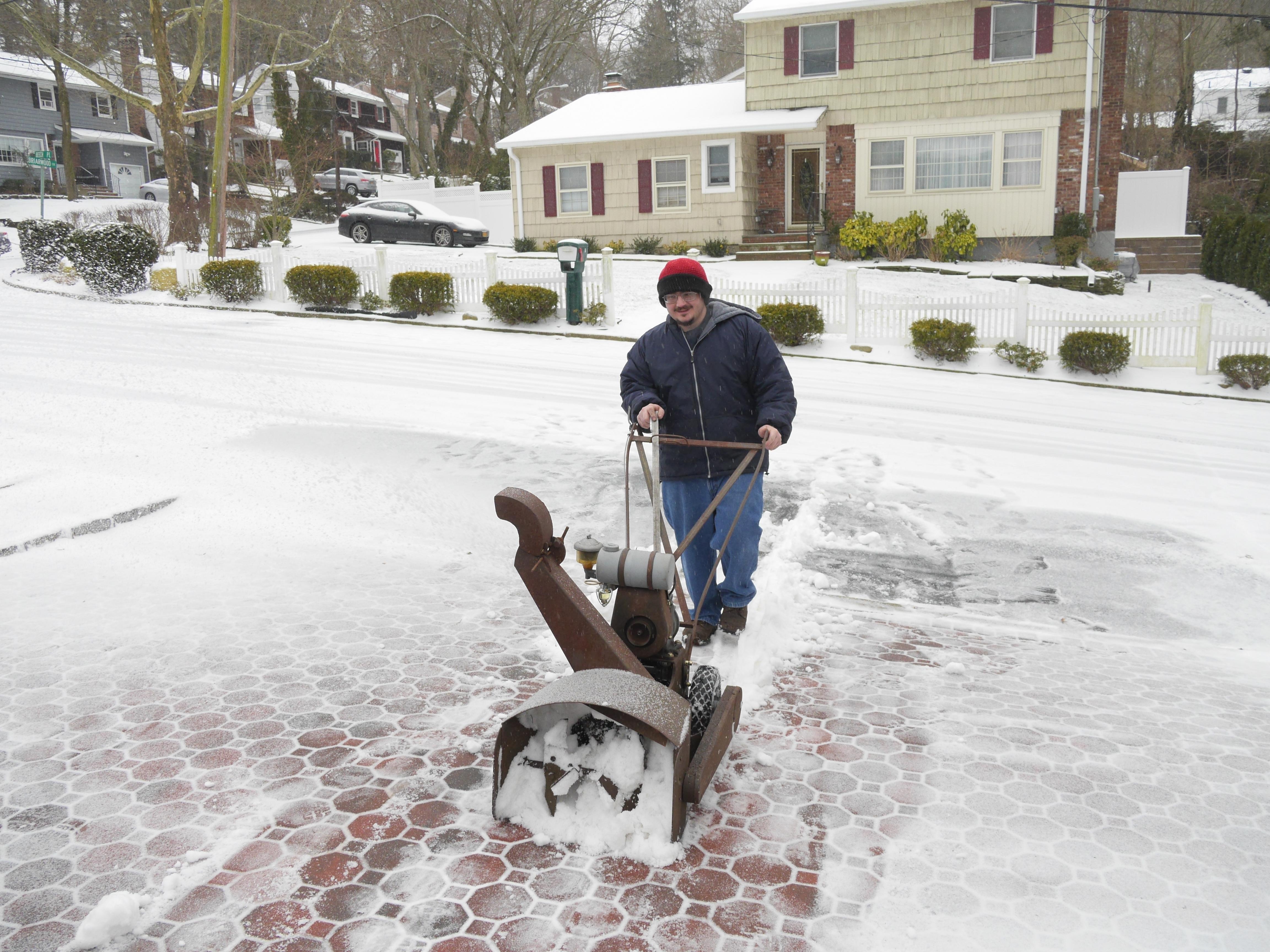
On February 12th of 2019, I had the opportunity to use my 1949 Maxim 2-19 snow thrower for the first time. There was not much of a snowstorm, but I was able to scrape together enough snow for a video of my latest project in action. For being as small as this unit is, I was quite impressed with how it handled. In this short video you will see how this machine works when trying to bite off more than it can chew and when I feather the amount of snow it can take in. As long as the tires can make contact with pavement, it works great. Once I can find some period correct tire chains this little machine should be unstoppable. I was surprised to see it throw snow 20-25ft. Clinton made a tough little engine. I couldnt be happier with how this machine runs or works. I hope you have enjoyed the restoration of this one of a kind 1949 Maxim 2-19 snow thrower.
Thanks for Reading!
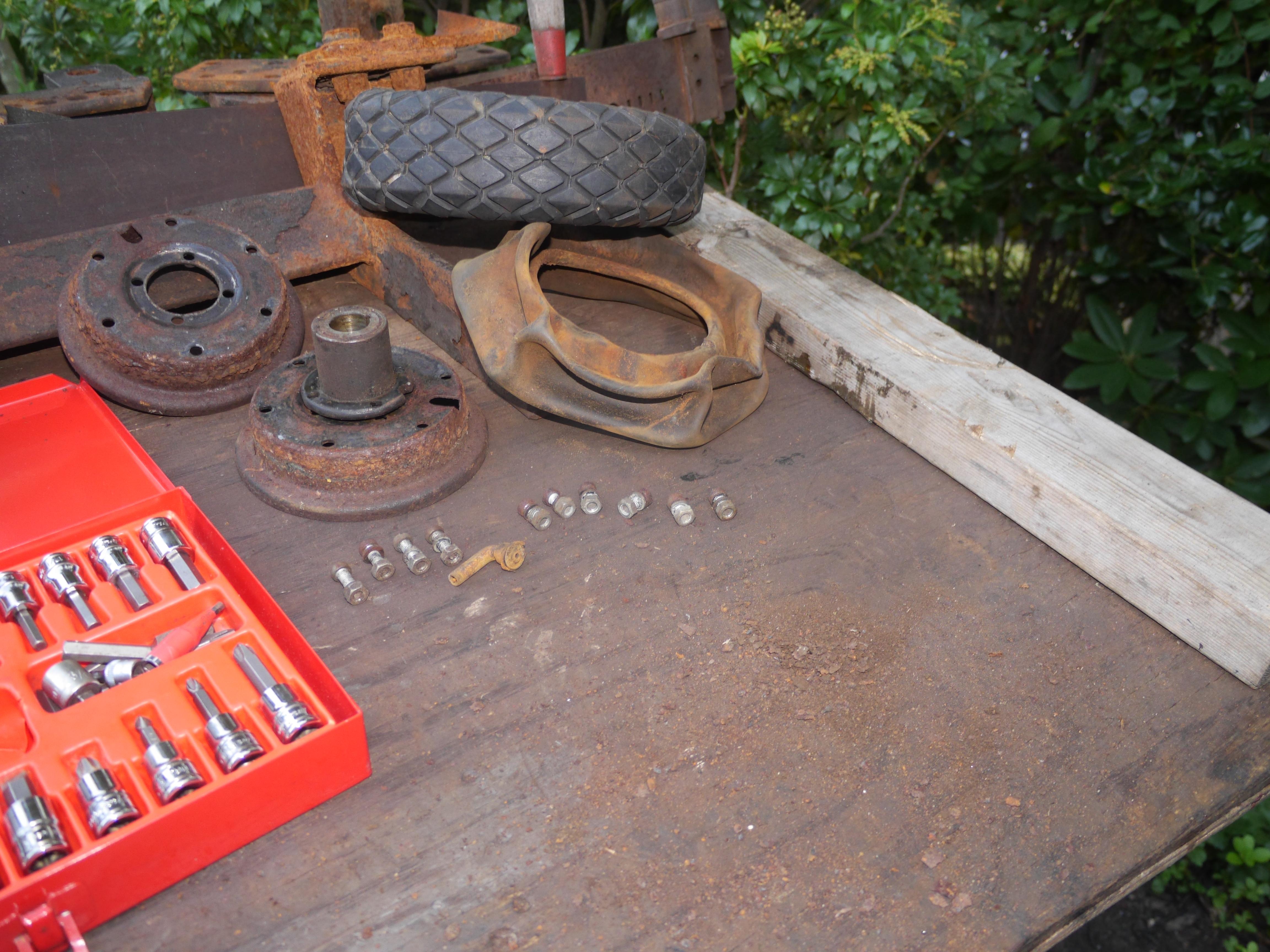
Want more? Here's a behind the scenes look at my workspace and some of the images that did not make the cut to be included in the write-up: