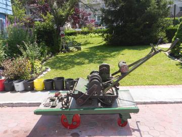
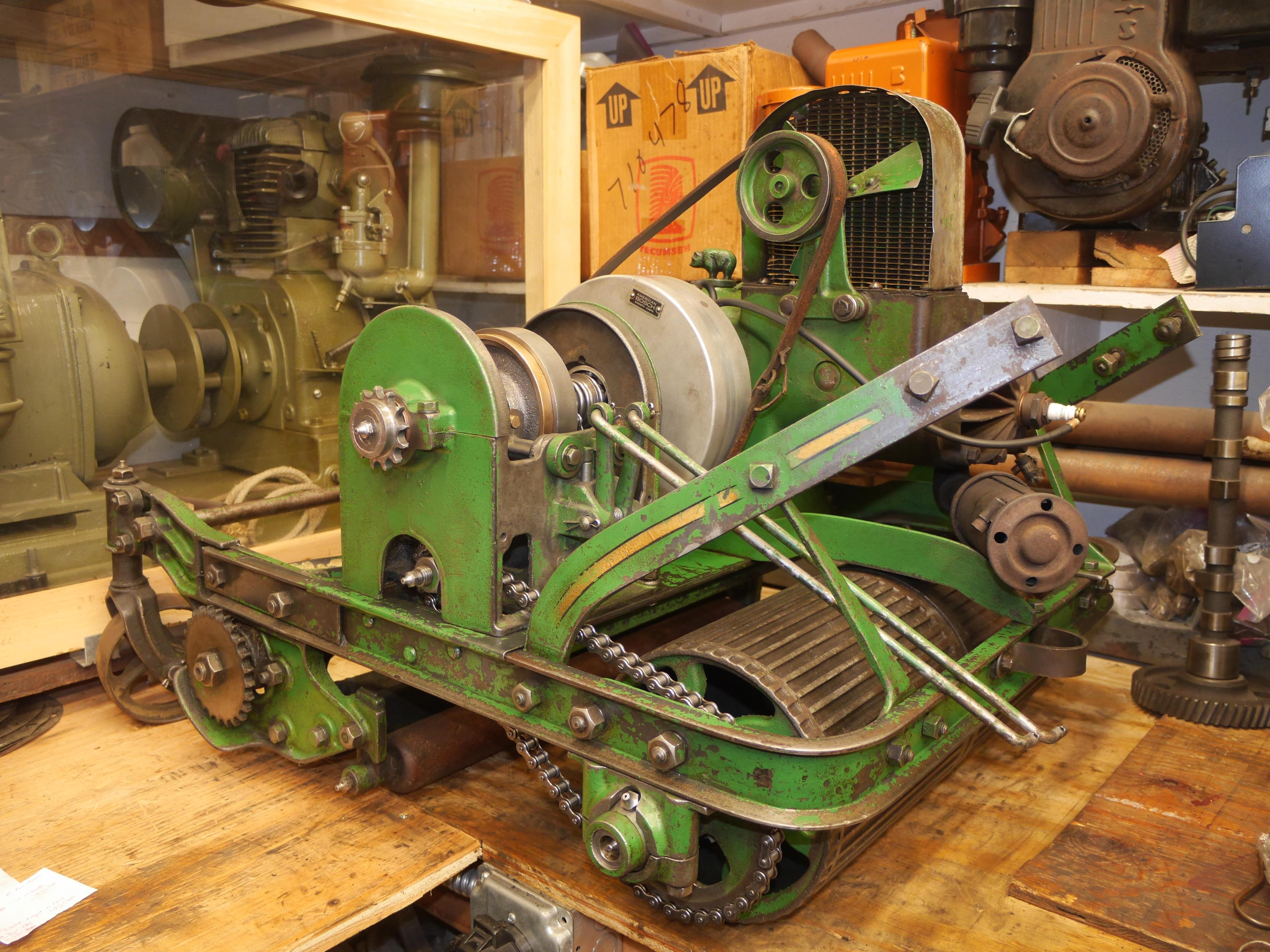
1931 Coldwell Power Lawn Mower

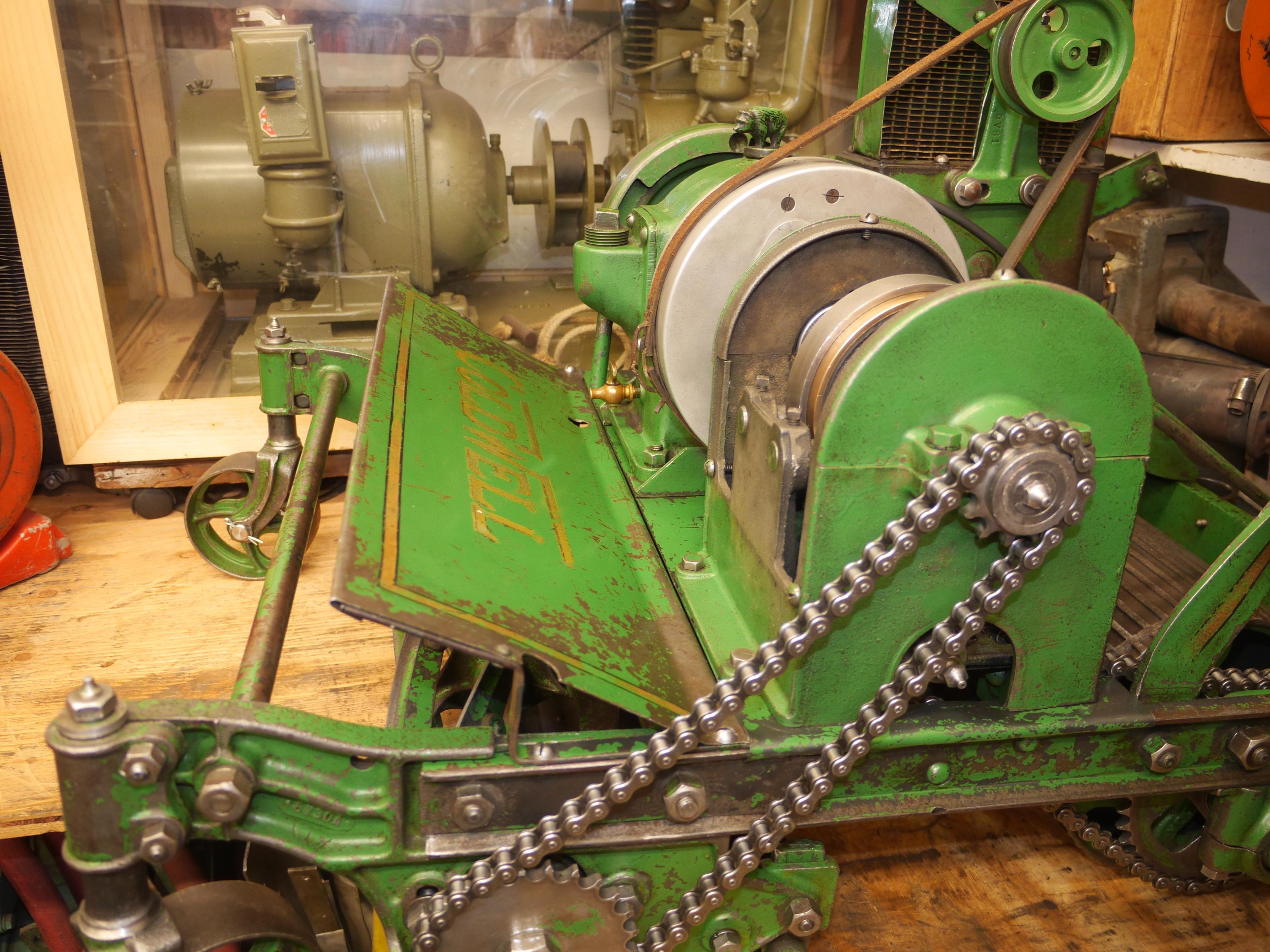
In May of 2019, a good friend of mine, Jim Tomasetti, stumbled across this 1931 Coldwell Cub lawn mower for sale at the Bernardston engine show. Jim contacted me, and we made arrangements to collect the mower. I took delivery of this mower in July of 2019. For several months this mower sat on my workbench soaking in penetrating oil, awaiting its turn in line for mechanical restoration. The entire month of April, 2020, I spent carefully disassembling, cleaning, inspecting, machining, and repairing this mower back to its glory. Coldwell was the leading manufacturer of power lawn mowers, and at the time was the only mower manufacturer endorsed by the United States Government for mowing federal allotments. Sit back and relax as I take you through all of the work that I have performed to revert ninety years of use and abuse.
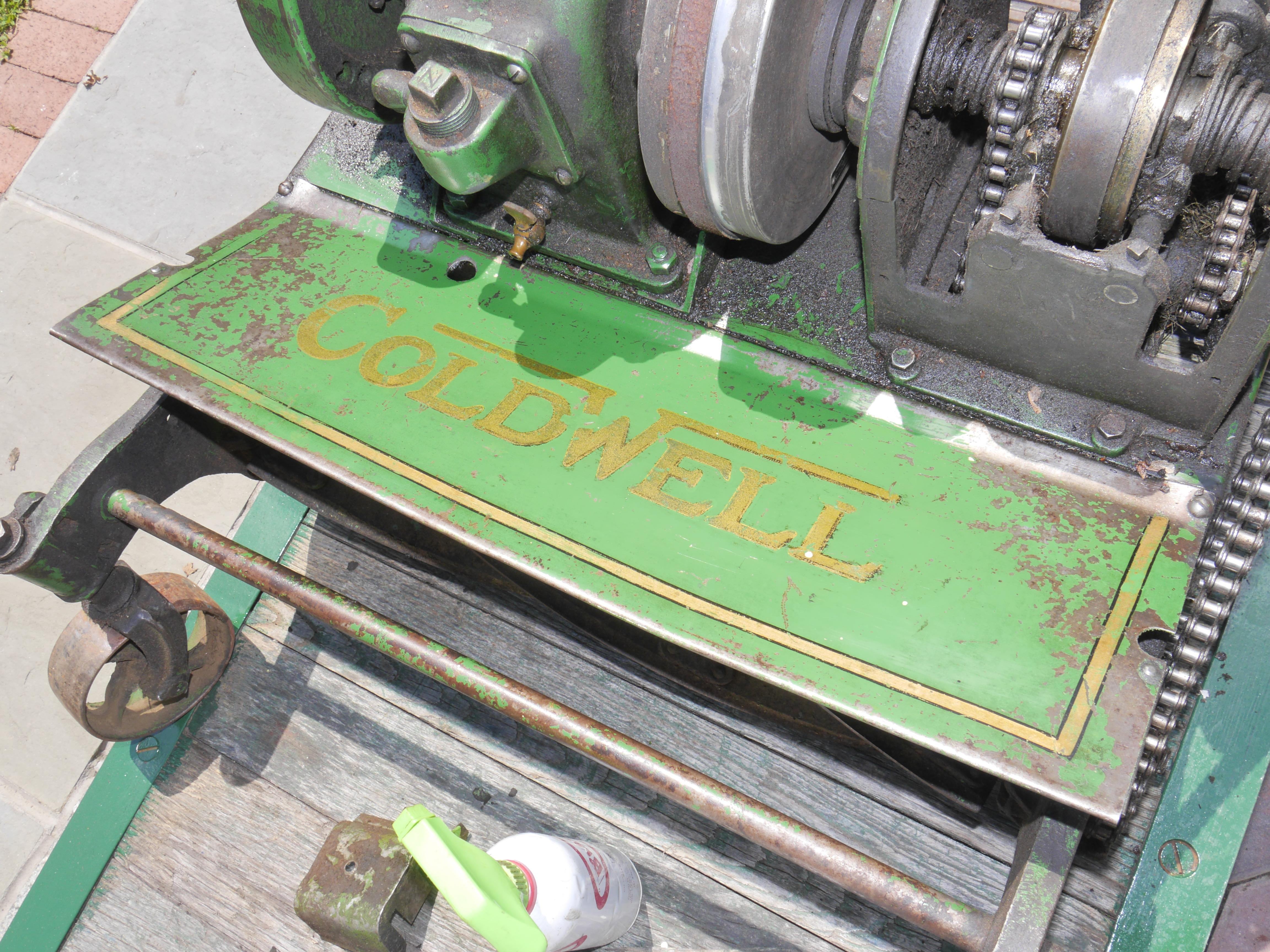
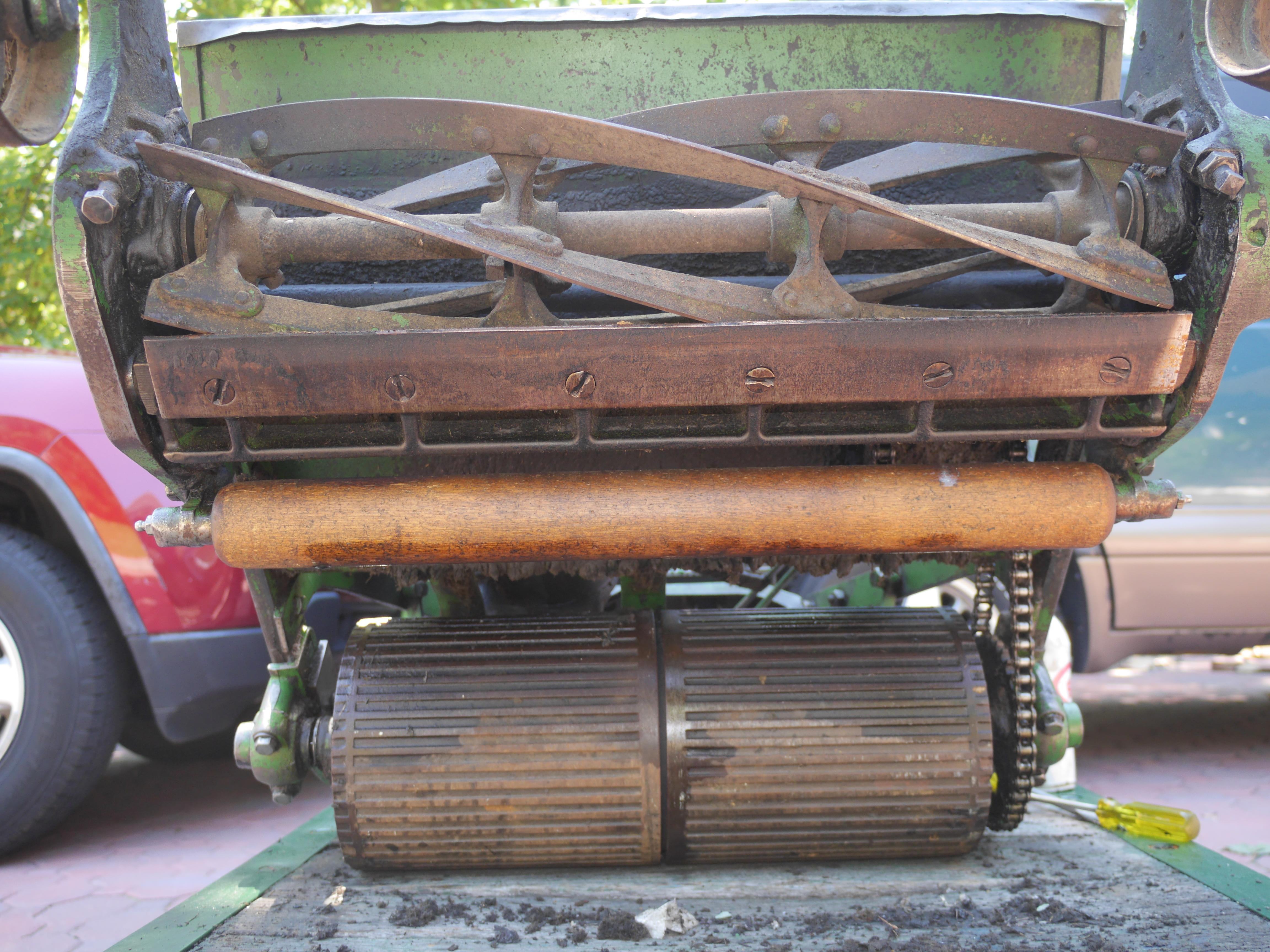
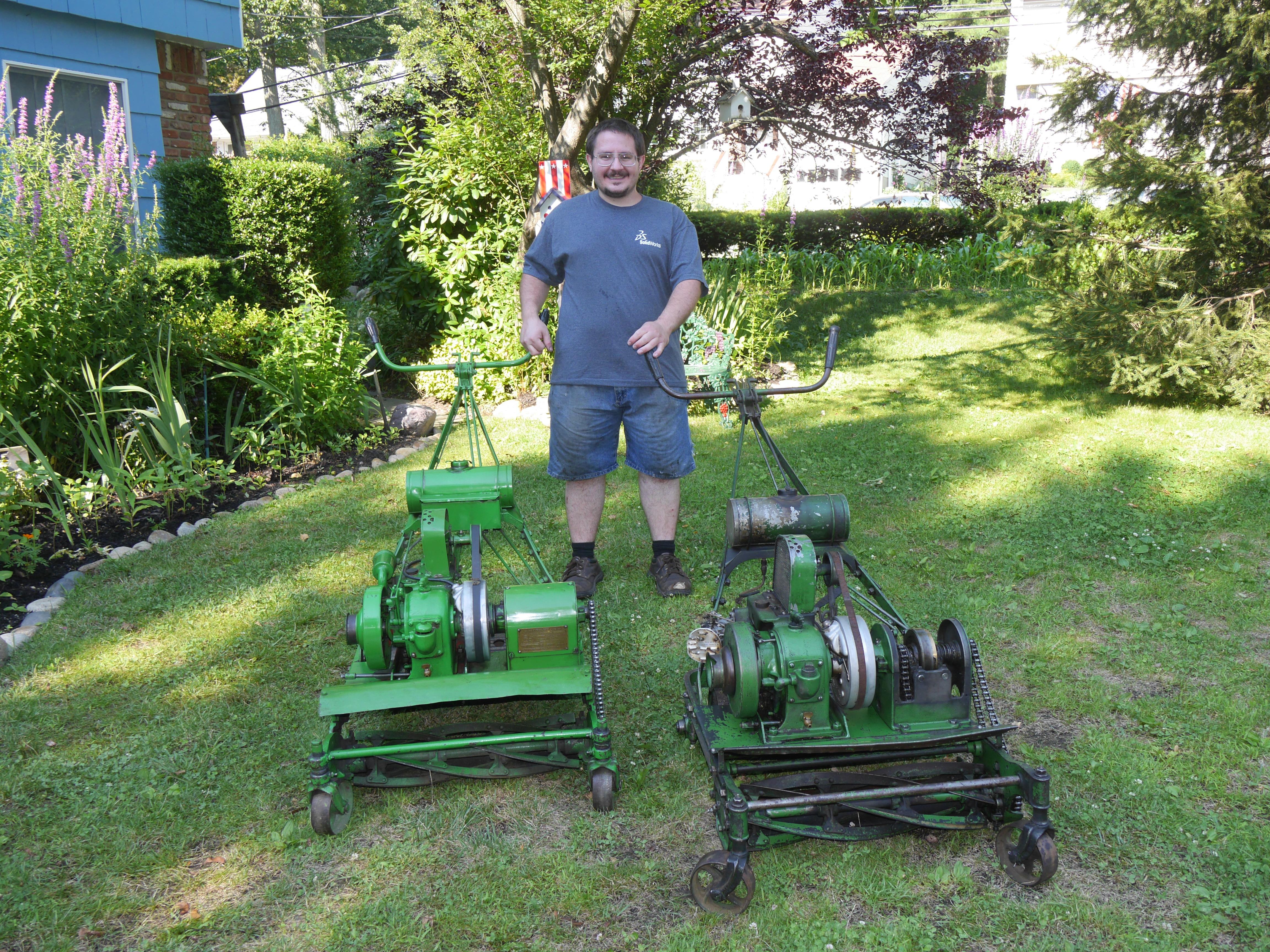
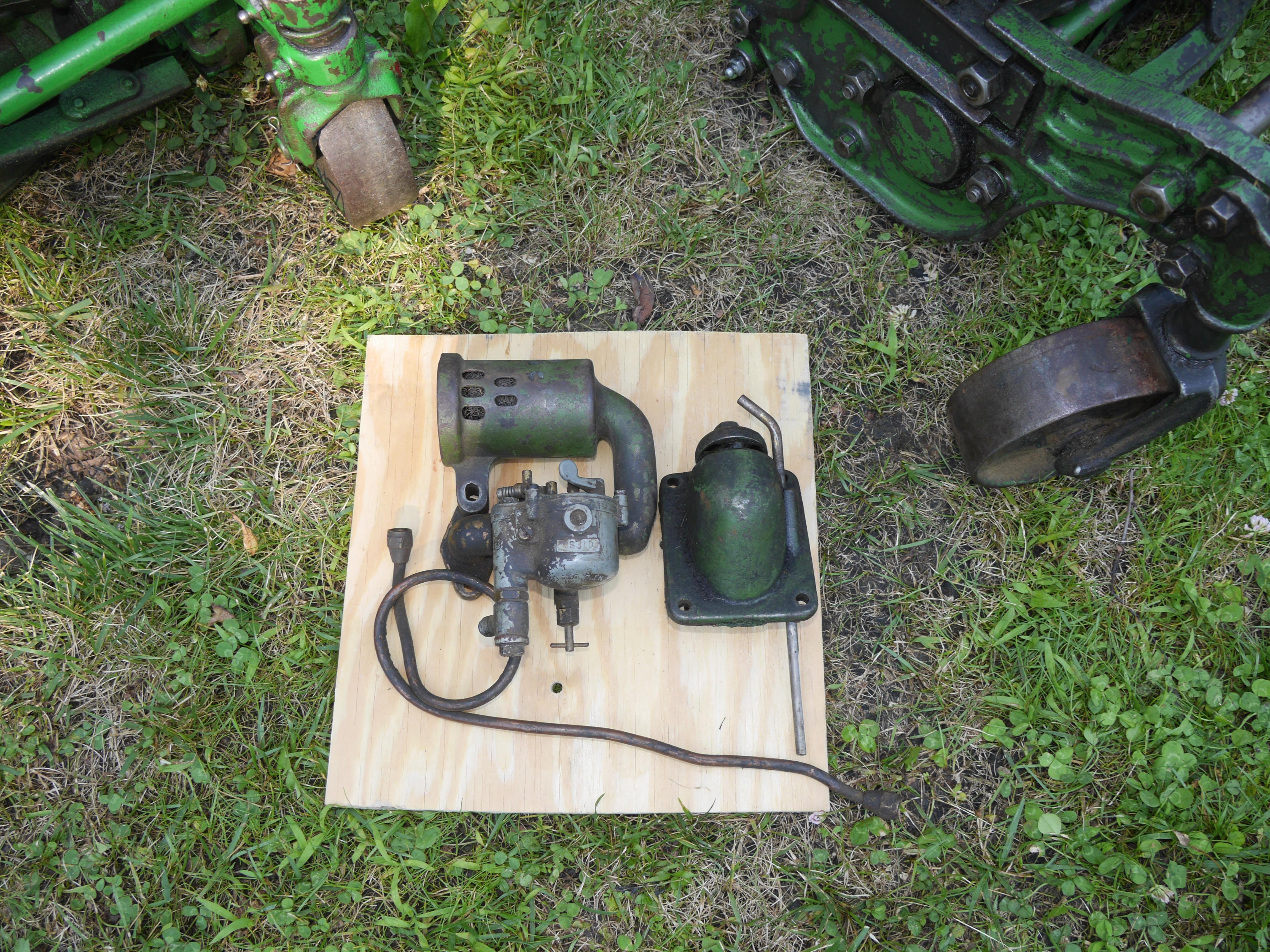
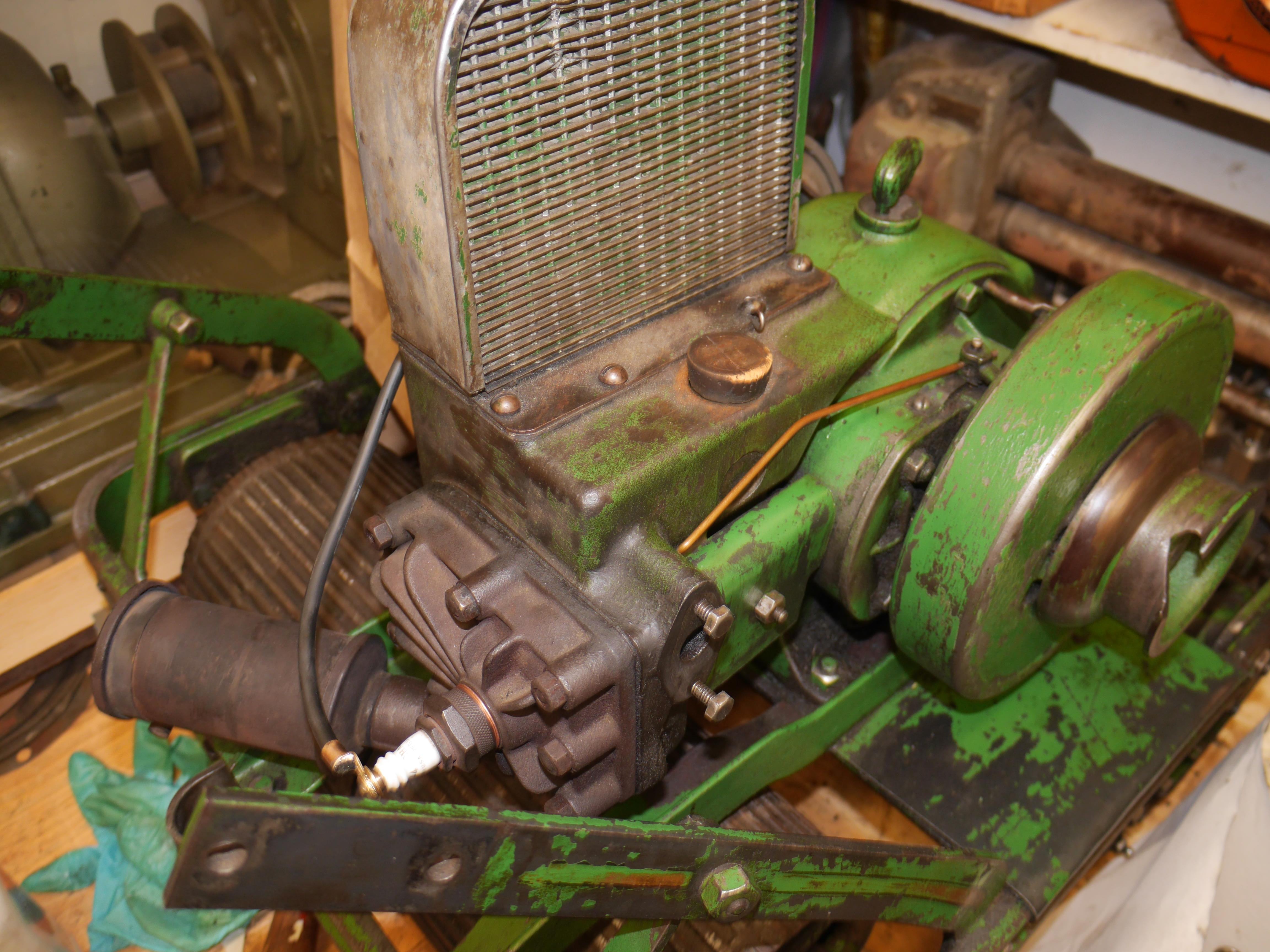
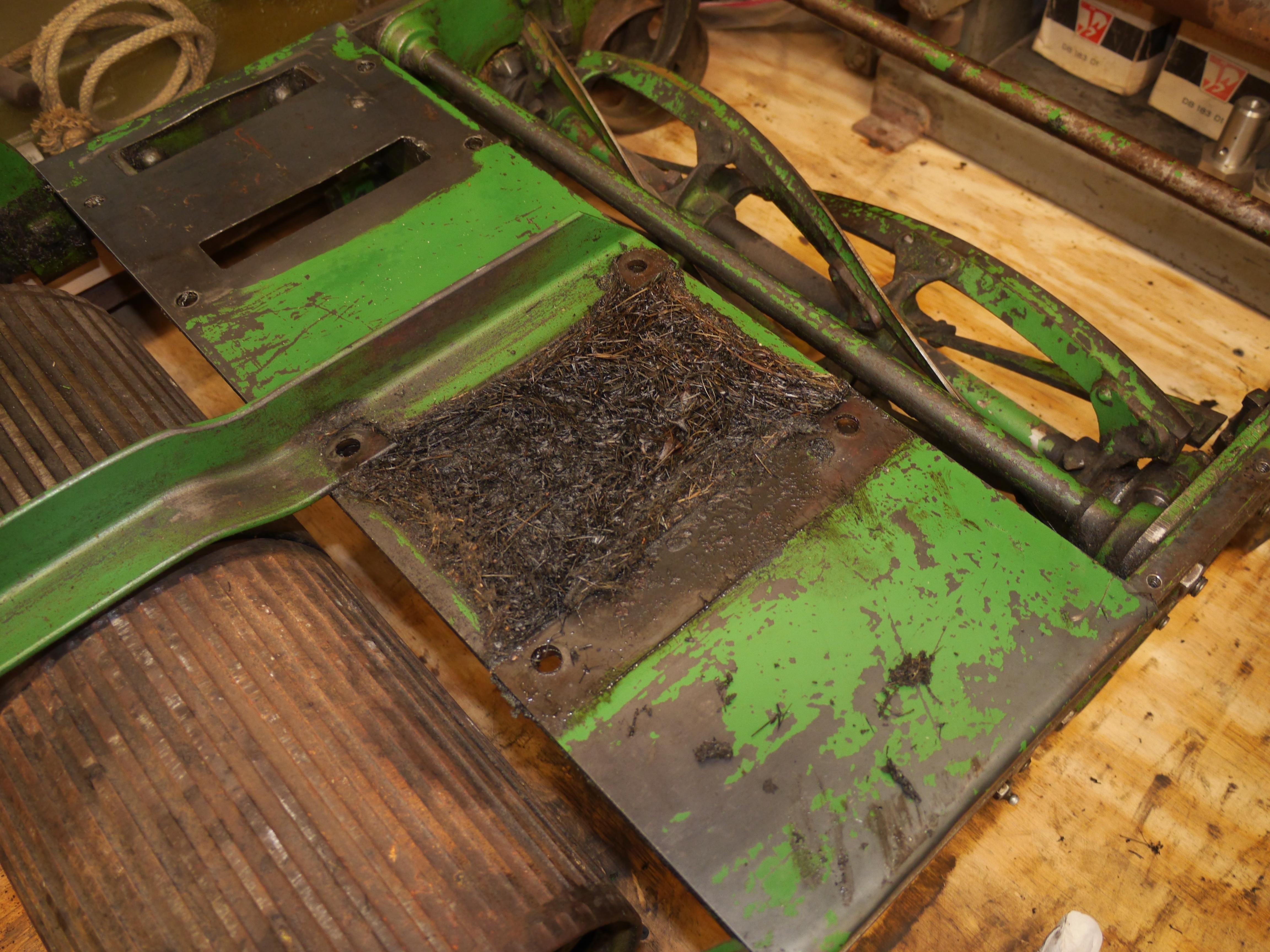
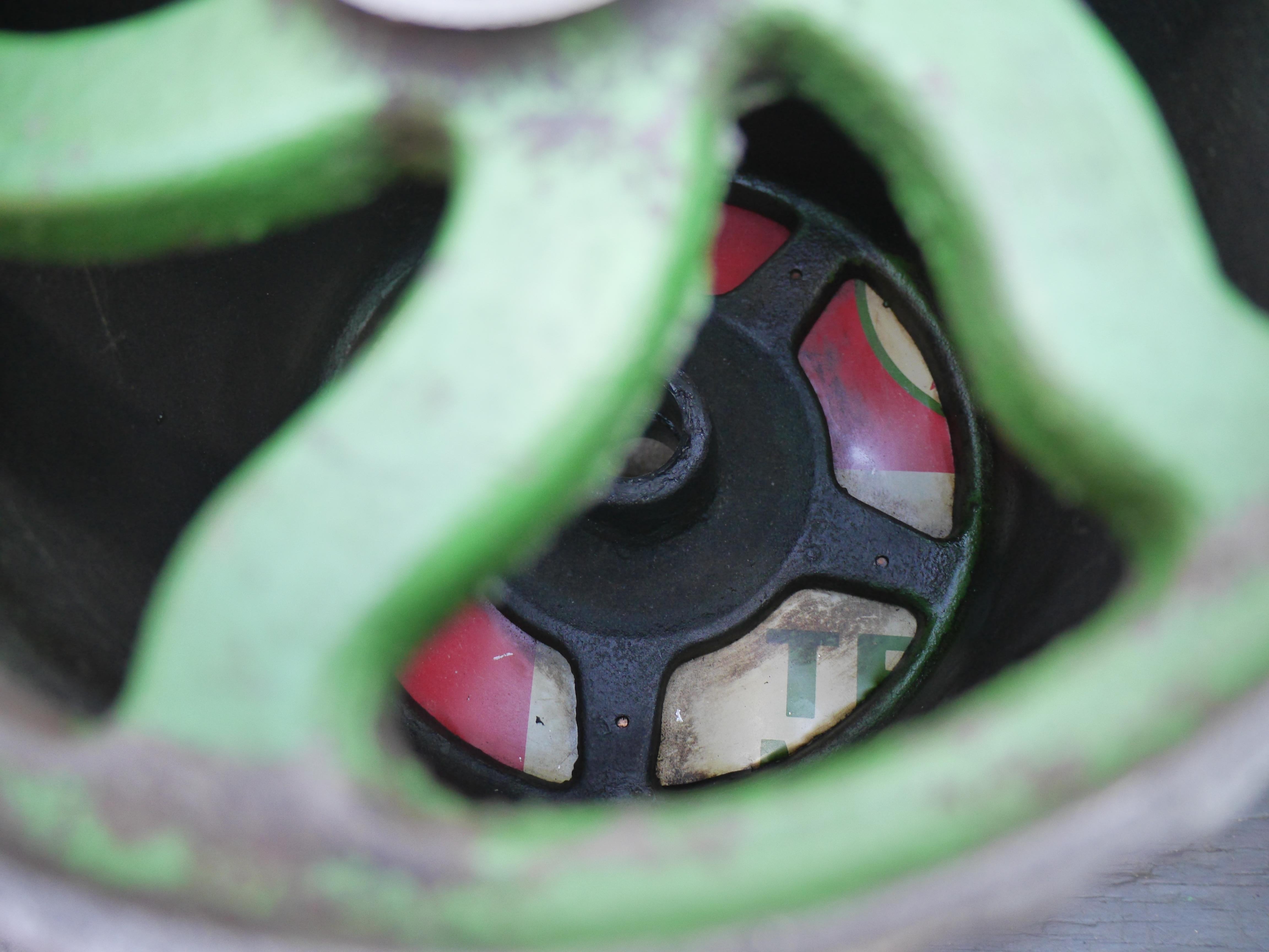
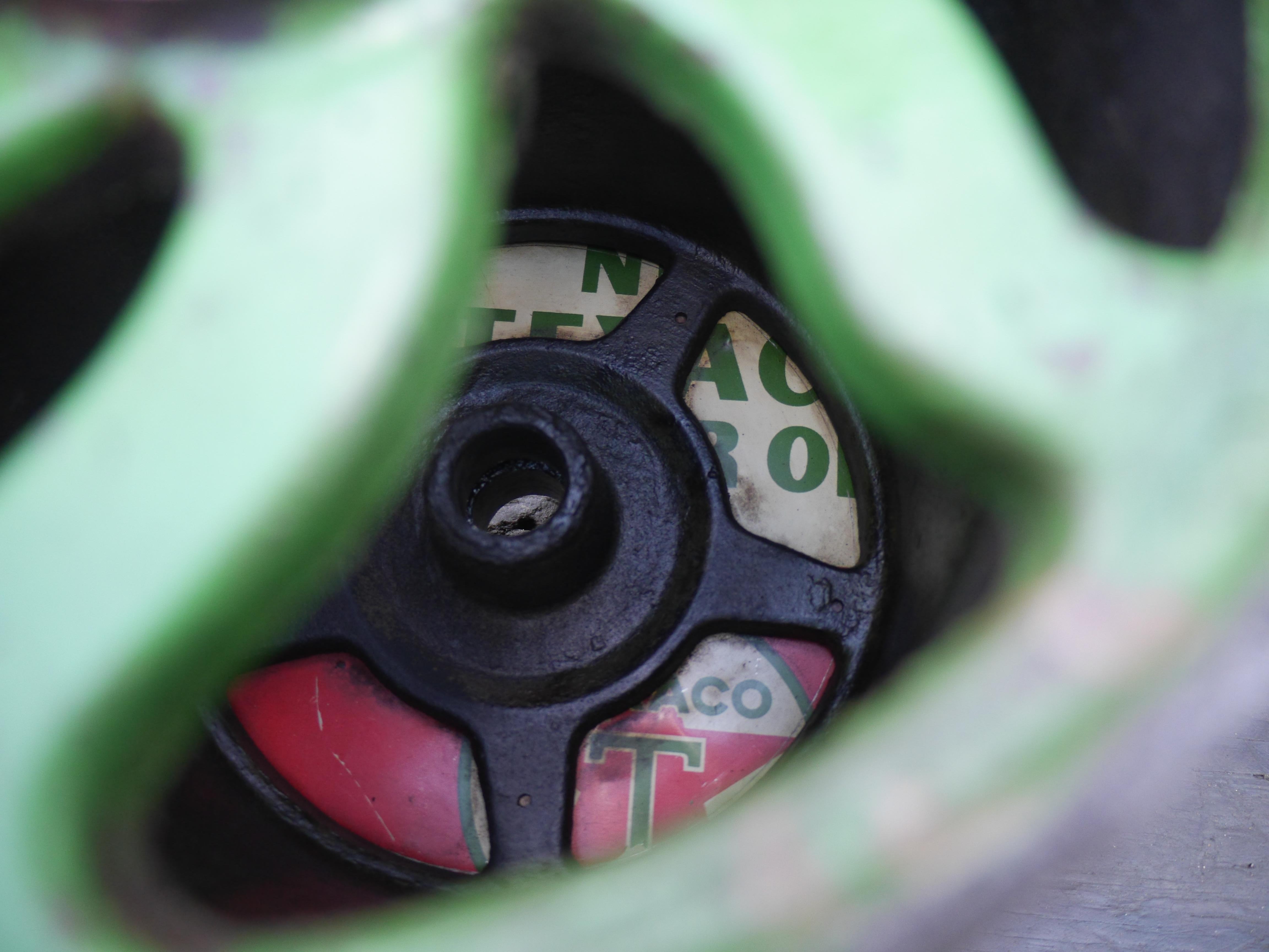
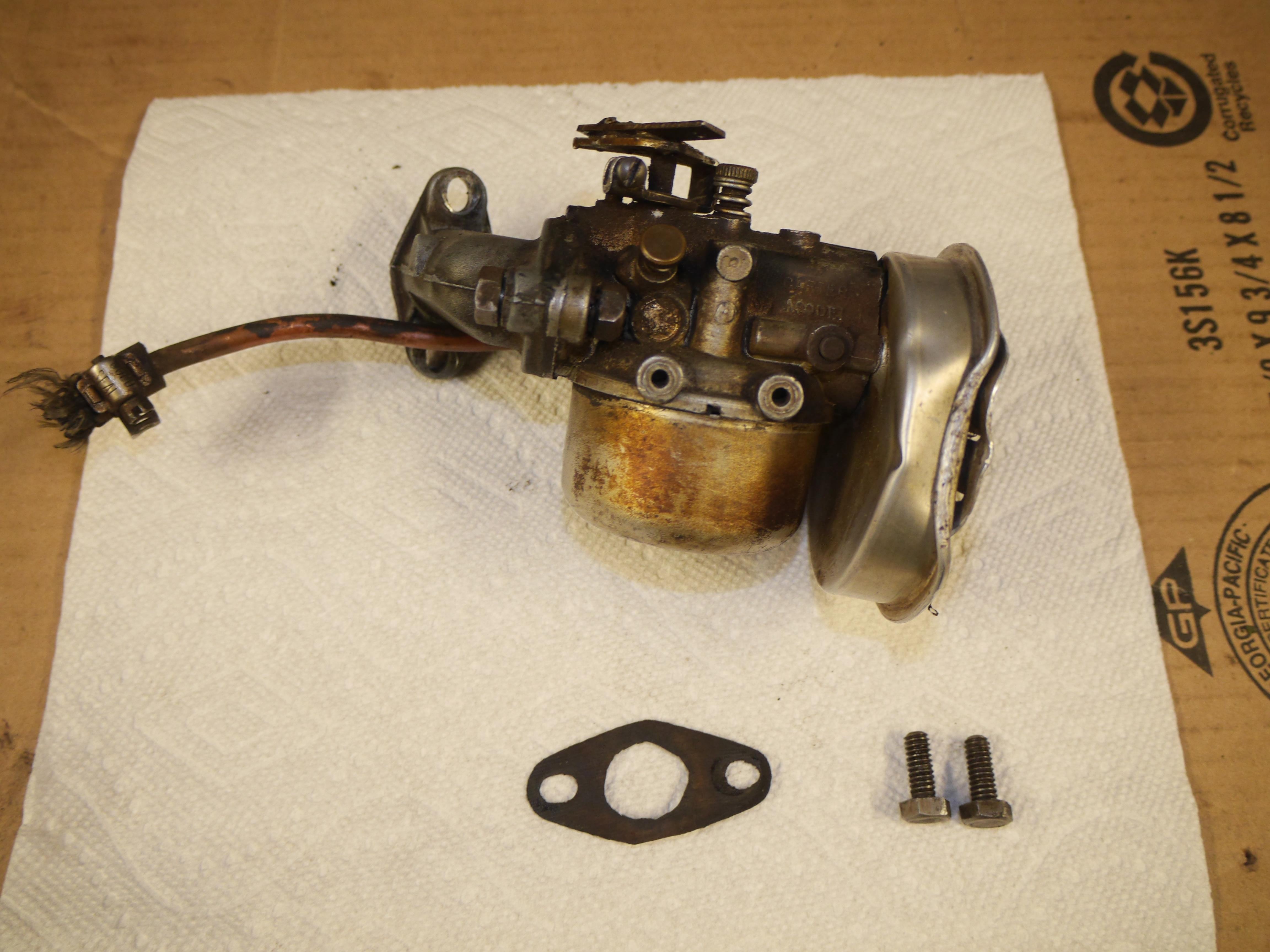
I spent most of Independence day carefully cleaning this mower. Every inch of the mower was filthy. I have never seen a reel mower greasier than this one. It is almost like whoever used it missed every grease fitting and just plastered it with grease and oil. I carefully removed approximately eight pounds of grease and dried up grass clippings that coated the underside of the machine. It is clear that the transmission/clutch cover was removed a long time ago, perhaps before the previous owner bought it, since the transmission casting was jam packed with grease-logged petrified grass. I am really excited with how nice and clean this mower is now. This mower has just wonderful original paint, pin-striping and gold leafing. I have heard about these mowers being very ornate with lots of gold leafing, but I have not see one in person with any remnant of the original leafing. This mower actually still retains a lot of the gold leafing on the individual reel knives. I just cannot believe that Coldwell leafed the reel. That is so amazing. Cleaning the mower revealed an old repair that I had not seen. The right rear drum mount has been fractured. This mower had to have been dropped at one point for that to happen. Whoever owned it simply fish-plated it back together and ran it. I am actually glad that the repair is obvious, so that I can properly fix it before I put this mower to work. It looks like the castings on both sides of the drum are identical, so it would be easy to make a mold to have a new casting made. Everything that I can see says that this mower has a lot of run time on it, but some parts show virtually no wear. For whatever reason all three of the roller chains have been replaced, the front spindle mounts are worn oval shaped, and the drum has been off before. I went to clean the differential drum drive since it is exposed, but I could not access it. Someone cut an old Texaco oil sign to fit inside of both drums to protect the differential. Perhaps the rear differential failed and a new drum was fit, because there is just no wear on the drum at all. It is over 1/4" taller than the drum on my mower which is visually worn. The front reel looks brand new, it has not been sharpened, so it may have also been replaced. The reel on my other mower has been sharpened many times since its knives are so much thinner than the ones on this mower. I discovered why the original Tillotson MS31D carburetor was removed. The lower throttle shaft bushing must have fell out and it started sucking air. It clearly wouldn't run right, so someone adapted a Carter model N carburetor. It looks like someone used a Clinton intake elbow and a Carter off a small Continental AU85 engine, since it has the same throttle shaft (under the soldered adapter) as I have seen on many Continentals. I have no idea how this engine would run with such a carburetor, but I sort of want to find out. These parts are from the 1950s, so it may have last run the 1960s. The engine sadly has absolutely no compression, so either the rings are stuck or both of the valves are not sealing. With the mower suspended, the engine will free wheel for some time when the flywheel is turned. I made some more discoveries about the engine and mower. The breather, or lack thereof is actually factory. The street elbow and pipe nipple is actually rotated too far towards the engine. It is supposed to run vertically down under the reel cover. Someone actually cut the end off, as it is supposed to go through the cover. I finally know what that hole in the reel guard is for! With my other cub sitting next to this one, I discovered that this engine never had any provision for a three speed governor. It must have only been a single speed mower. I also discovered that this mower did not have a toolbox either, there simply is no mounting for one. So in reality this mower is only missing the transmission cover and brass identification tag. That is good news! The bad news is that the transmission is locked up and needs to come completely apart to be repaired. Both the power drive and reel clutch levers and linkages move, but they are stuck to the central clutch material. It is going to be a challenge cleaning everything up without damaging any of the original paint. There are quite a few parts that need to come apart to thoroughly clean everything. Luckily the transmission on my other cub is almost identical, so I should be able to fix it without too much trouble. I wish I knew where the serial number was stamped into these machines if anywhere. All that I uncovered was an H cast into the engine block. The serial number has to be somewhere other than on the missing brass id tag. I made a 14 minute video of my two Coldwell mowers side by side, I hope you all enjoy. I am learning more and more about these mowers, and think I need a few more of them to complete the picture! Perhaps a steam powered Coldwell! Oh how nice it is to dream! At this point I think this mower was built around 1931.


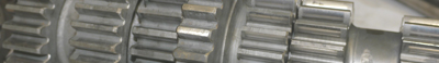
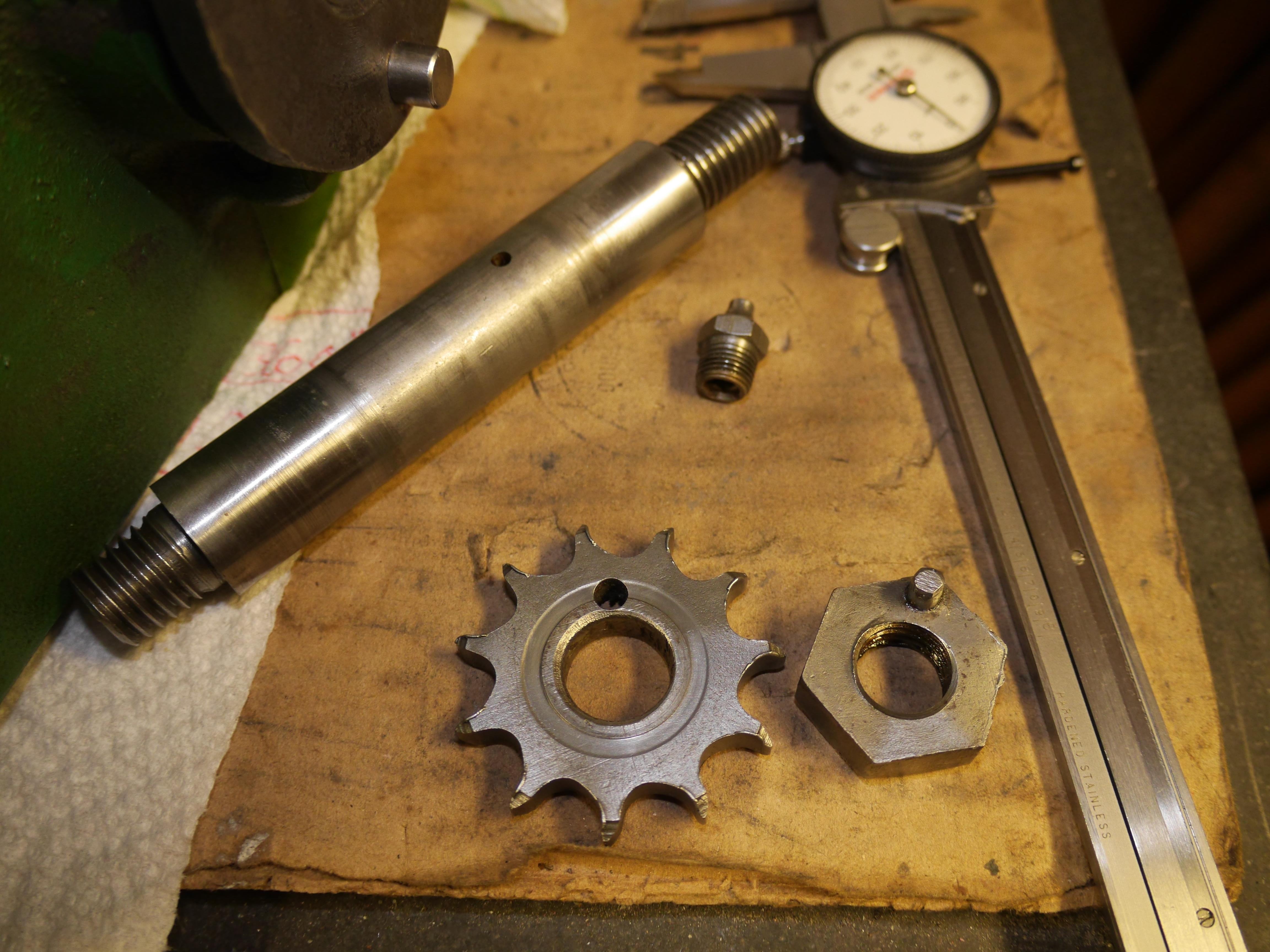
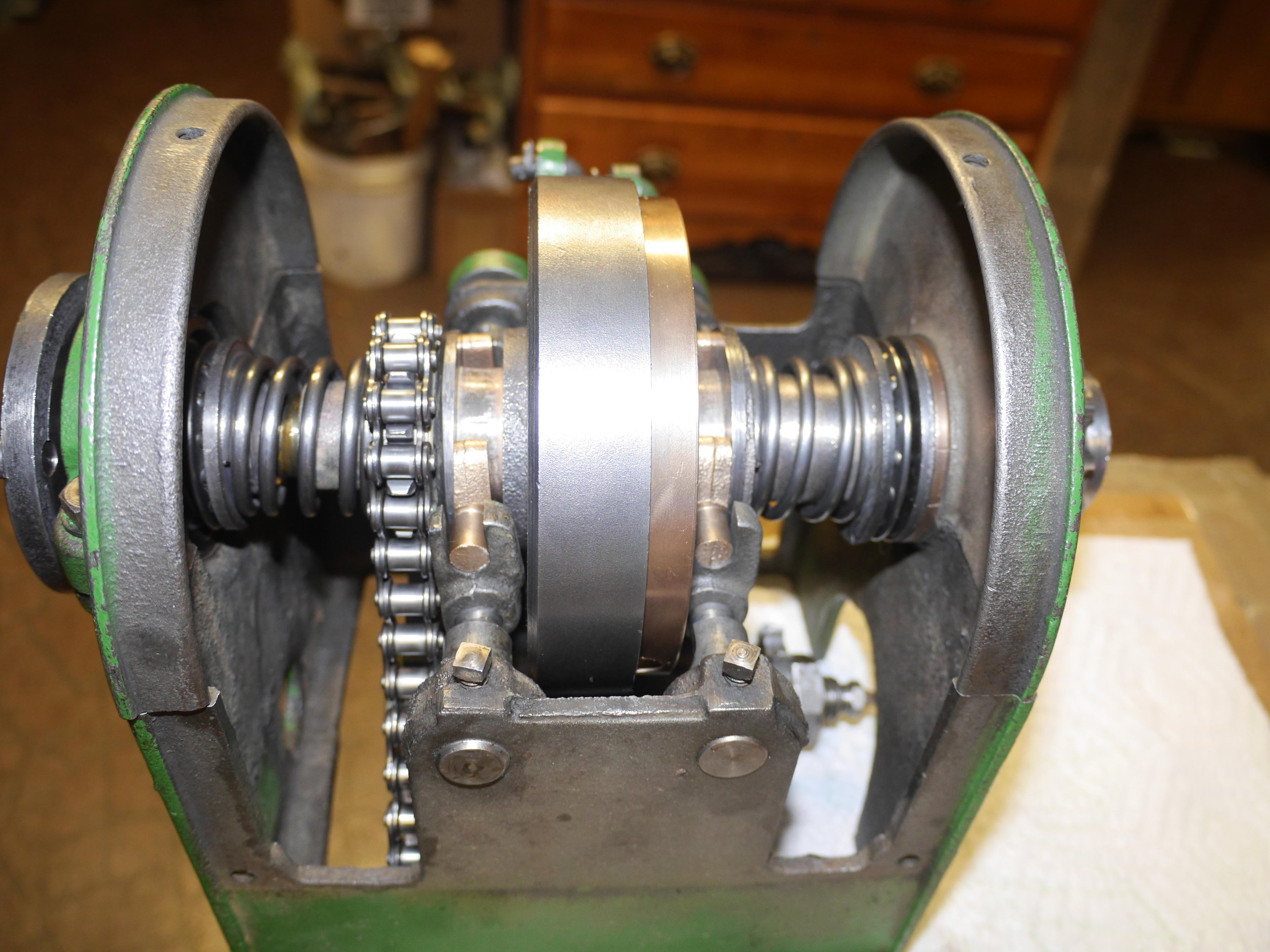
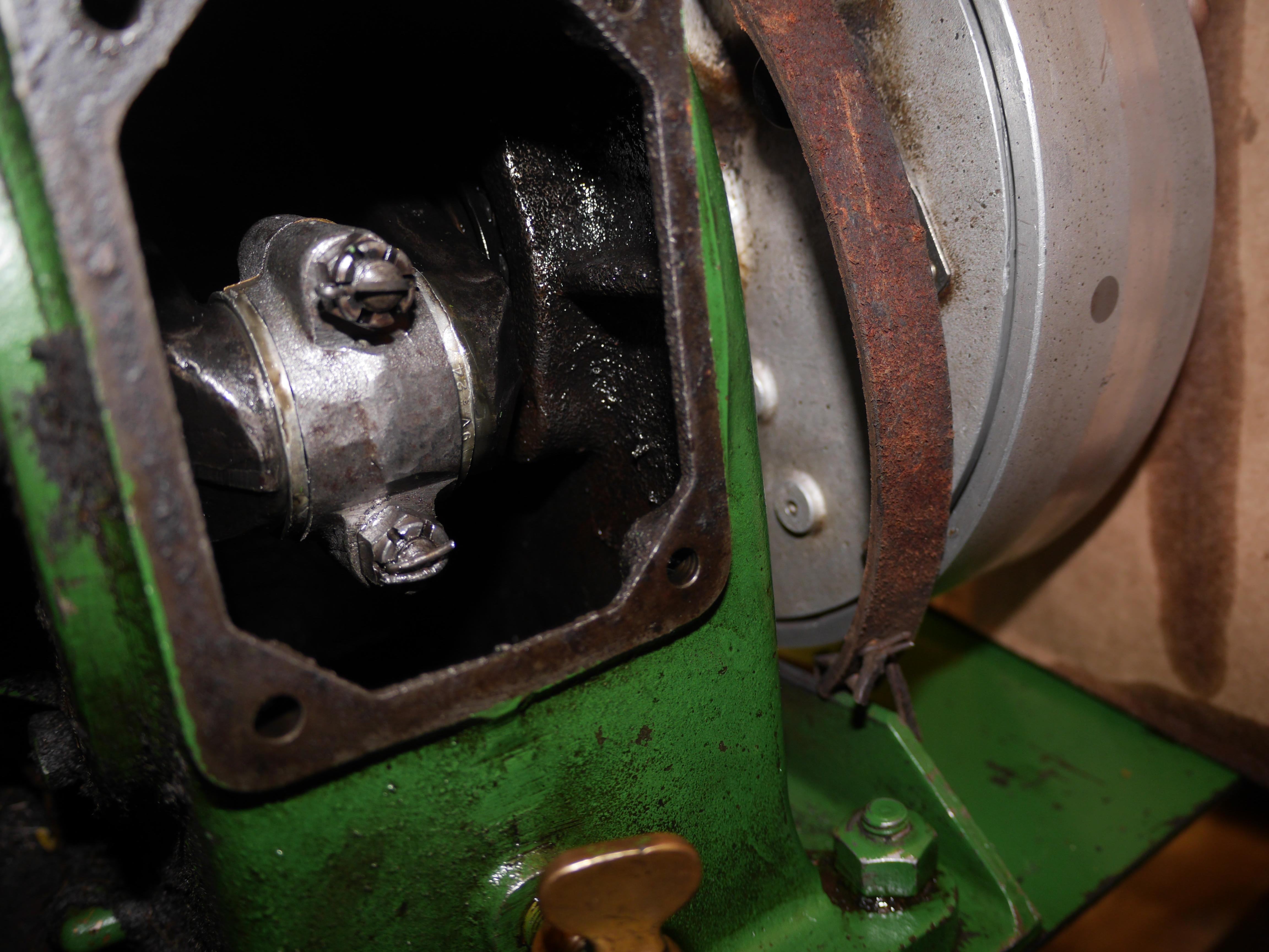
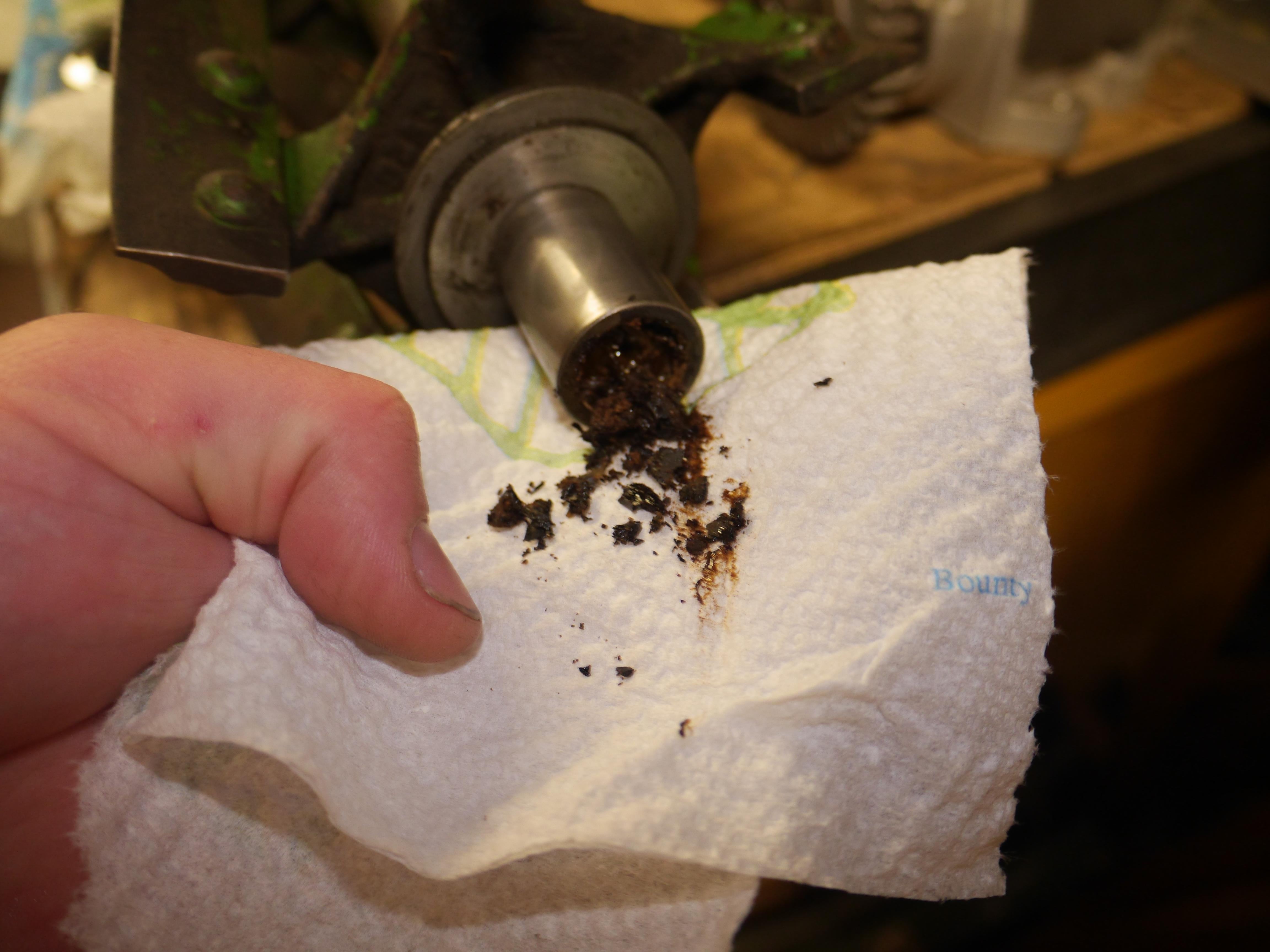
The first week in April I decided to start working on my 1931 Coldwell Cub. It has more or less consumed a good area of my workbench for the last nine months, so it is time to do something with it. Knowing that the clutches were stuck in gear, I started by removing the transmission from the mower. I carefully removed the remaining wads of petrified grease/grass, and began soaking the transmission in penetrating oil. With a brush, a few wood scrapers, and some fuel I began cleaning the transmission case until it was workable. I removed the upper bearing supports to separate the jackshaft from the transmission case. I cleaned off as much of the heavy crud that I could before submerging the jackshaft in my ultrasonic cleaner. The petrified grease did a good job sticking everything together. After three hours in the cleaner, everything came out nice and clean. The two pieces of the jackshaft separated and all of the loosened grease was removed. The reassembly of the transmission went nice and smooth. Everything went back together as it should, and low and behold the reel and drive clutch moved freely. There is a little bit of wear on the drive clutch side of the transmission. The bronze clutch fork for the power drive is worn 0.070" thinner than the fork for the reel. This has caused the cast iron yoke to contact the roller chain which runs to the output shaft of the transmission. The best repair would be to cast/machine a new clutch fork for the power drive, but for now I am going to simply machine a longer pin to take up the slop in the lever type control setup. This will allow me to put the mower in neutral, and operate the drive clutch as it should until I can make a new clutch fork for this mower. The only other piece which showed any wear was the #40 13 tooth output shaft sprocket which sees a lot of dirt picked up from the roller chain and drum drive, and of course the continual shock loading of moving the approximately four hundred pound mower. The worn sprocket is actually quite a neat piece in itself. I have never seen a thin sprocket simply held in place by a pin. It will be easy to machine a new sprocket for this in the future.
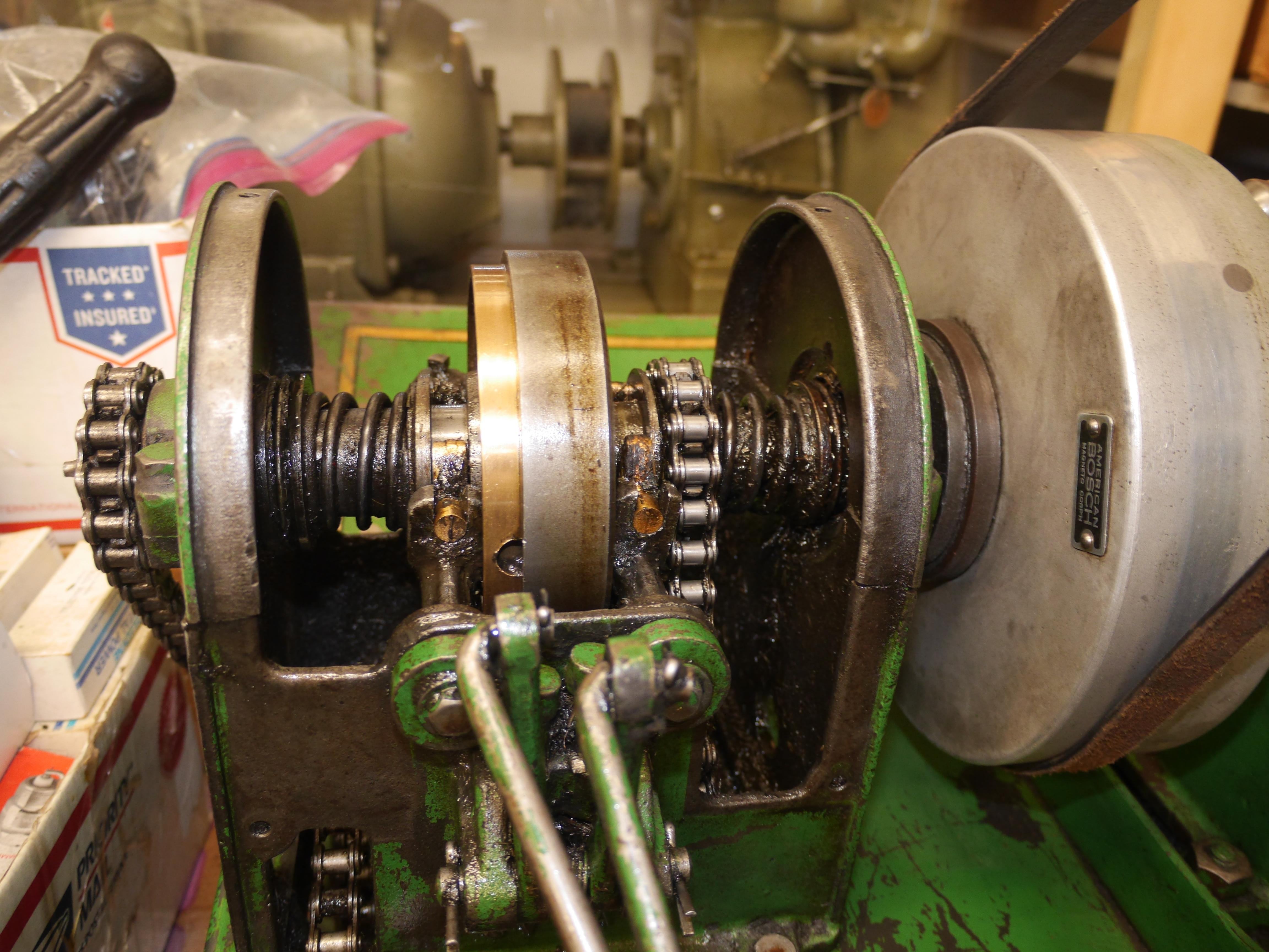

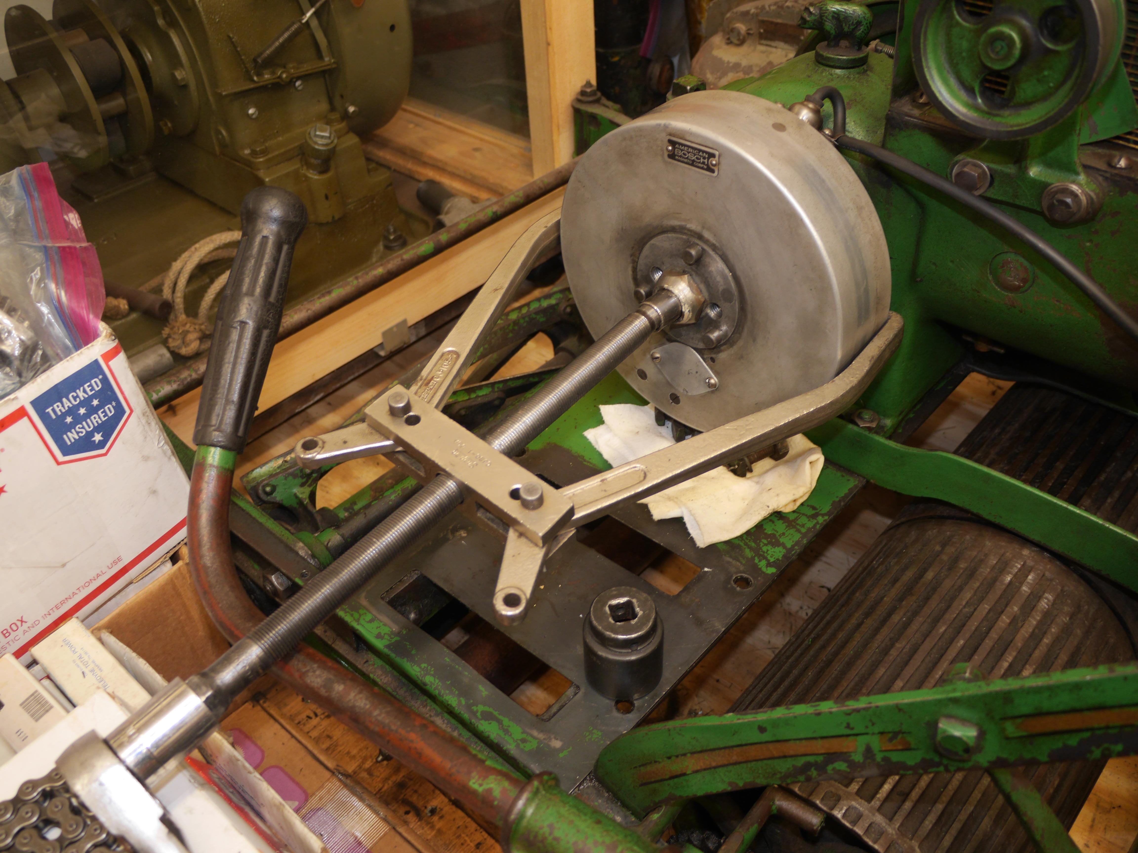
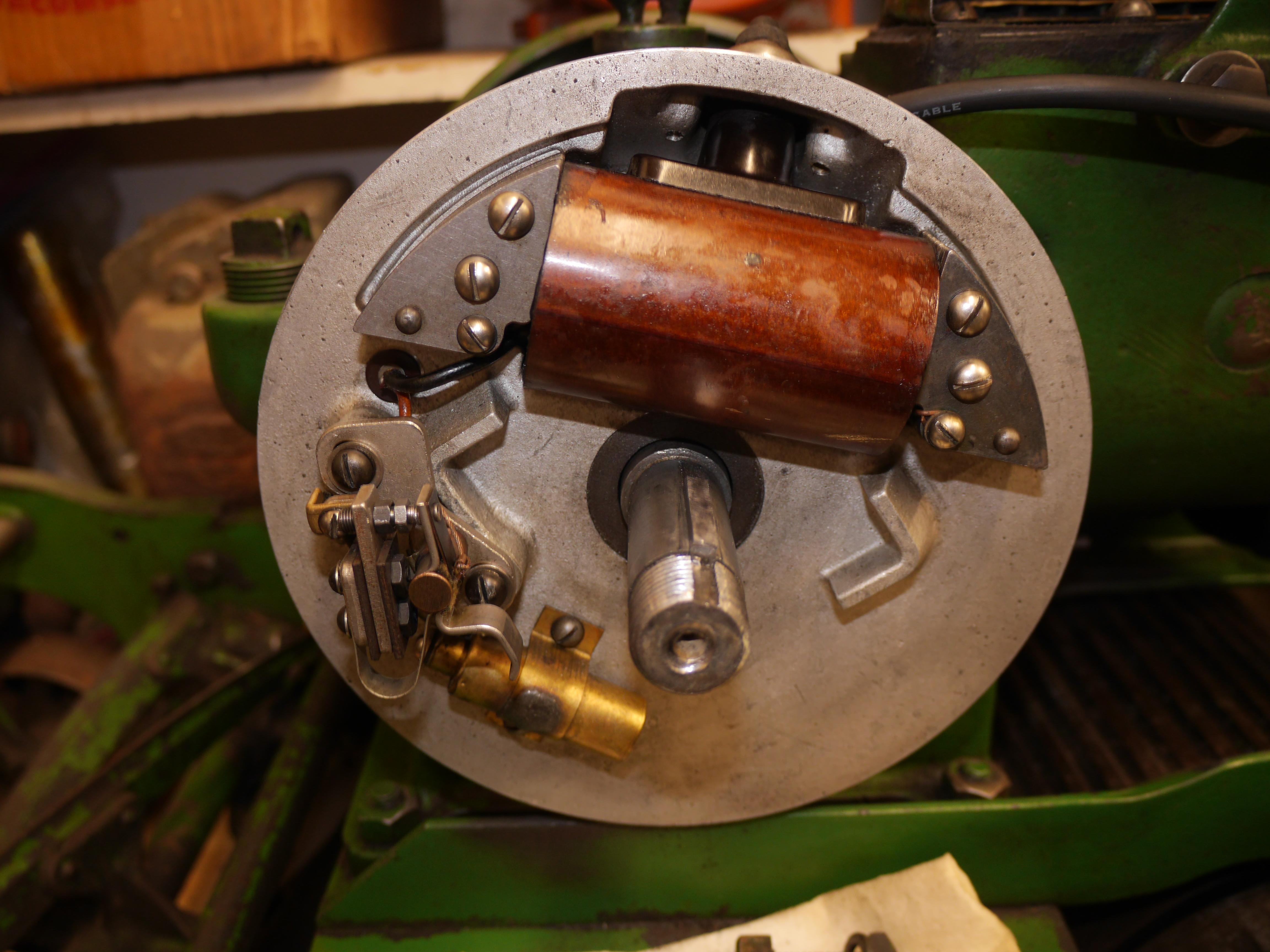
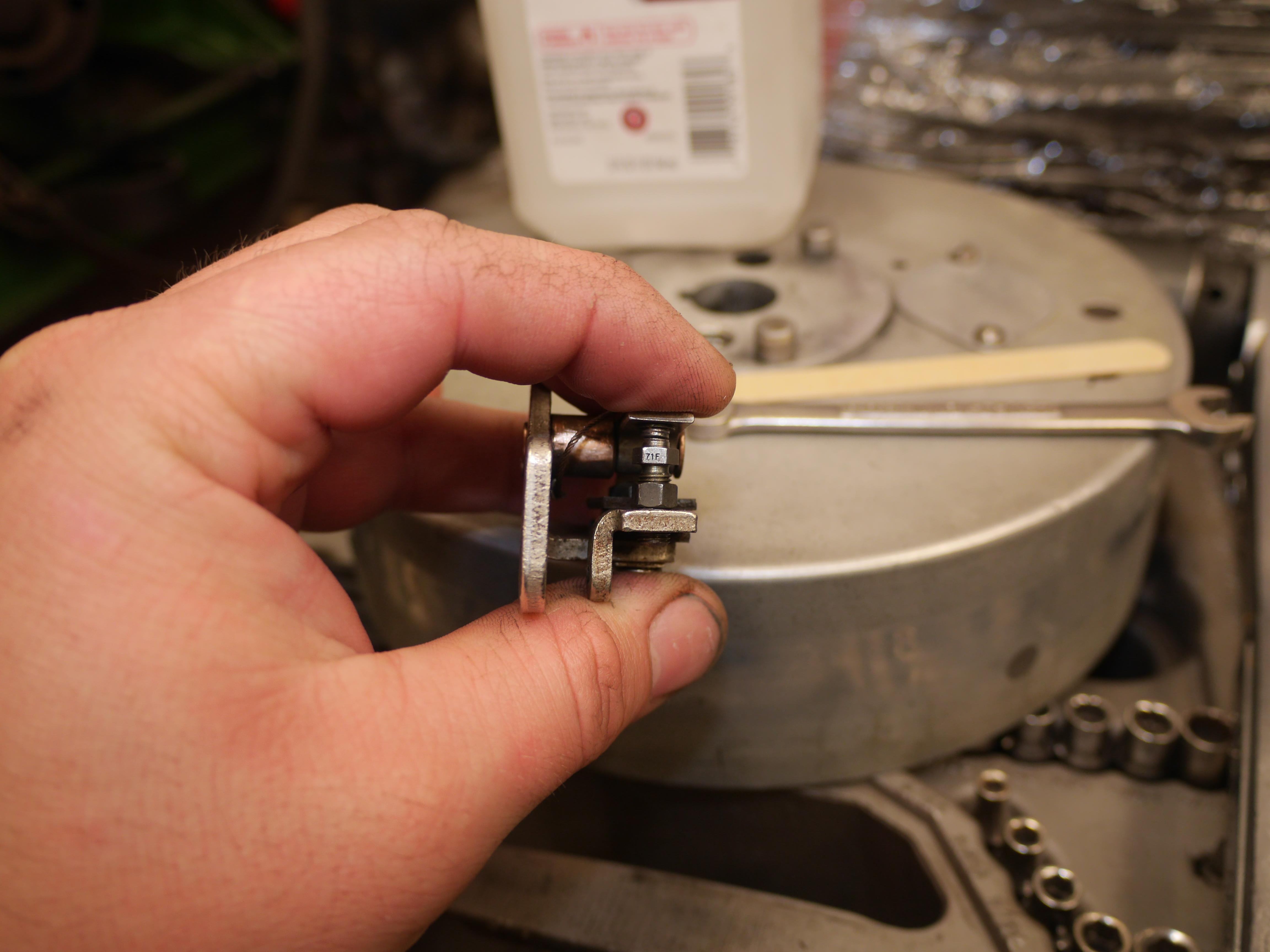
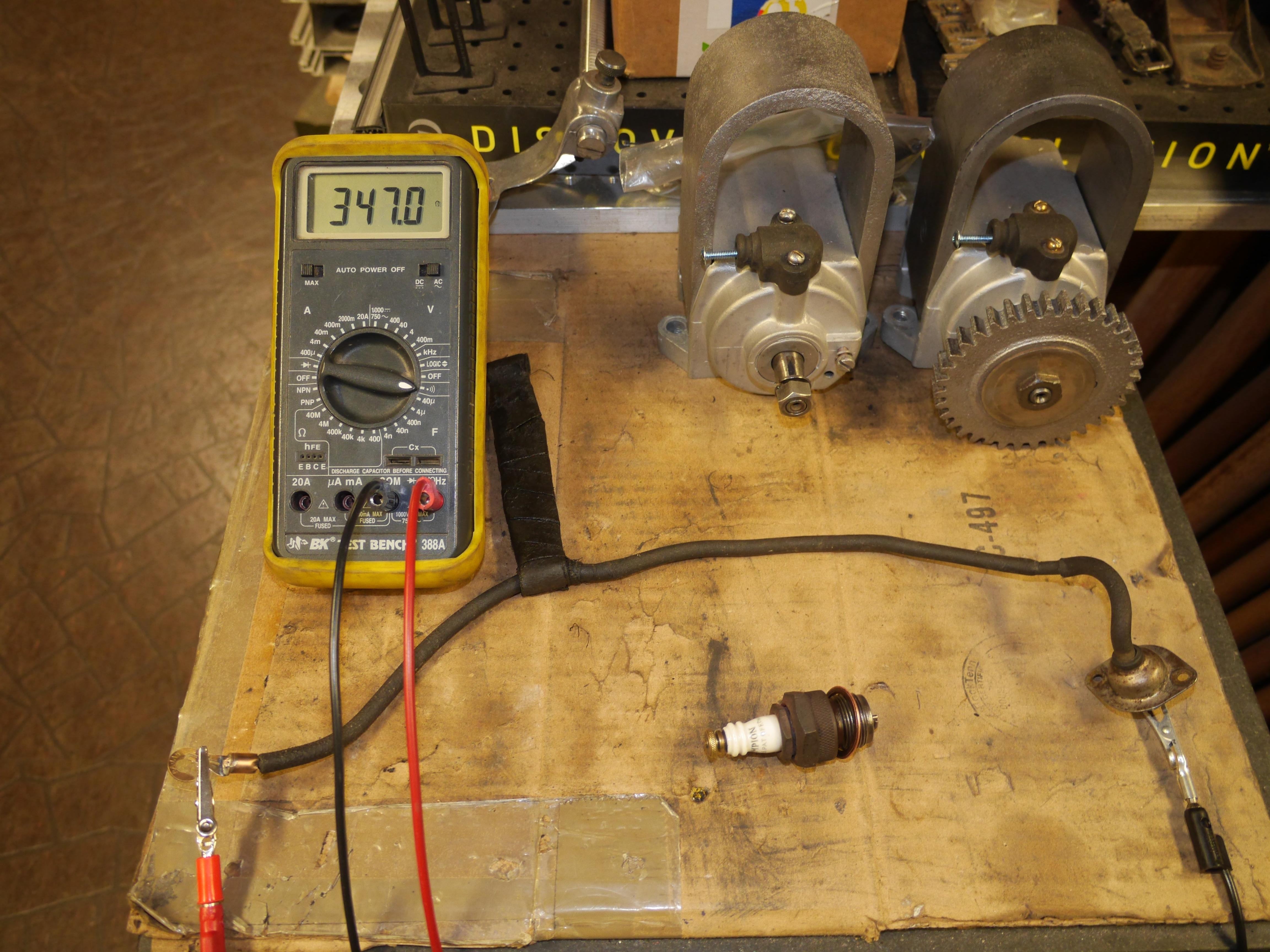
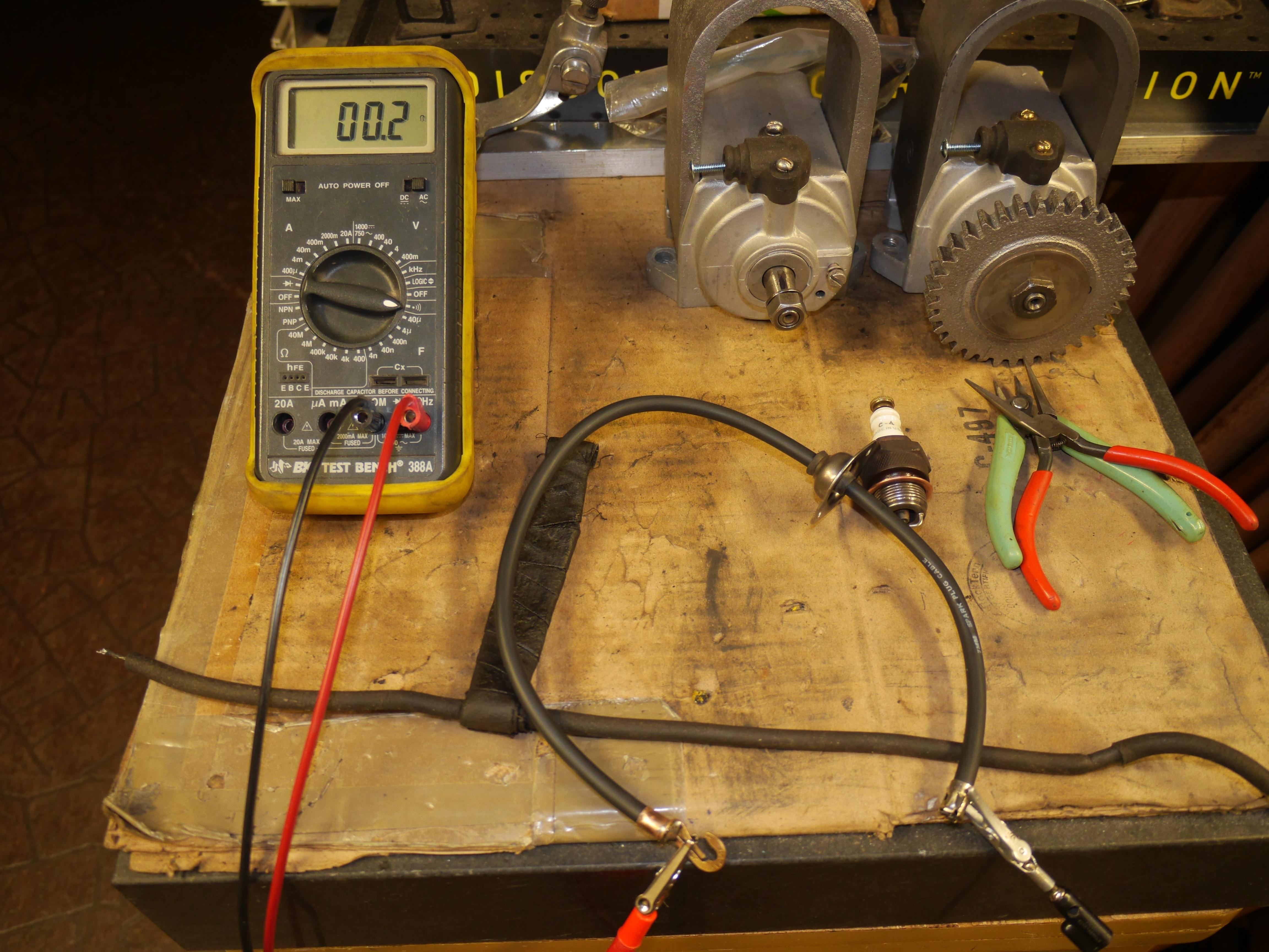
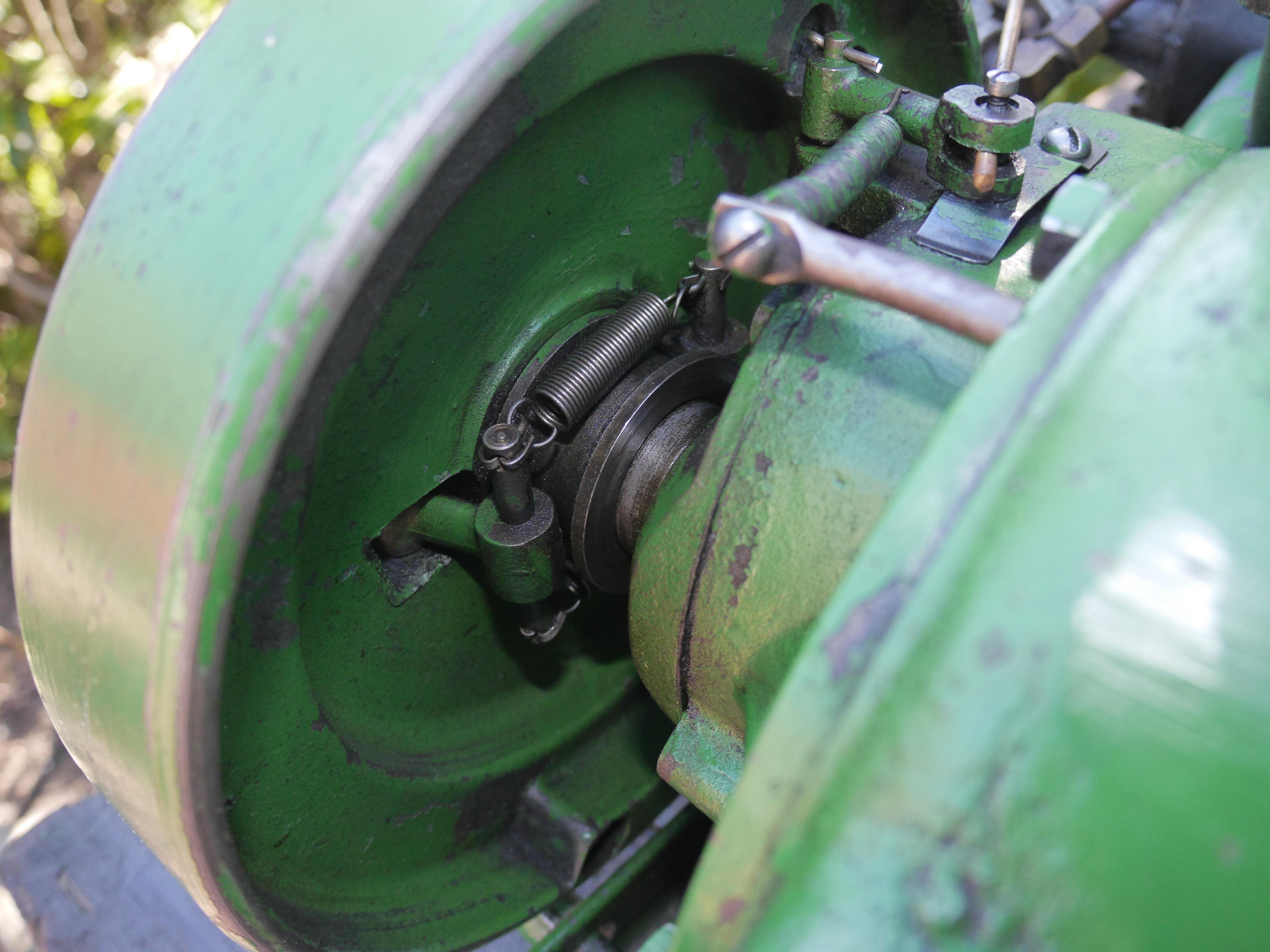
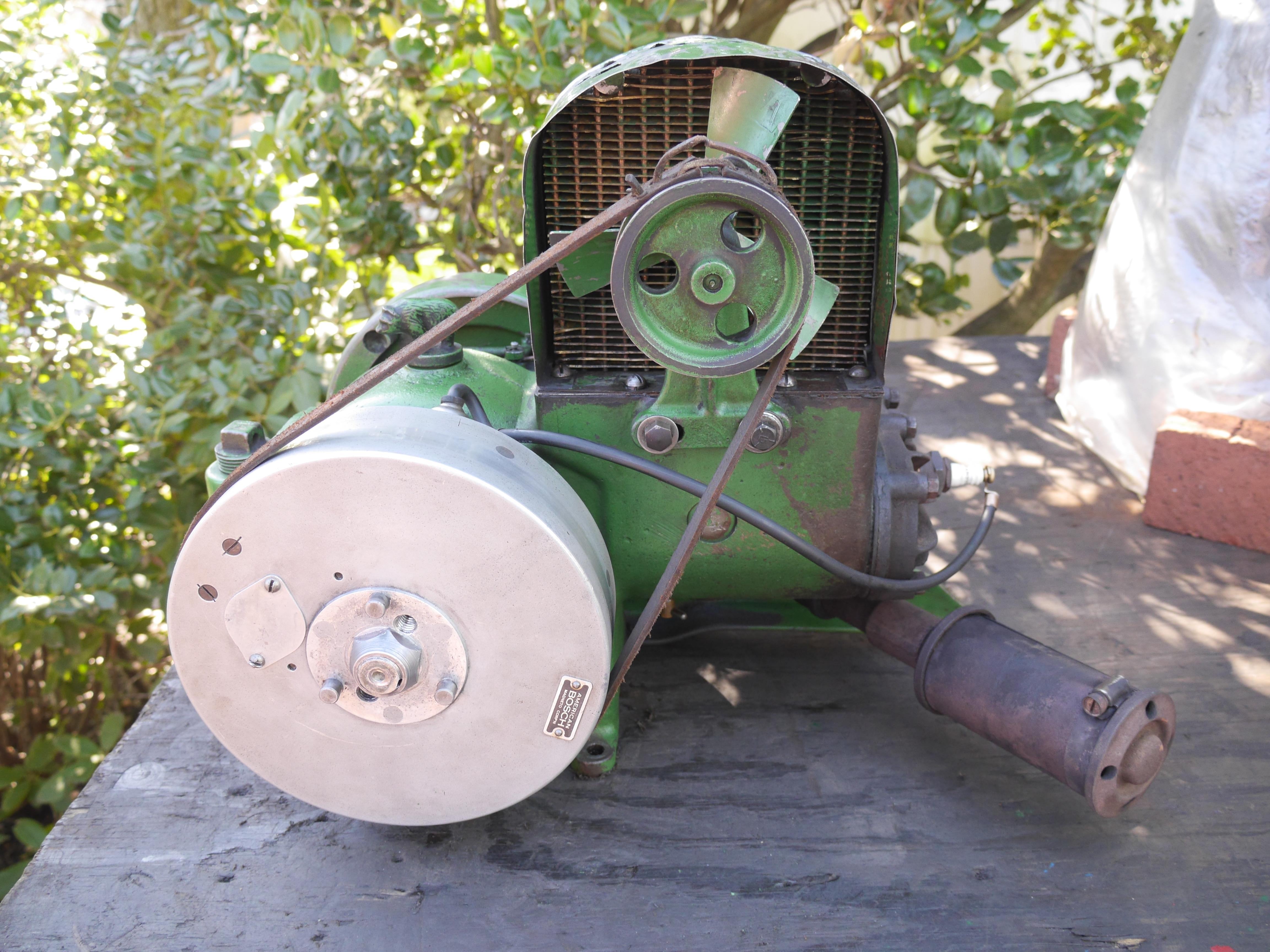
With the transmission off of the mower, I took this opportunity to pull the American Bosch magneto flywheel. This is normally a pretty simple procedure, but this time around the flywheel gave up quite a fight. Someone put too tall of a key in place, wedging the flywheel in too tight. Thankfully this did not damage the flywheel in any way. It took quite a few attempts to file the key to the appropriate dimension for proper fitment. Underneath the flywheel was a bit dirty as to be expected, but everything looked surprisingly nice. The points showed a tremendous amount of wear, which I attribute to a loose spring on the rotating point contact. Tightening up the point spring allowed me to line up the points for proper fitment. It took a lot of dressing with various stones before polishing with a diamond stone and an emory board. I removed a lot of material! The good news is that almost all of the material I removed came from the stationary point which is replaceable,…., that is if one can be furnished. With the points operating like they should, I test fit the flywheel and I had no spark. I traced the issue down to a bad high tension plug wire. The high tension plug wire was shorting to ground at the metal retention clip on the ignition tower. A new plug wire made a world of difference. With the points gapped to 0.020” I had a nice hot spark. I do not have any specs for this engine, so I am putting my experience with small air cooled engines to the test. So far so good!

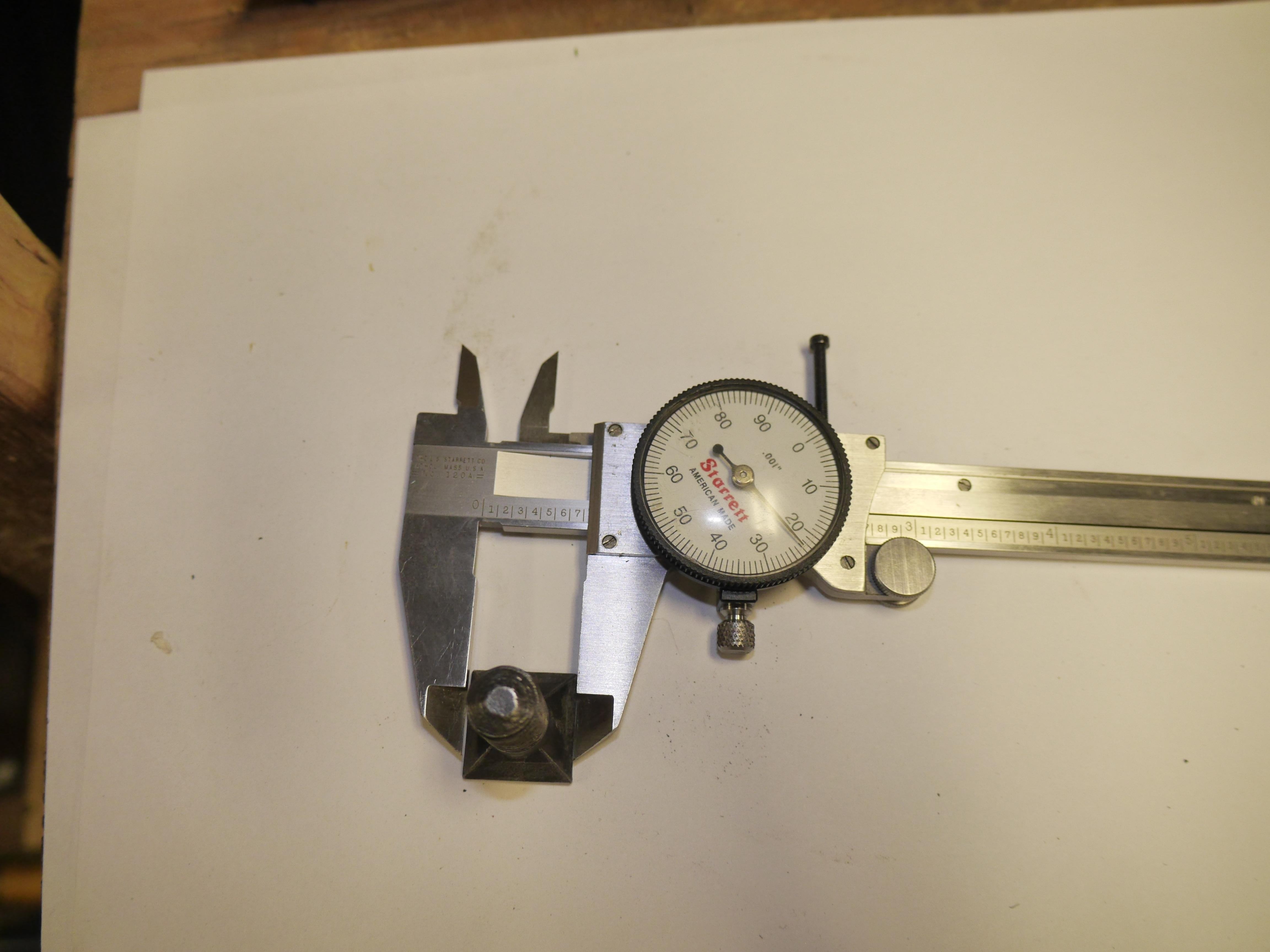
Design Decisions
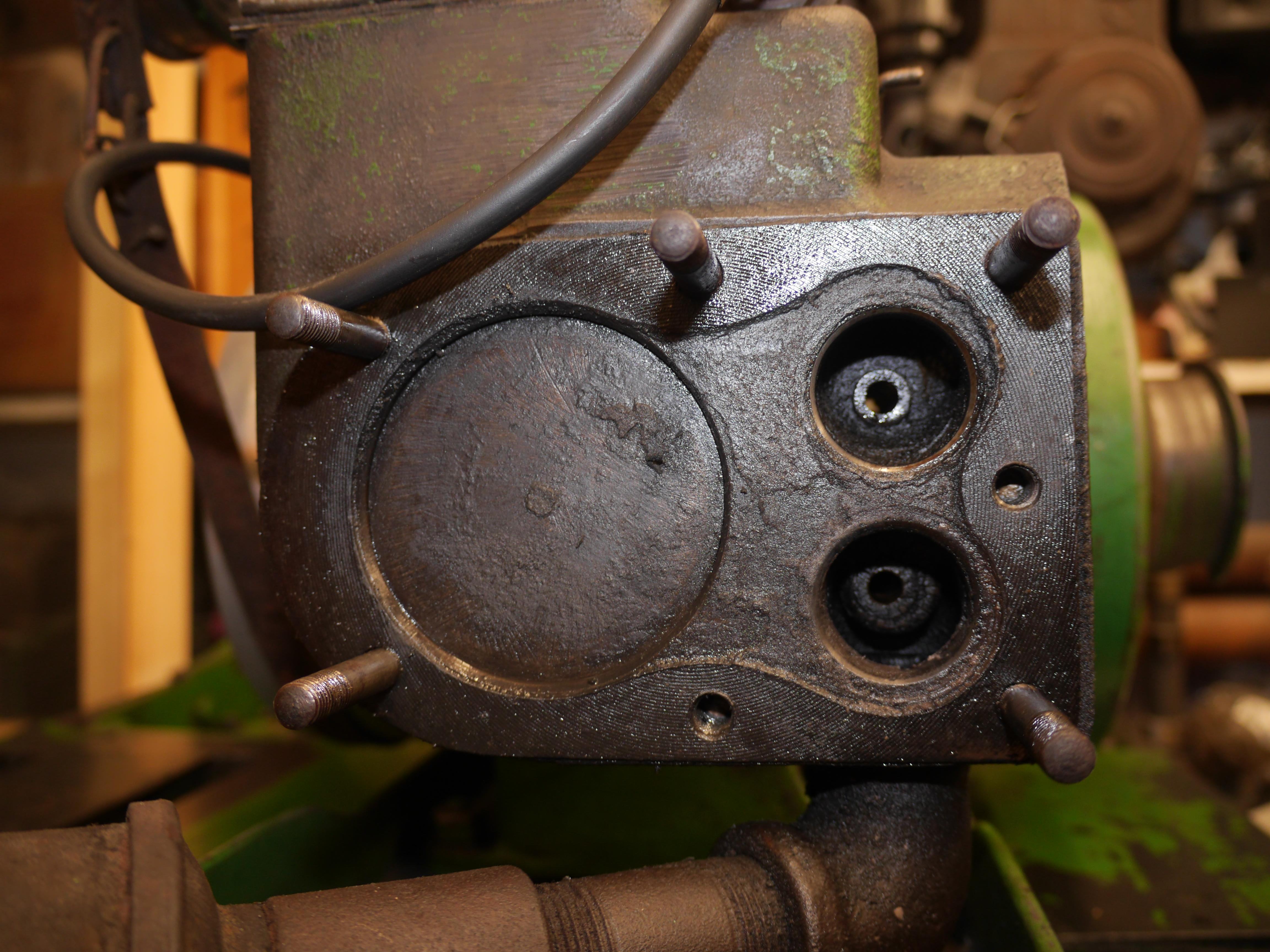
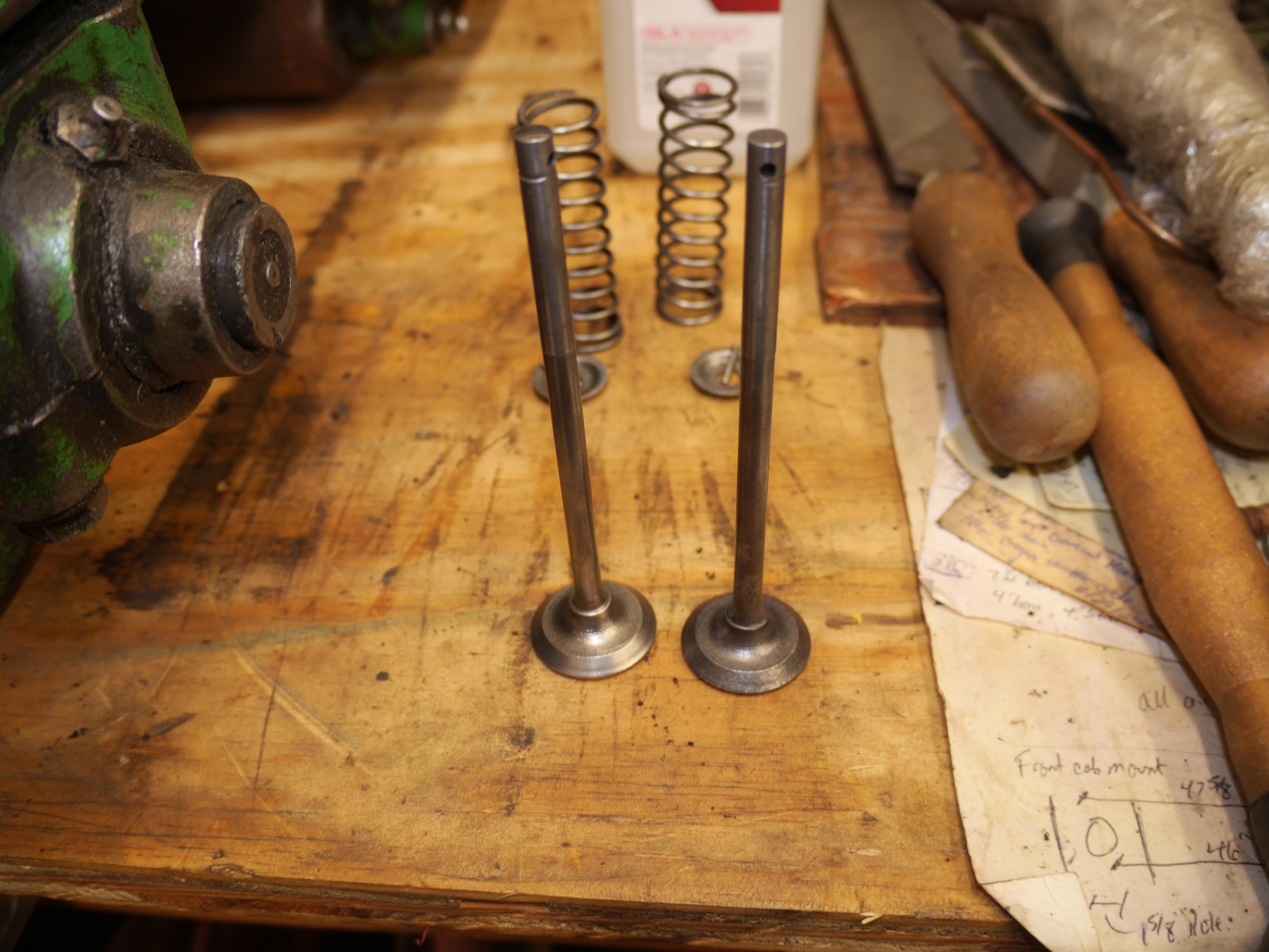
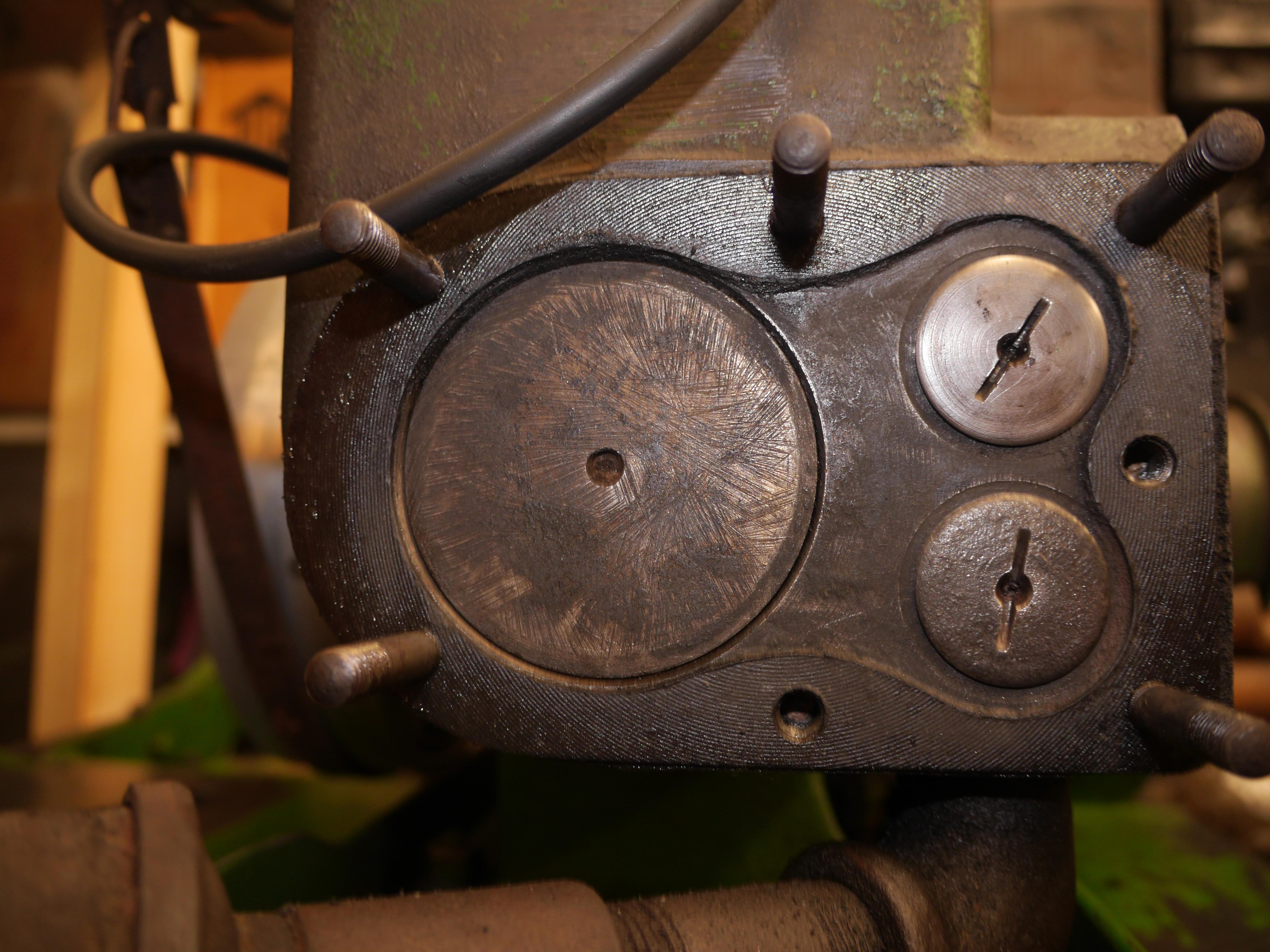
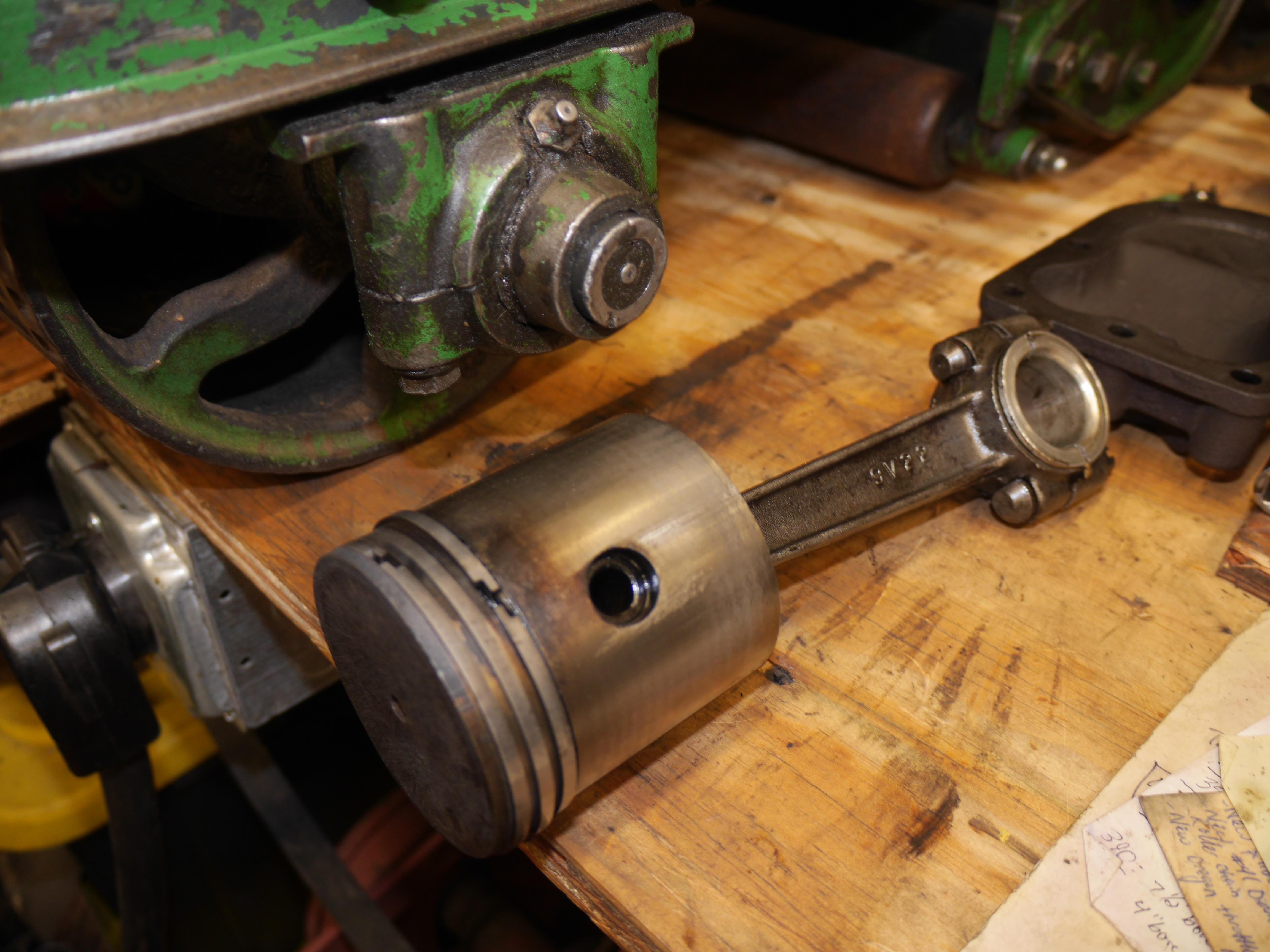
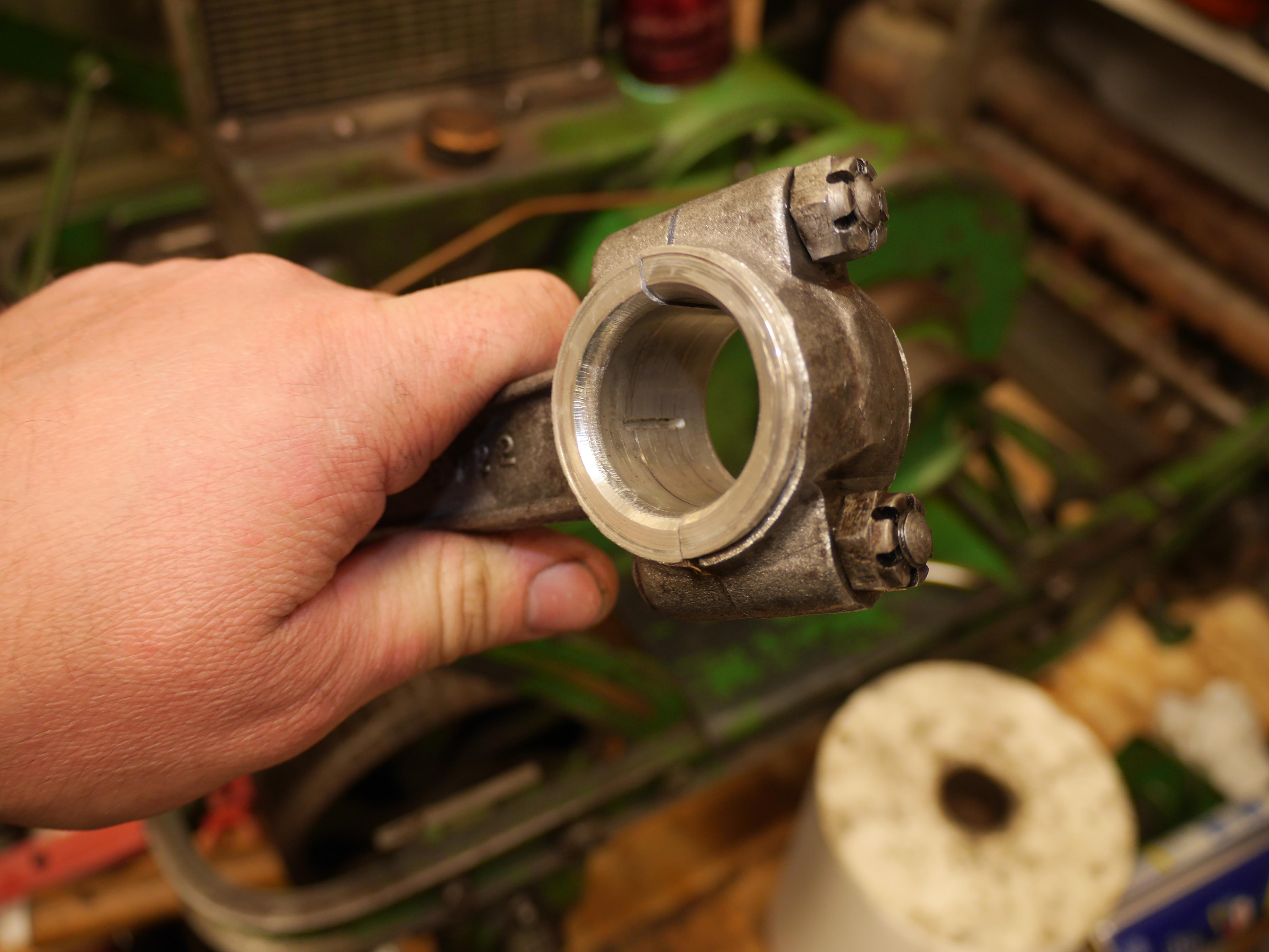
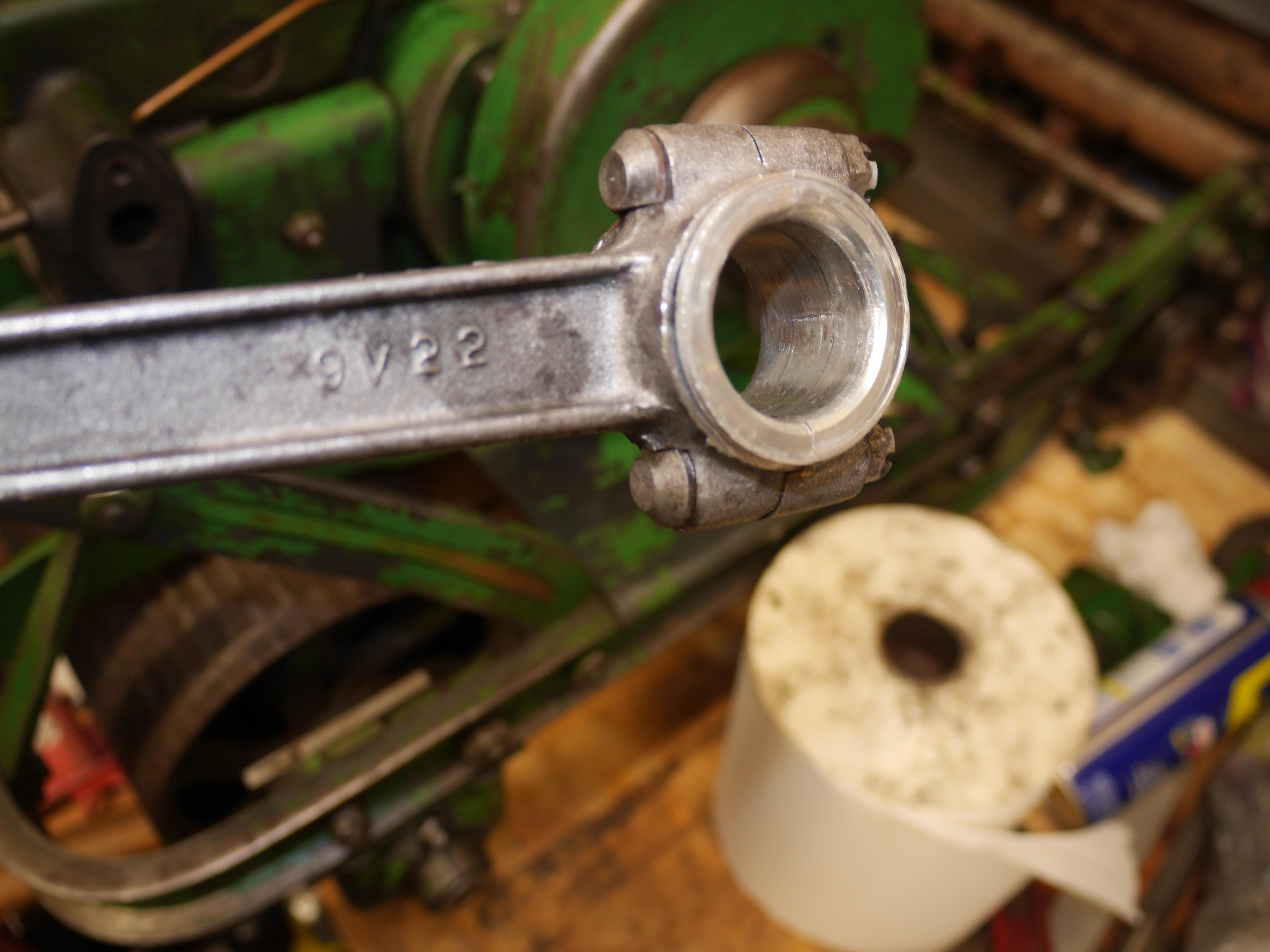
At this point, I decided to just dive right into the engine and see what I was dealing with. I removed the 1970s Carter model N carburetor, the valve cover and the cylinder head. Everything looked okay, just dirty. The intake valve was loose, and the exhaust valve was a bit sticky. After wire brushing the valves I discovered that the intake valve stem was worn 0.011” undersized. That tells me that this engine ran a long time without an air filter in place. After lapping the valves I test fit them in the block and they moved nicely in the bronze valve guides. Valve lash seems excessive, but I have no specs from Coldwell. I measured 0.012” of clearance on the intake valve and 0.024” on the exhaust valve. Since this is a slow speed water cooled engine, I imagine the specs should be closer to 0.006” for the intake and 0.008” for the exhaust. I did not see the need to cut the valve seats that much to correct the valve lash, so I let it be. Upon reinstallation of the valves I discovered that the upper spring retainers were missing for both the intake and exhaust valve springs. I will have to machine some new ones in the future. With the valves clean, I used a wood spudger to remove some of the gunk from the top of the piston. Wiping the piston off removed a lot of heavy deep file and grinder marks which had me very concerned. I initially thought that the grinding was from the piston dome being blown out and welded back in place. This did not sit well with me, so I removed the piston and rod assembly. To my surprise the piston looks brand new, there is hardly a scratch in the skirt anywhere. There was no sign of the piston ever being welded judging from the underside of the piston dome. What a relief! The removable poured Babbitt inserts looked great and the crankpin appears to be in great shape. I put the piston, rod, and Babbitt in my ultrasonic cleaner, for an hour while I honed the cylinder. Cylinder honing did not take all that long, but cleaning the cylinder and crankcase did! I only lightly honed the cylinder with my Sunnen junior rigid body hone. I noticed that there is a bit of a wave in the cylinder, which is to be expected with horizontal cylinder engines. I felt that there was no point in trying to straighten the cylinder, so I stopped honing after about one hundred strokes. There is enough cross hatching in the cylinder at 2.753” that the rings should seal up nicely. The pitting at the base of the cylinder has me a little concerned, but prodding the pits with a pin revealed that the pitting was not deep enough to enter the water jacket. The honing knocked off whatever burrs might have been in this area. Judging by the flawless piston skirt, this pitting did nothing other than hold some additional oil.


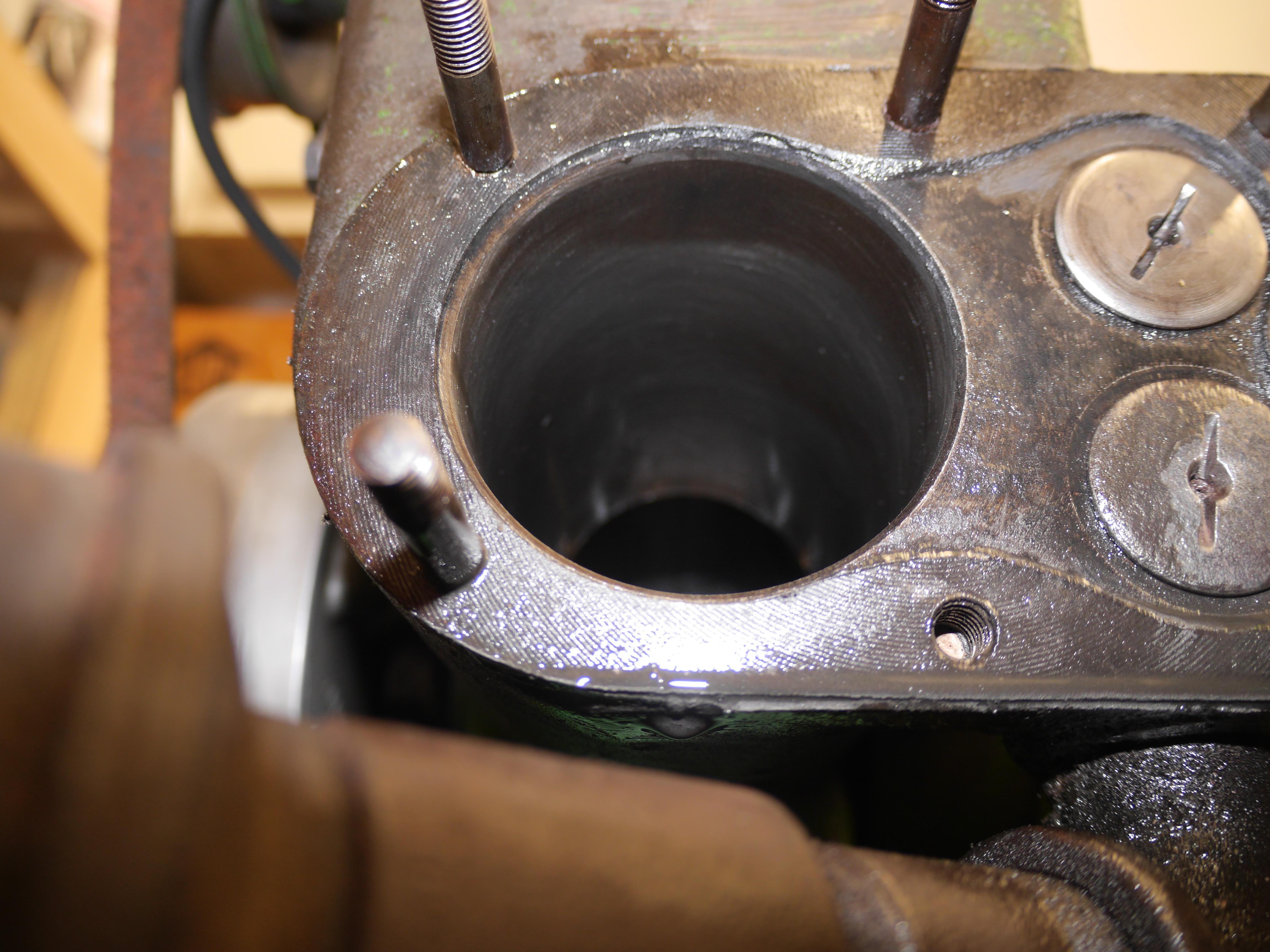
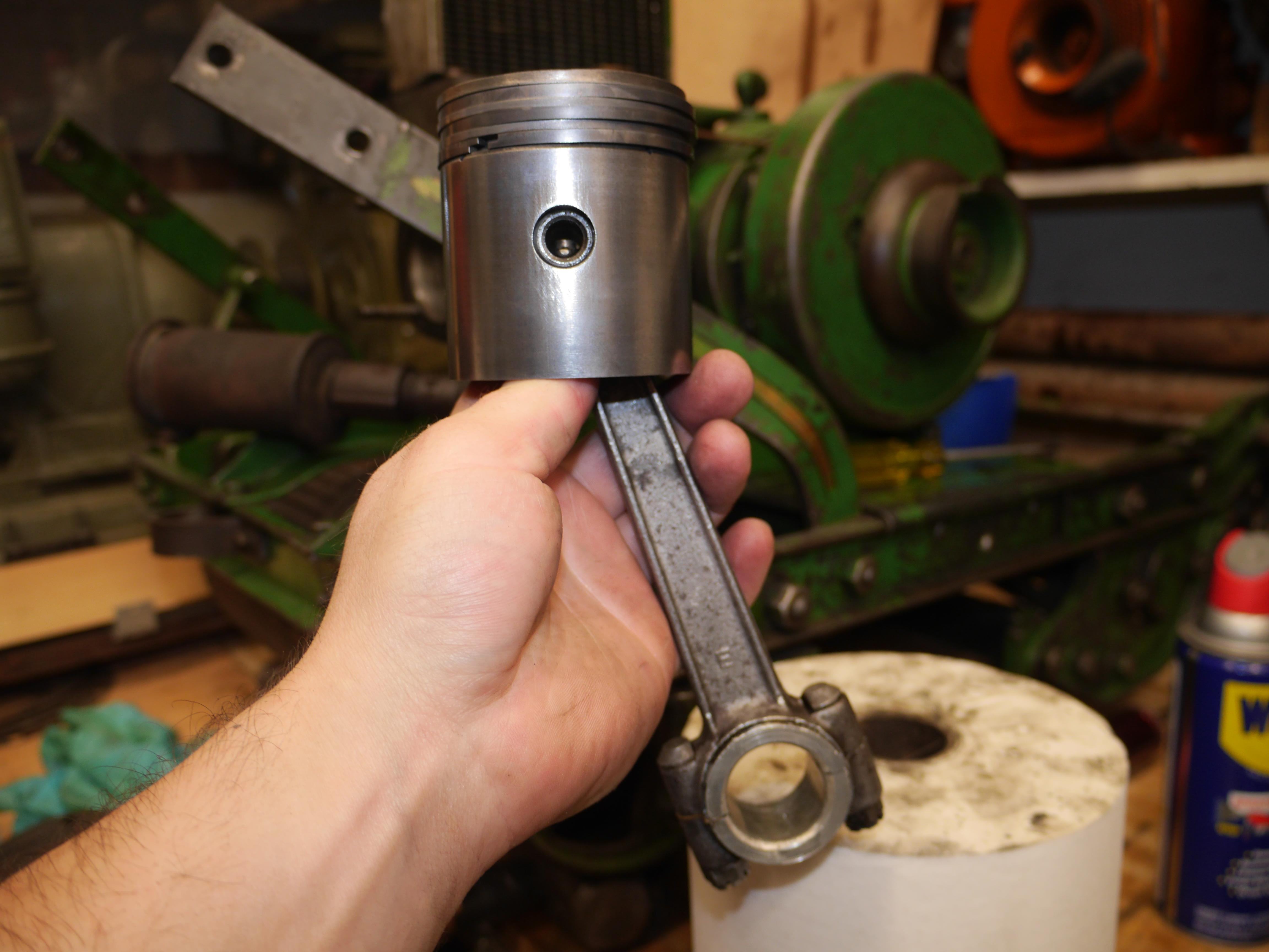


After any form of honing it is imperative to remove any and all abrasive slurry from the cylinder and crankcase. With such a small service port in the crankcase it took quite a while to scrub the inside of the crankcase clean. Once my alcohol soaked paper towels came up clean, I liberally coated the piston with assembly lube and slipped the piston into the cylinder. As careful as I was, the loose fit rod bolts fell out. It took me over two hours to successfully install the connecting rod. The initial fit only took about twenty minutes, but it did not feel right. The lower Babbitt shell did not fit right in the rod cap. After taking the shell back out, I discovered a small burr on the rear lip which was preventing the insert from bottoming out in the cap. Upon reinstallation, I still did not like the fit of the rod. I snugged the rod nuts down and backed them off 1/6th of a turn. Turning the flywheels felt wrong. Back apart, I knocked the sharp edge off of the Babbitt shells with my needle file. I happened to notice a small burr on the side of the Babbitt shell which was binding on the rod cap. This time everything felt right. I snugged down the rod bolts to as tight as I could make them with a six inch ratchet. Then I backed the nuts off until the cotter pin holes lined up. I ended up backing the nuts off 1/3rd of a rotation. The rotating assembly felt right, and I could not feel any slop in the bottom end. With the cylinder head off and fresh SAE30 oil in the crankcase I cranked the engine over for five minutes at operating speed with my drill. I watched the oil pump work, stopping periodically to check the temperature of the rod cap. Everything looked and felt right. I buttoned up the breather, and mounted the cylinder head. Compression came up tremendously with a fresh valve job and a freshly honed cylinder. I can hear the breather working, and you can feel the compression it has. It actually seems to have more compression than my other cub. I do not have a compression gauge adapter for a 7/8” spark-plug, so you will have to trust me. With compression, ignition, and some fuel it should run!


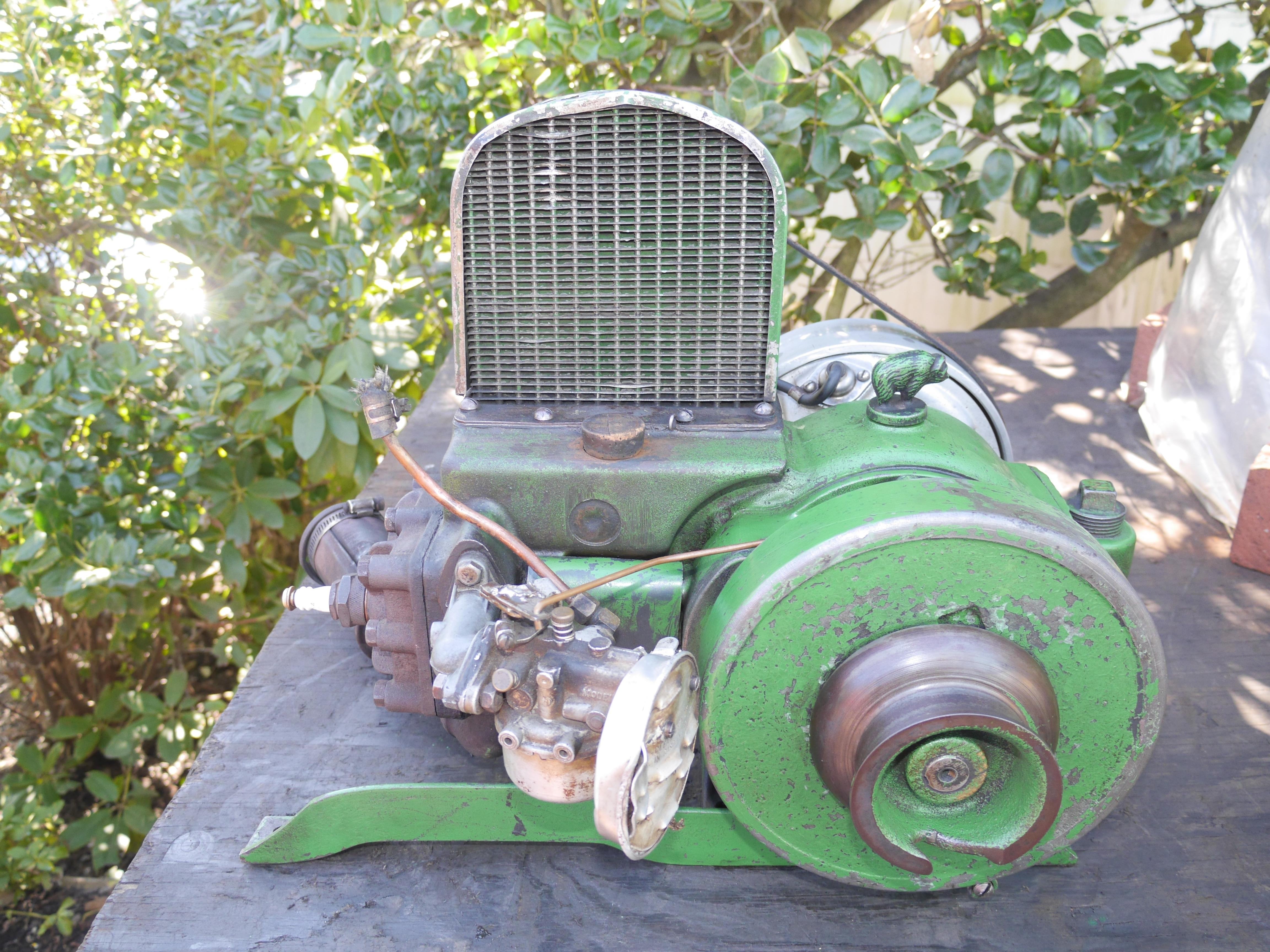
Today the 1931 Coldwell Cub roared to life for the first time in probably forty years. It started without any hesitation and ran as perfect as it could on a spray bottle carburetor. This is a 1-1/2hp engine at 1200rpm. It has a 2-3/4" bore and a 3" stroke, with 292cc displacement. I ran the engine a total of 45 minutes today. I brought the engine up to operating temperature three times, flushing out the crankcase in between each heating cycle. Quite a lot of scale and rust came out of the water jacket on the first two rinses. Everything seems to be working like it should. After this 17 minute long video I removed the breather from the engine and measured 96*F on the rod bearing cap, the same temperature as the crankshaft. I would call this one a success. I cannot wait to see it run under its own power! I have the original Tillotson MS31D carburetor for this engine, but it is in sad shape. I have to machine a new oversize main fuel jet and idle jet before I can bring the carburetor back into operating order. I hope you have enjoyed the pictures and video thus far. It has been a long time coming. As long as we all pull thru this pandemic, it will be running and mowing again!

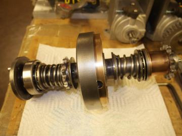
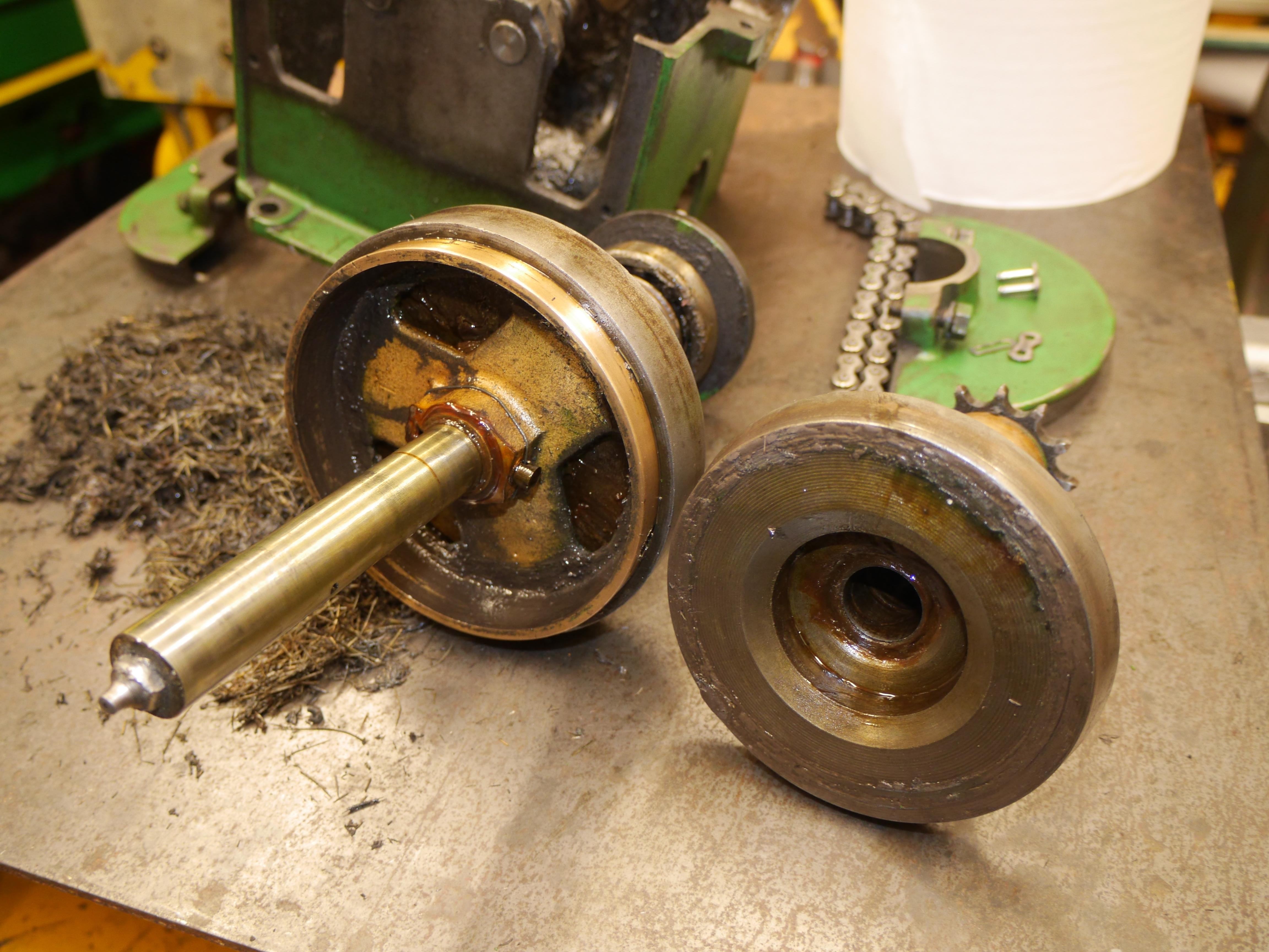
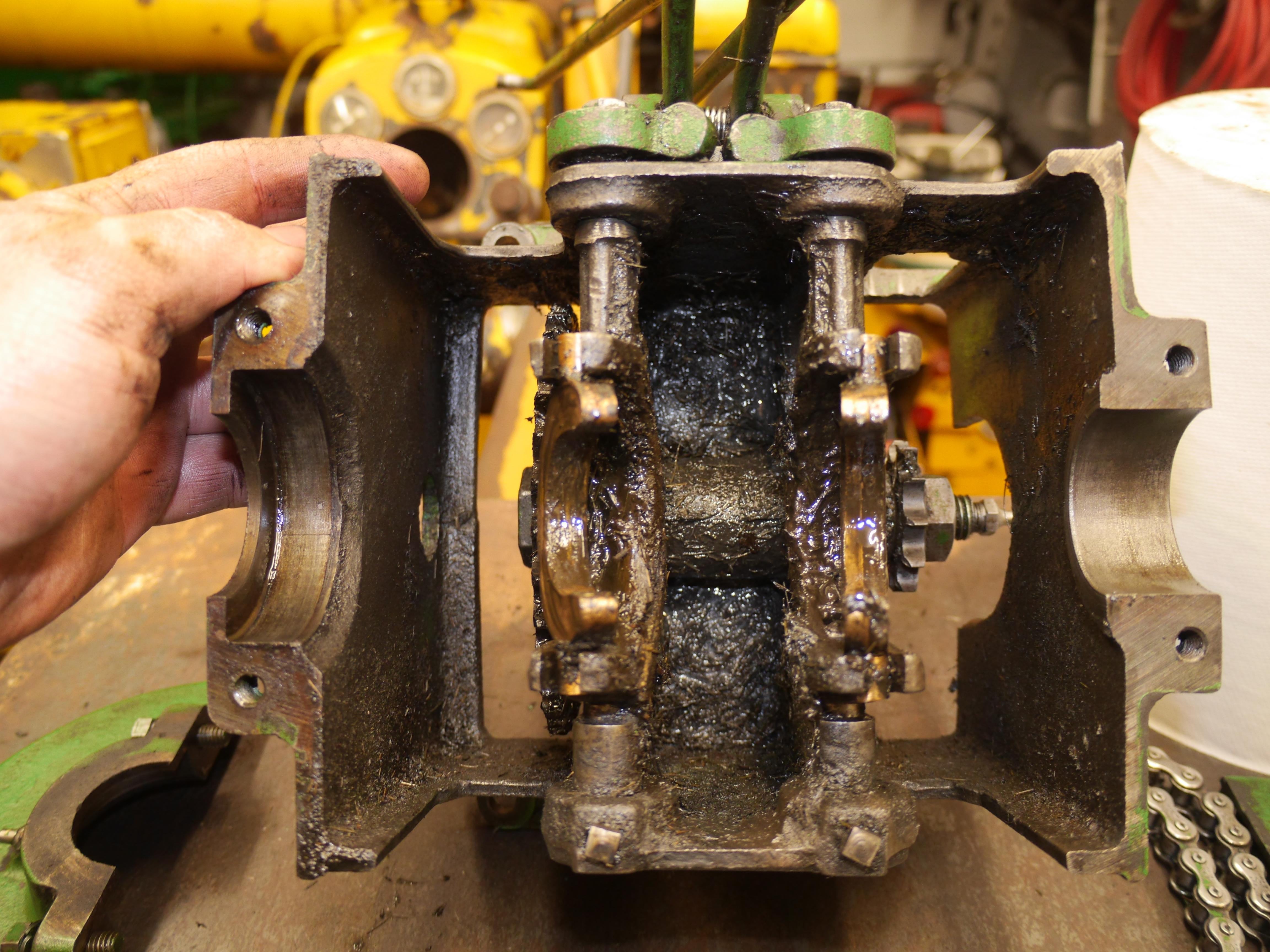
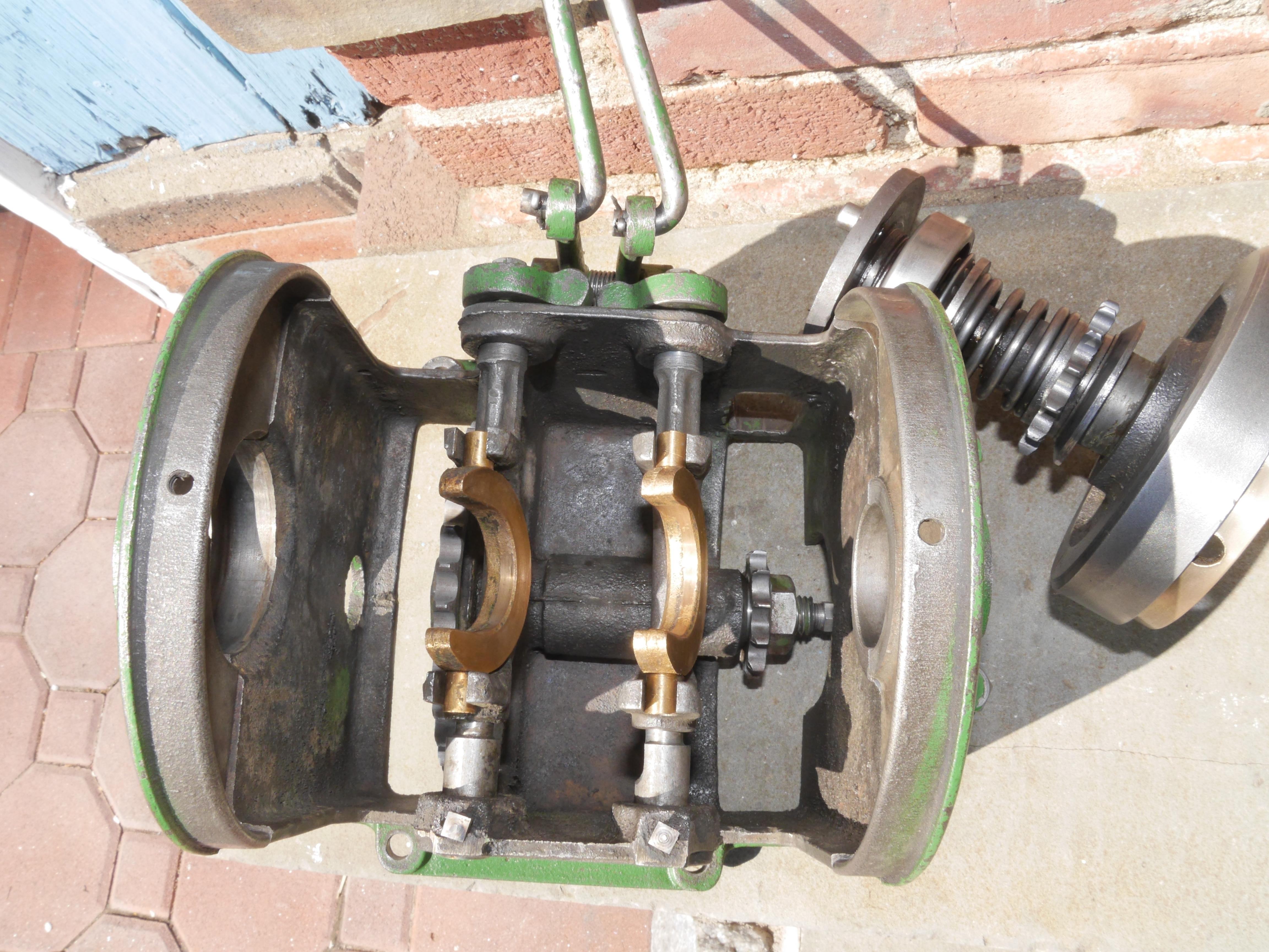
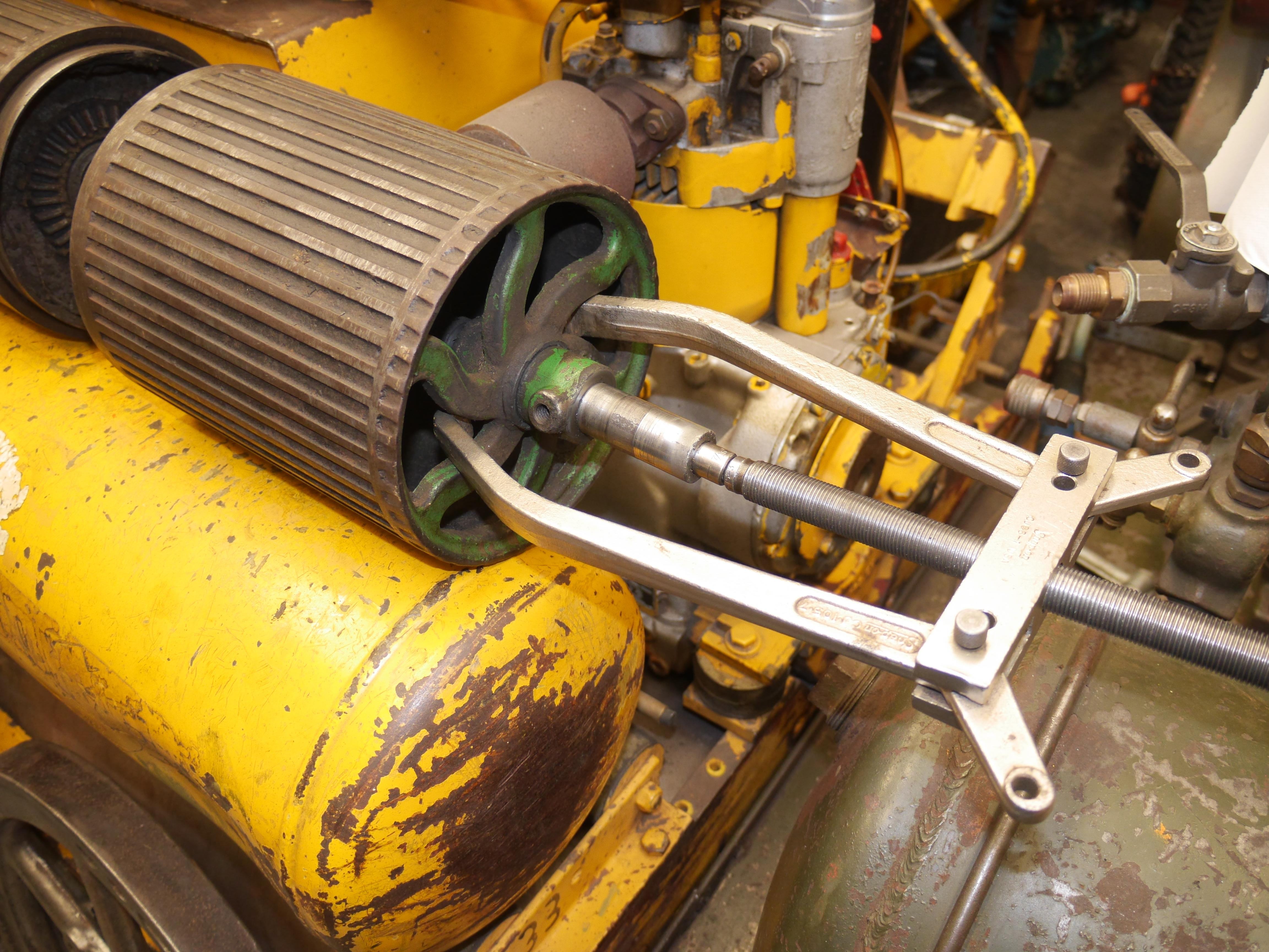
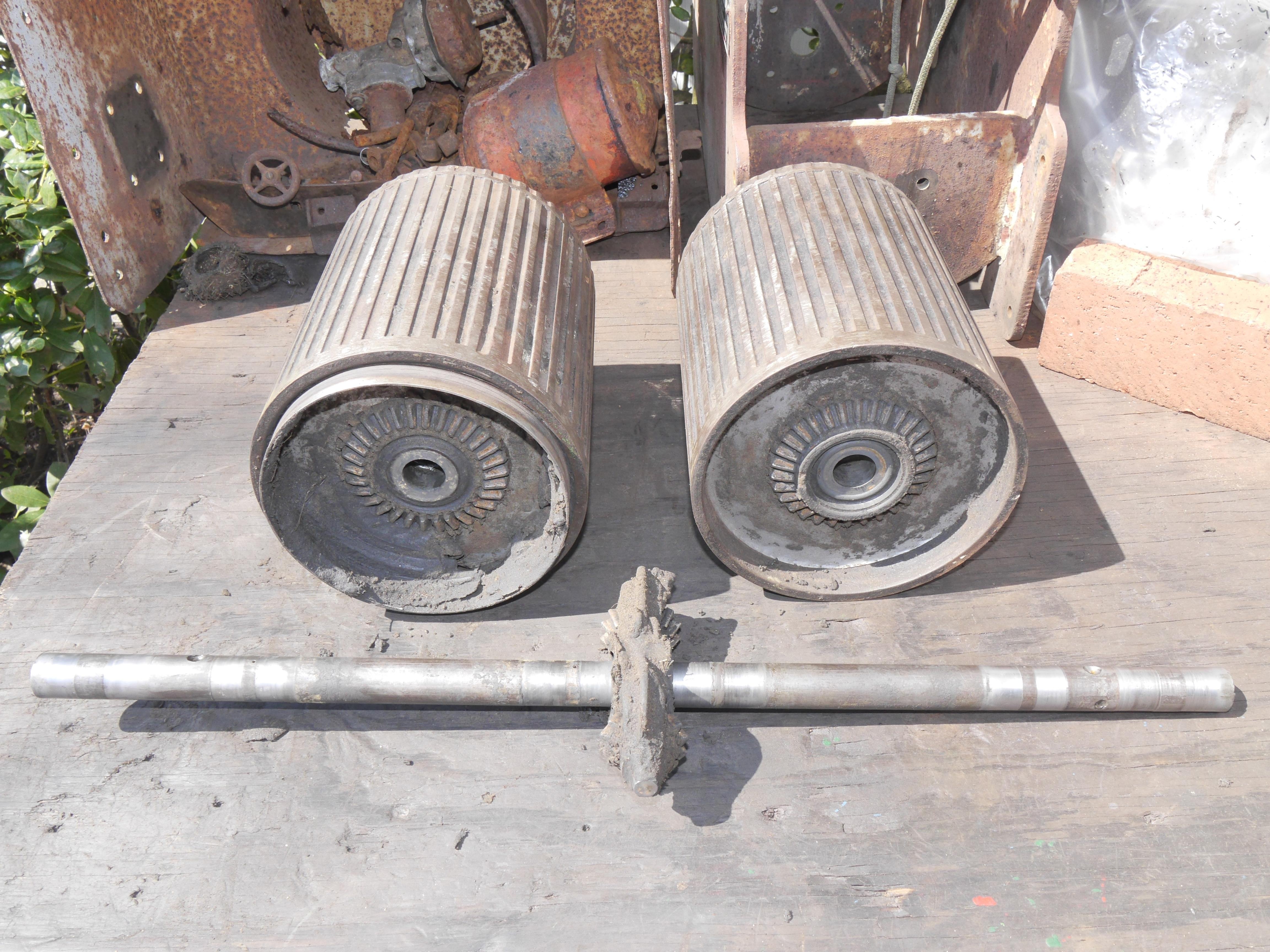
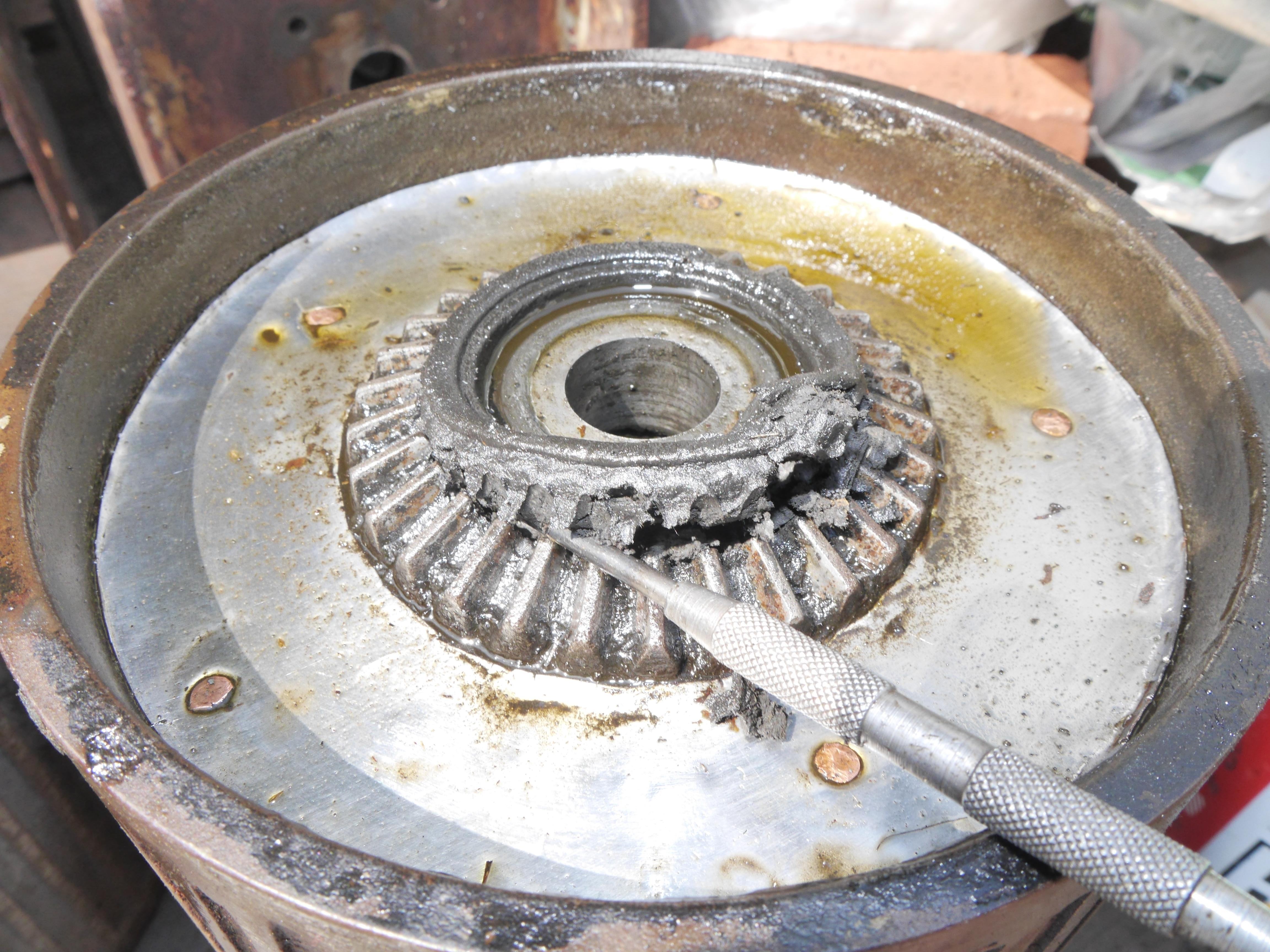
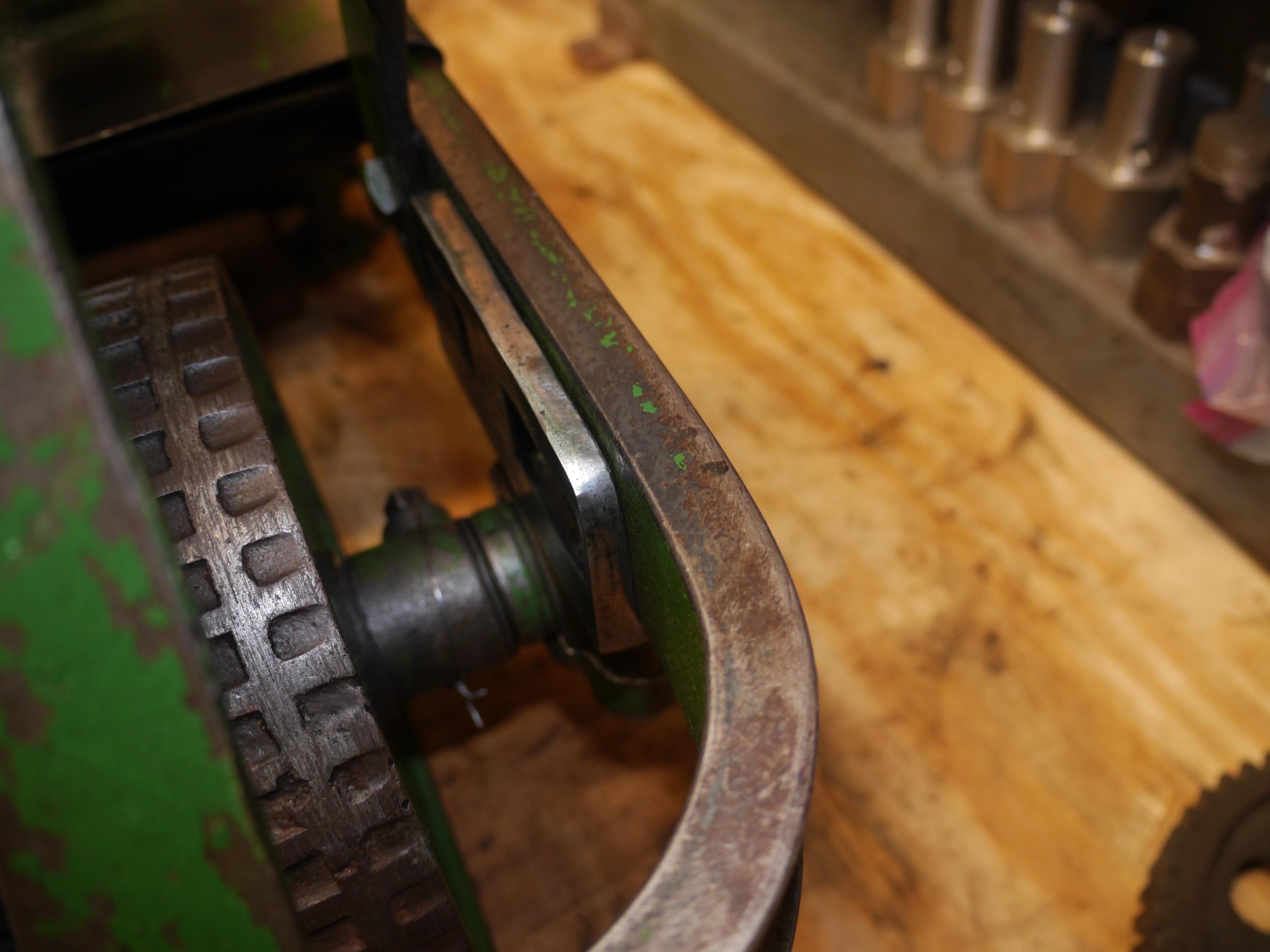
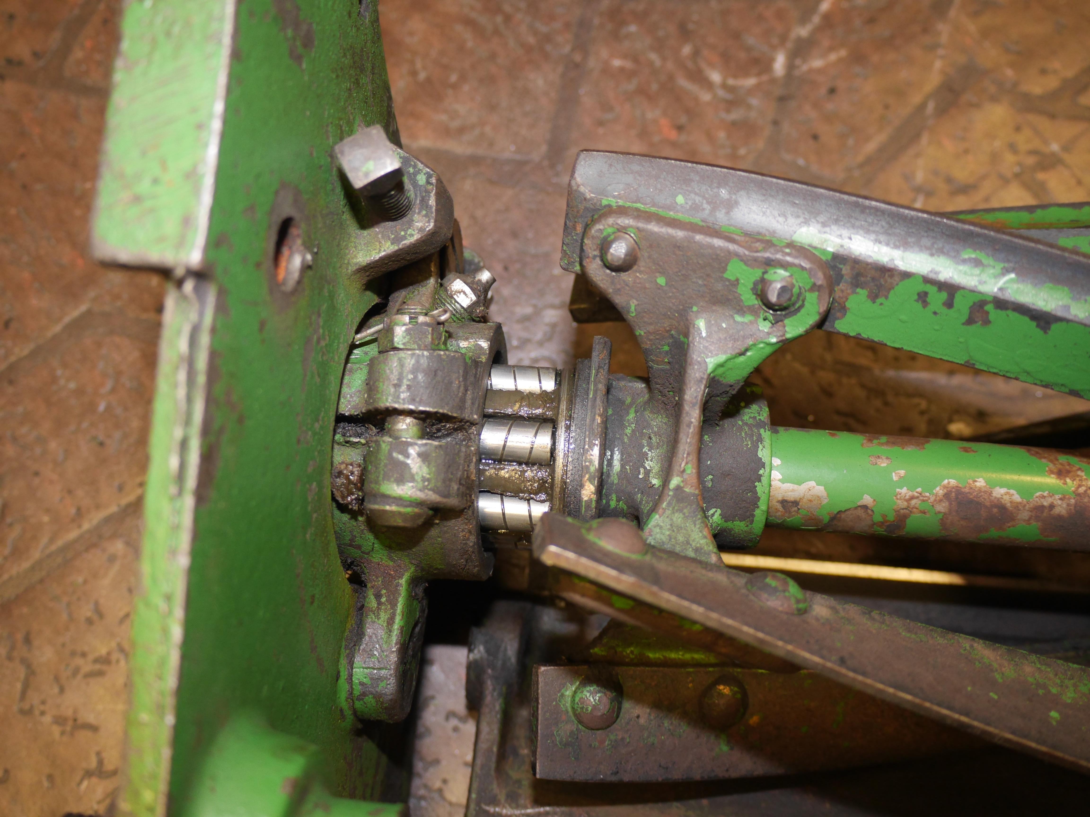
Since I am on a roll with the Coldwell mower, I continued onward with the differential drum drive. One of the rear bearing housings was broken and fish-plated back together, so now I had the opportunity to fix it. It took an entire day to clean all of the grease/grime from the drum. The petrified grease put up quite a fight and I had to use my puller to remove the drums from the axle shaft. Once everything was apart I spent hours scraping the hard packed grease out of every crevice. Rodding the hard grease out of the hollow axle took quite a while as well. It is amazing that the bearings are not worn more than they are with how little liquid lubricant there was. The rear bearings are actually quite neat the way that they are made. They are essentially cast iron pillow blocks with a centrally located grease fitting which more or less limits the movement of the inner swivel bearing. With everything clean, I took some critical measurements of the worn and raw segments of the axle and began re-assembling everything. With just 0.004" of wear on most of the bearing surfaces, there was no reason not to put the axle back into service. Using the lathe in back gear, I was able to test the differential before fully assembling the axle. It runs nice and smooth now, which should drastically help in maneuvering the mower. I thought you would like to see the differential drive in action.
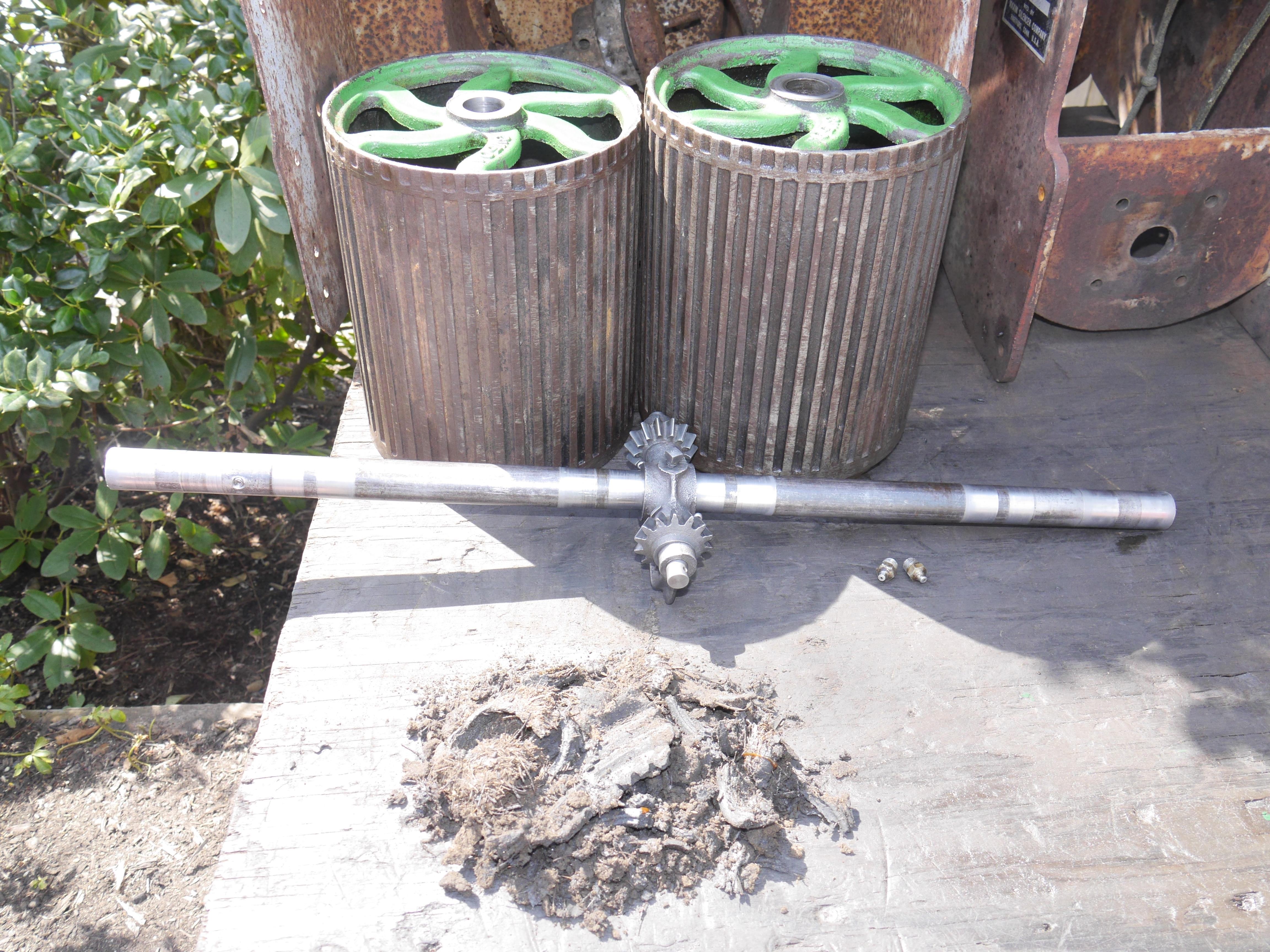
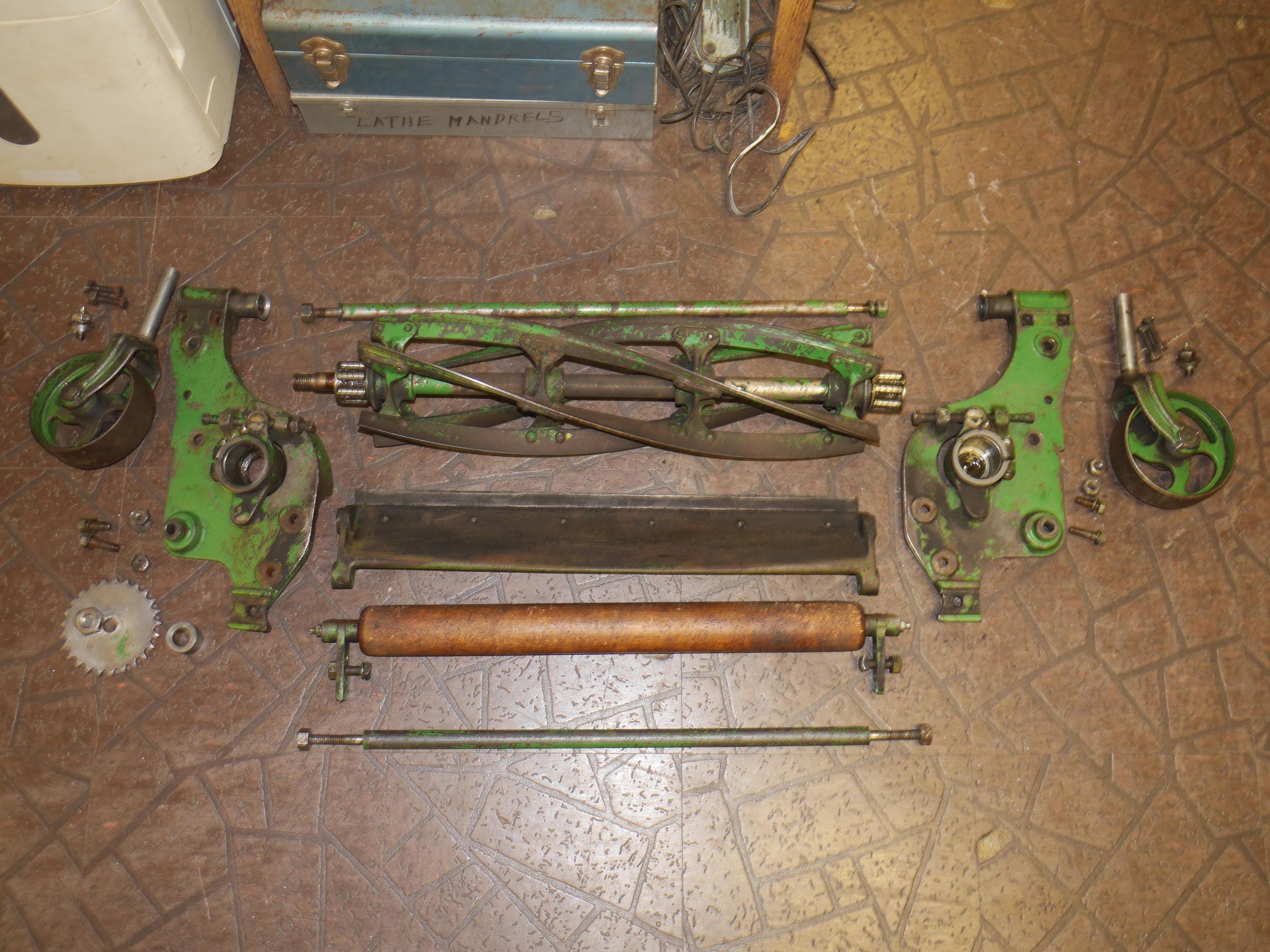
Disassembled:
Assembled:
I also added along some pictures of a neat old farm fix I discovered. Someone added some dirt shields to the drums made out of an old Texaco oil sign. I thought it was neat enough to leave it as a memento of its earlier life. How well it worked is unknown, there was still a lot of dirt and grime in the differential assembly. I am fairly certain that the drums on this mower have been replaced at some point since the ridges in the drums are deep and show virtually no wear.
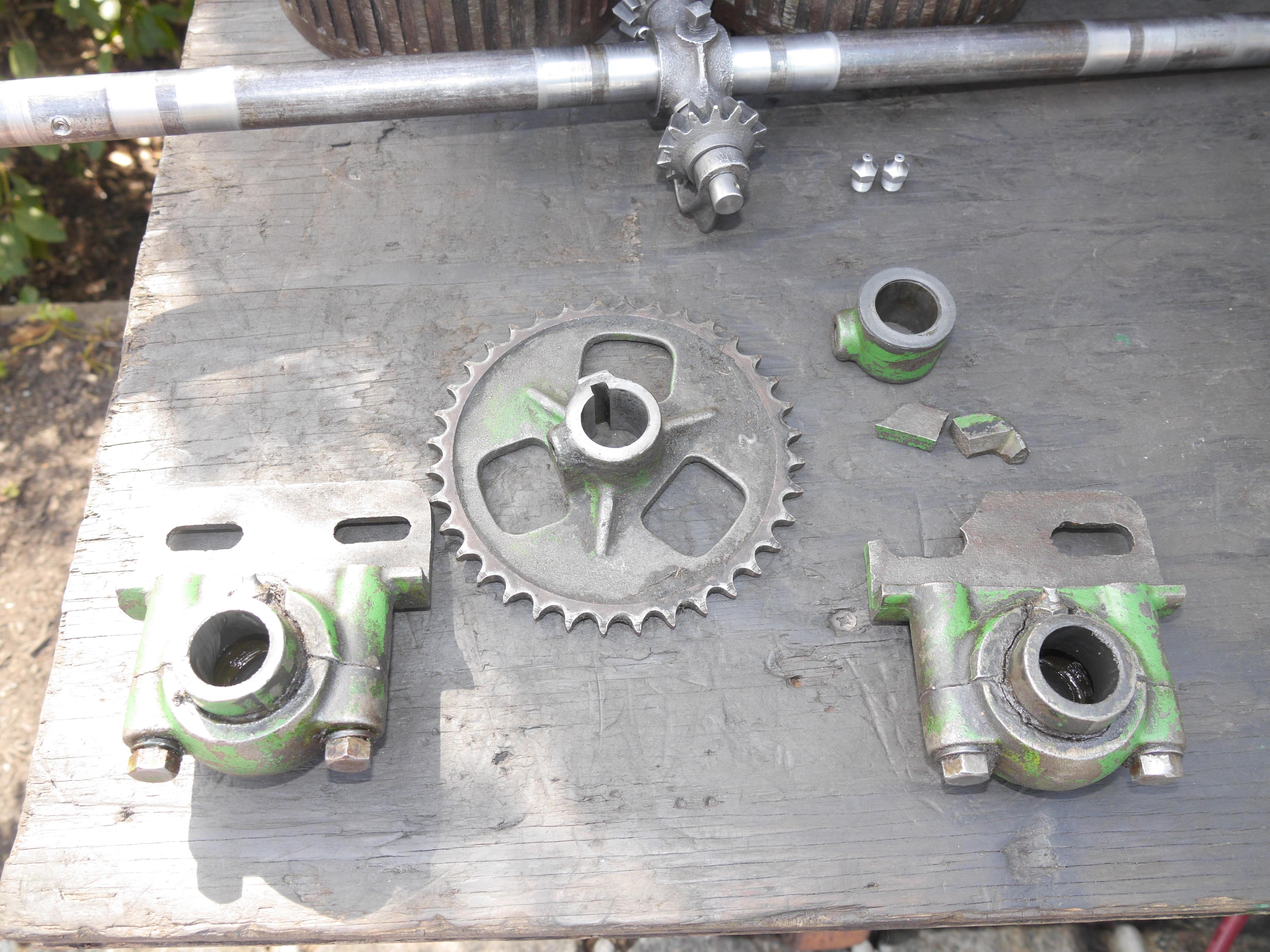
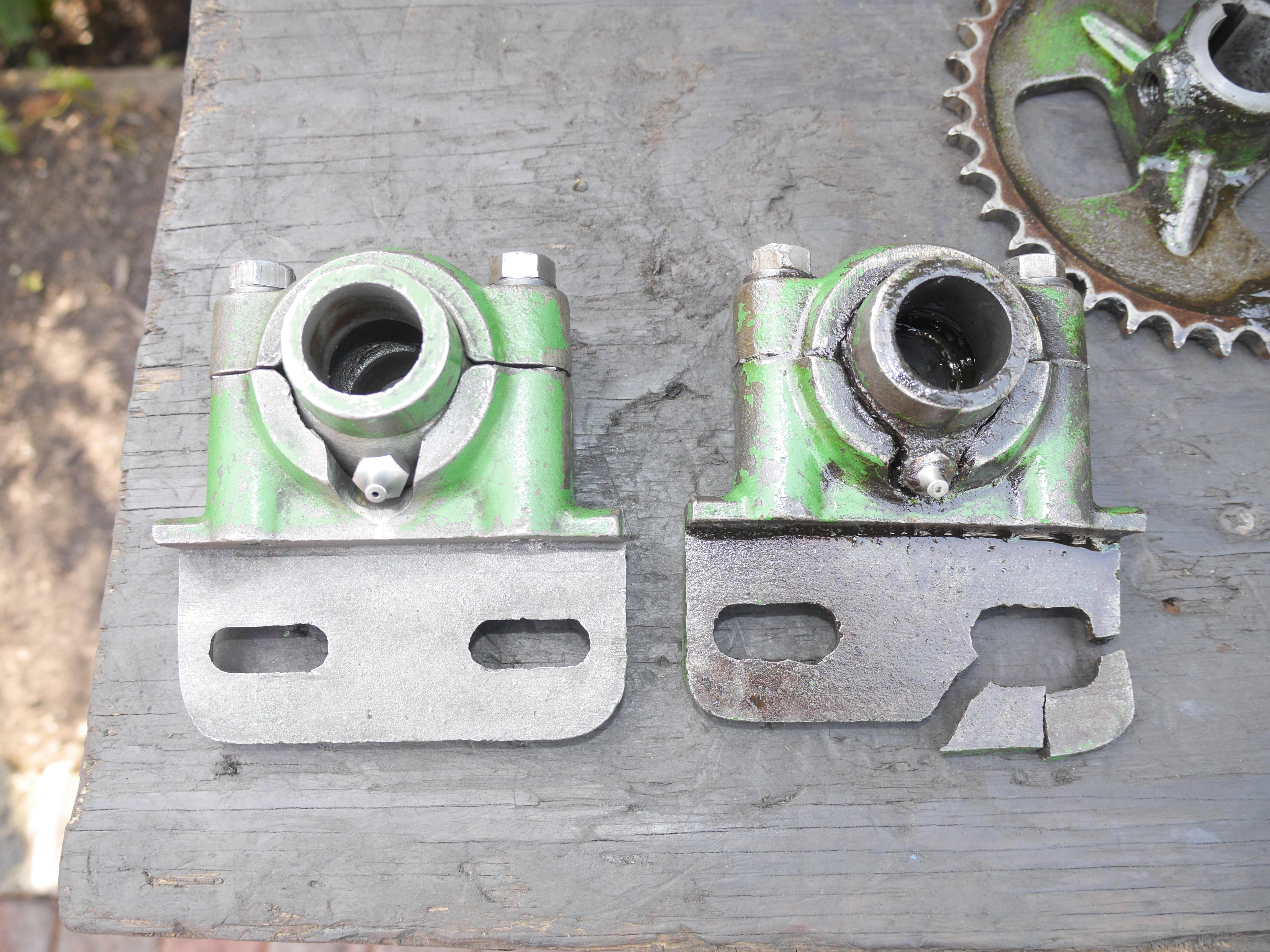
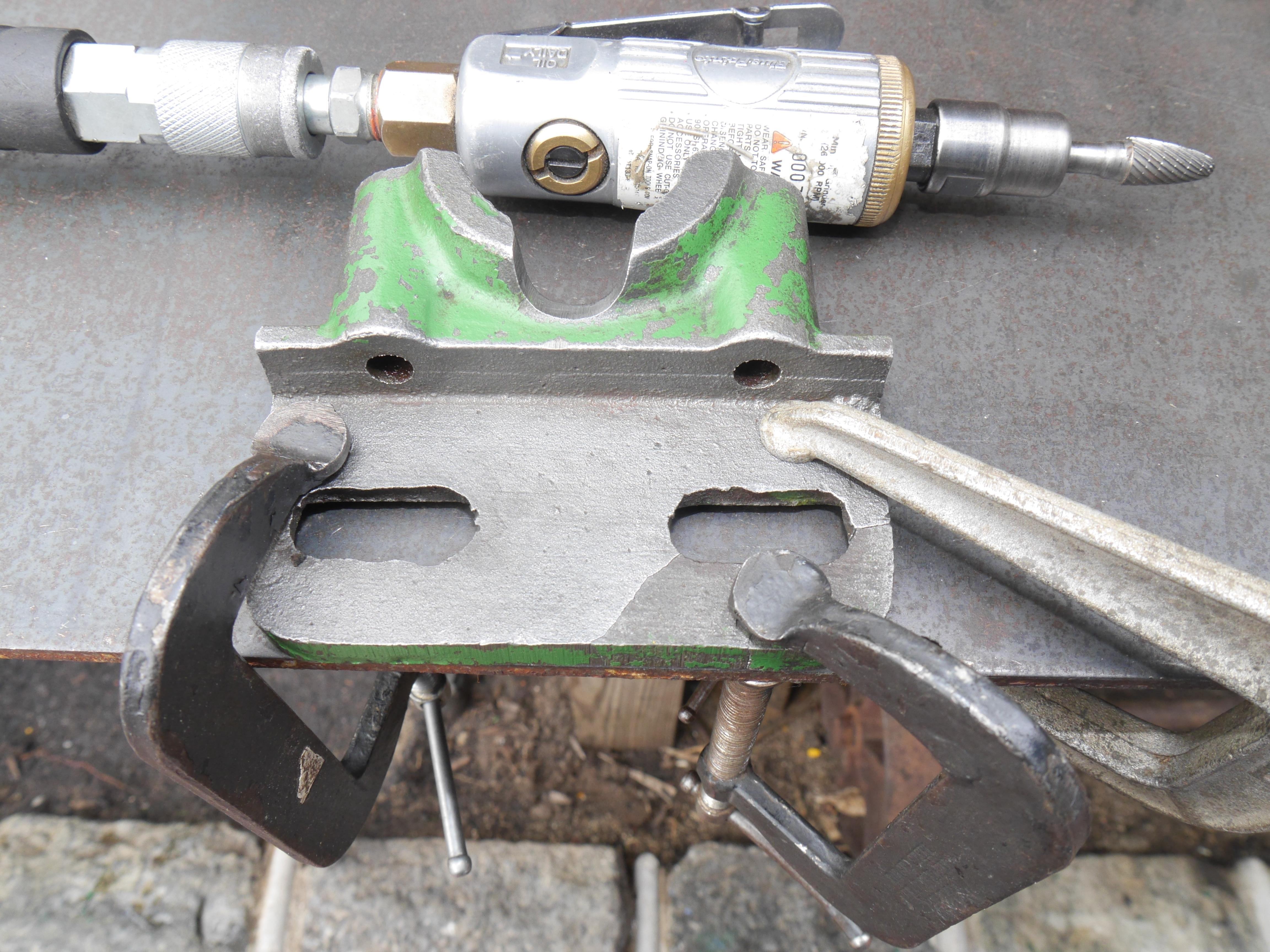
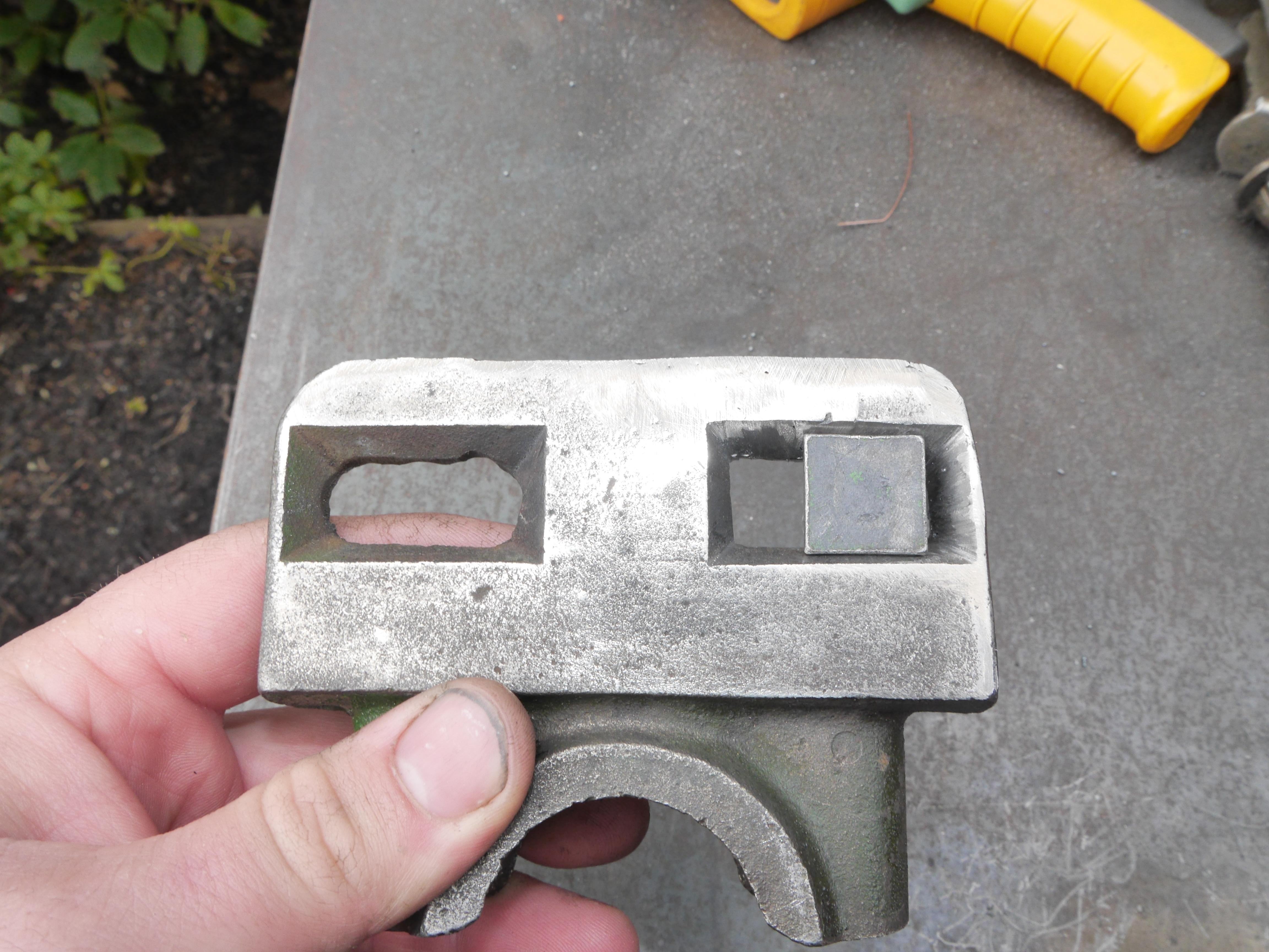
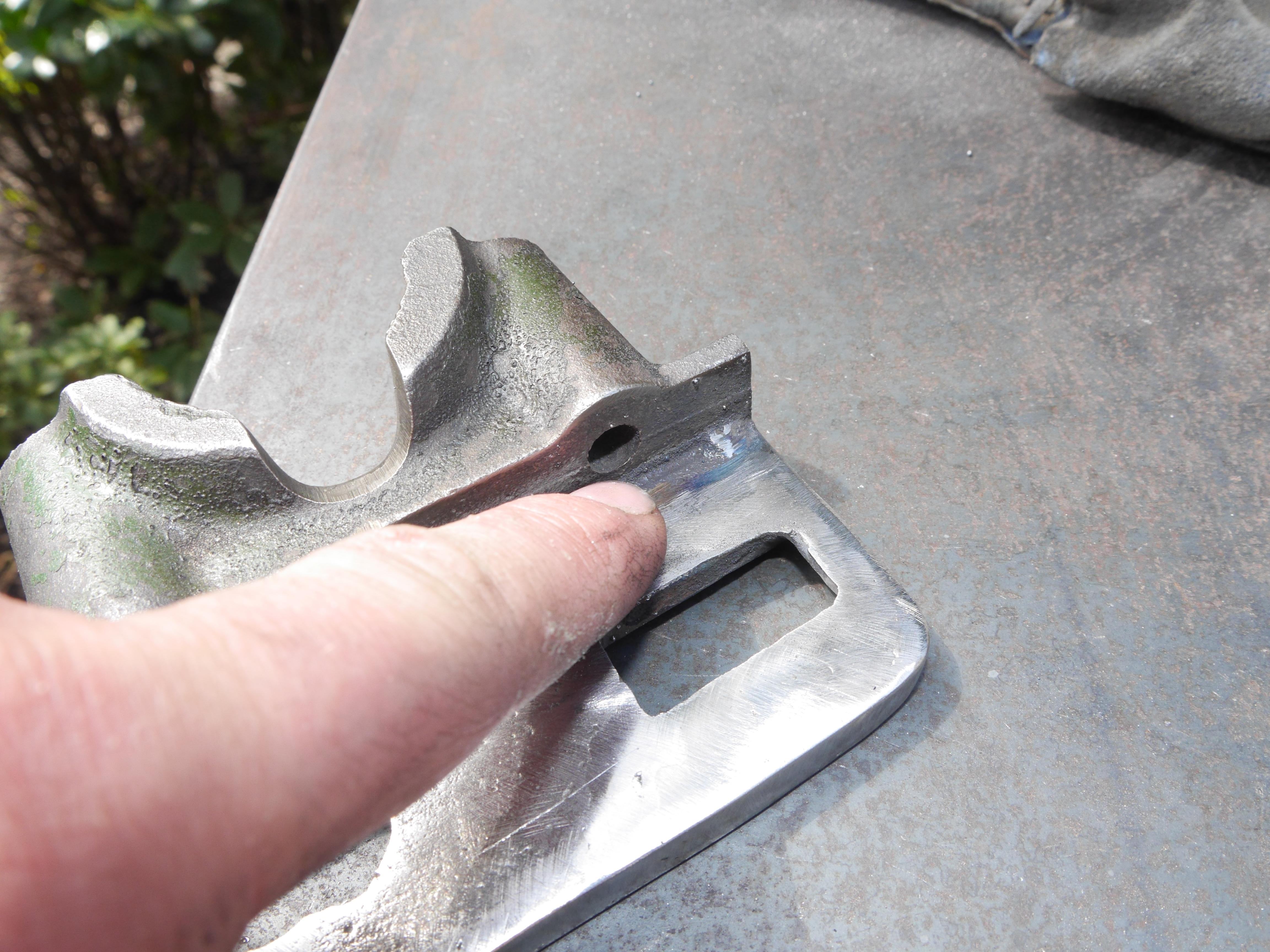
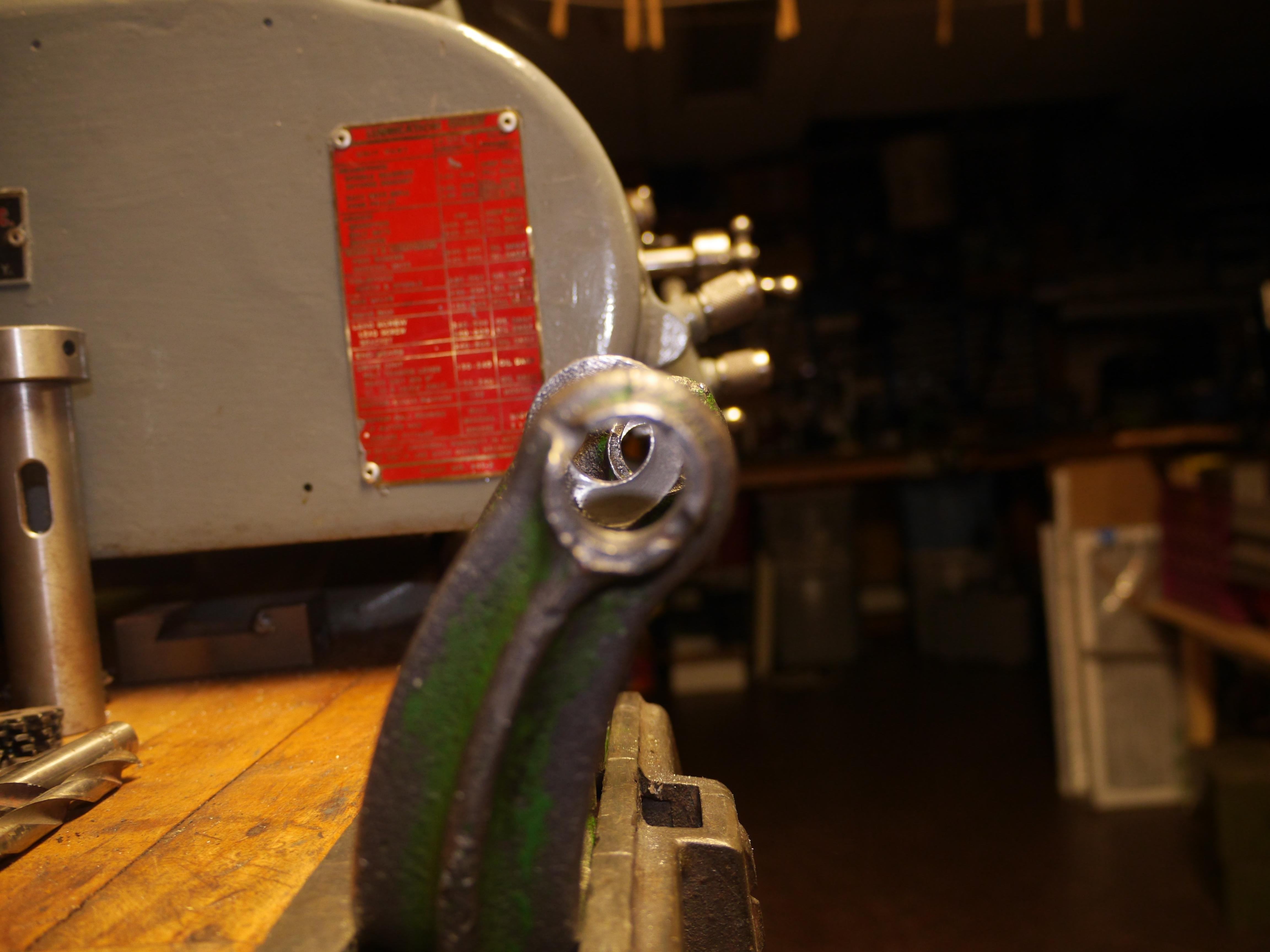
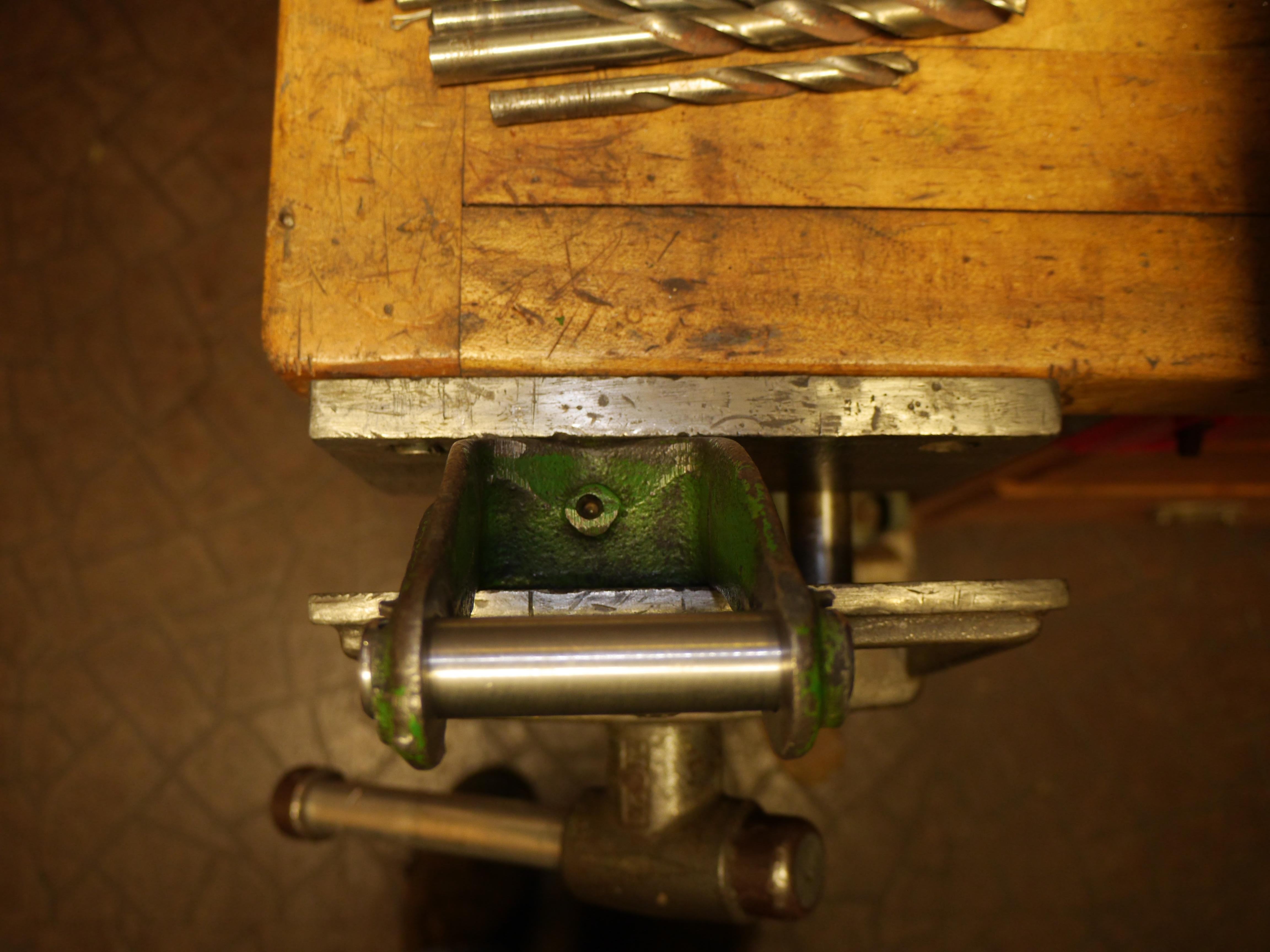
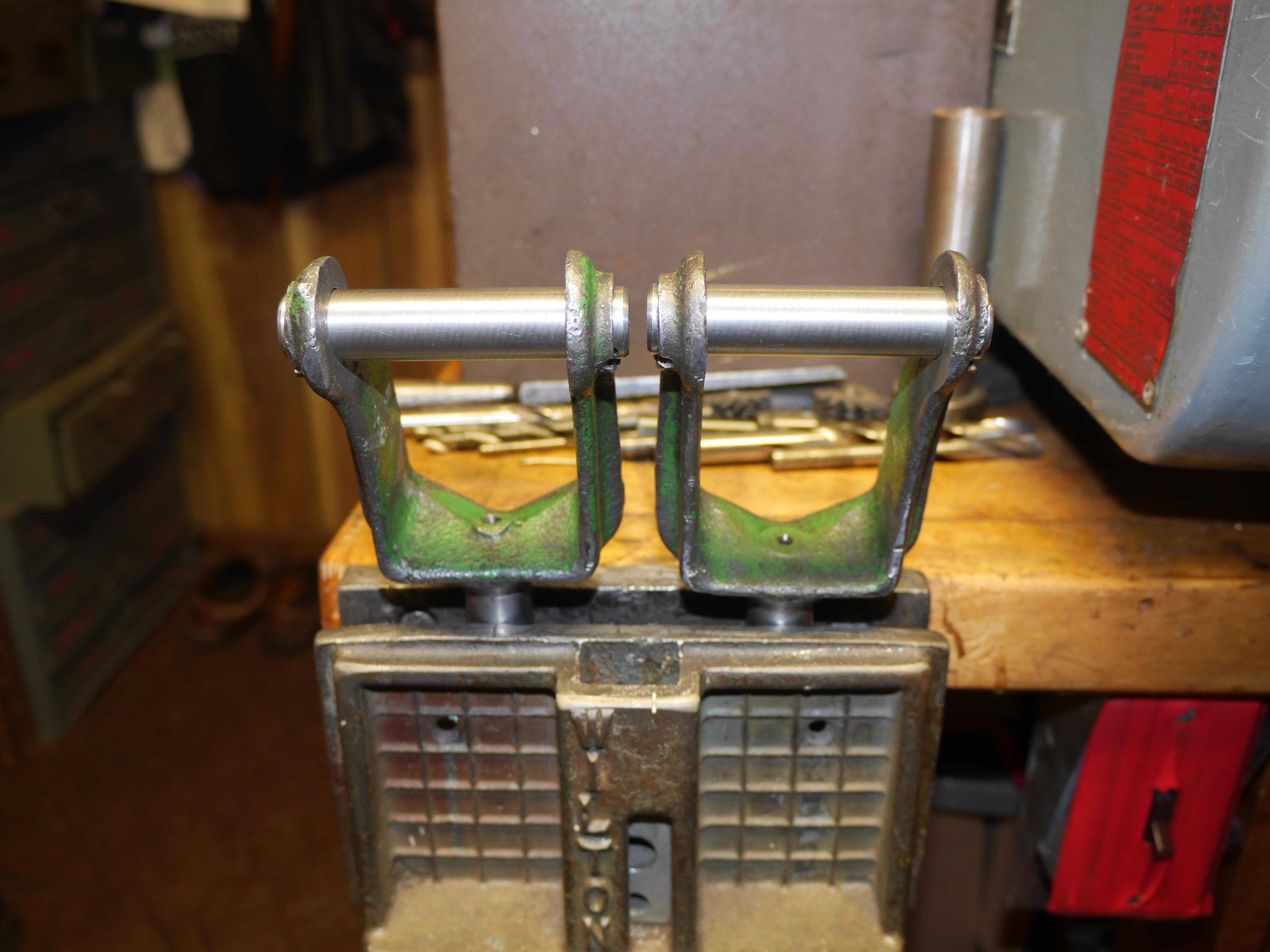
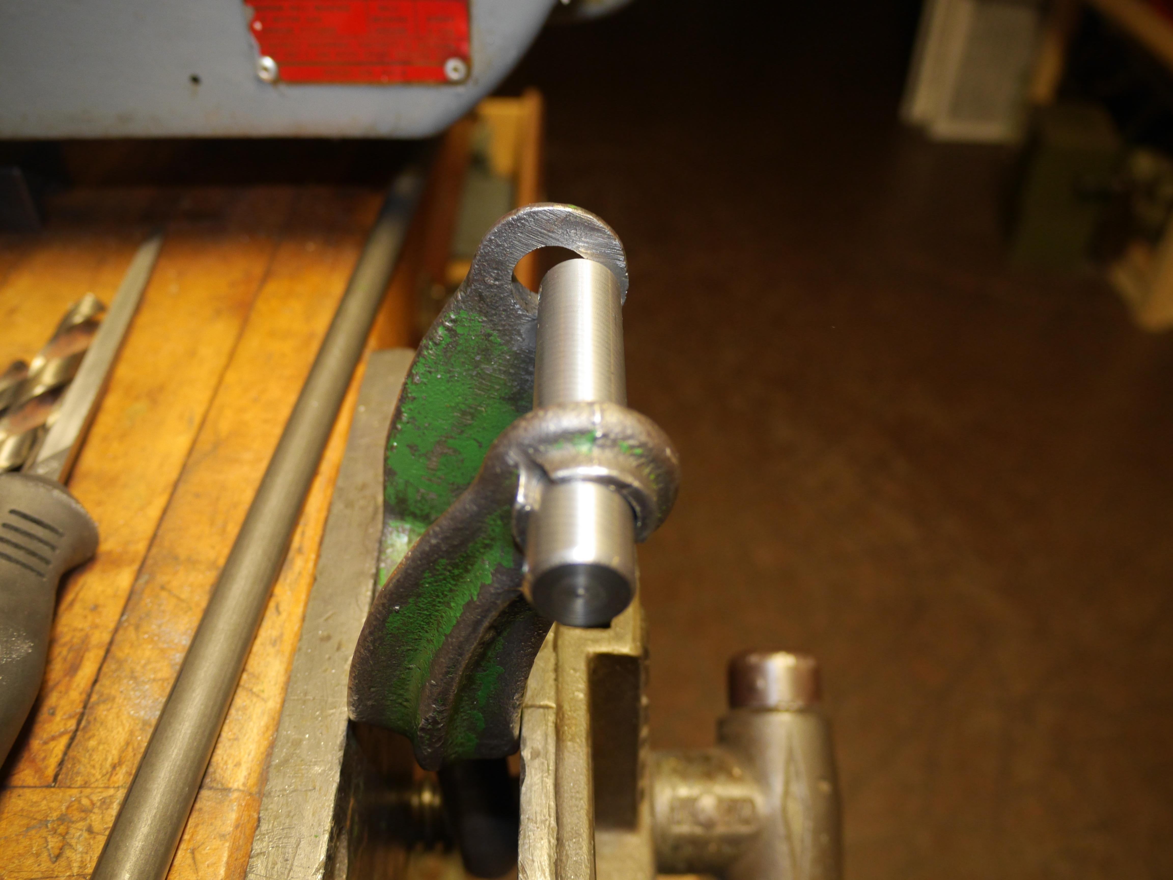
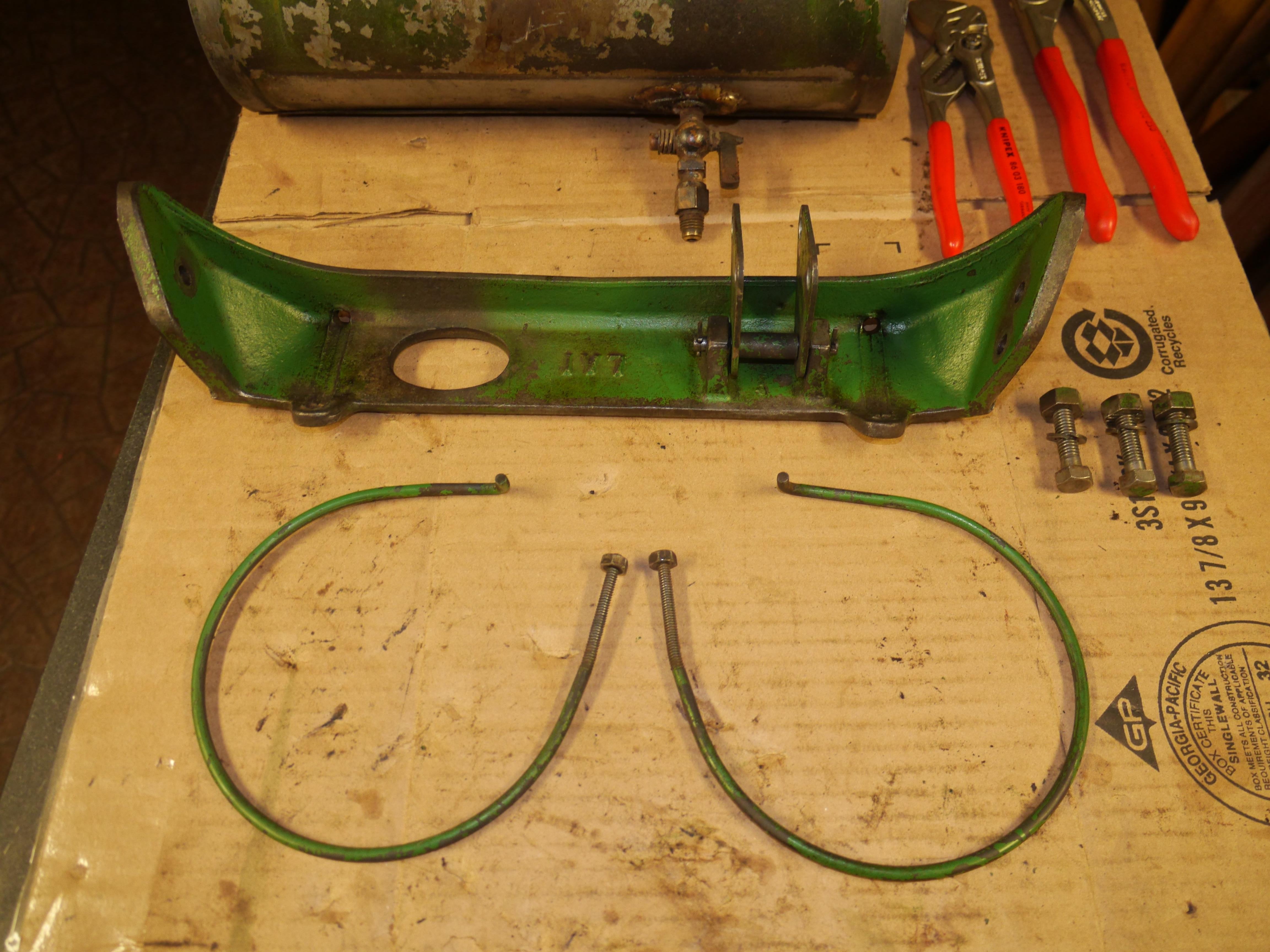
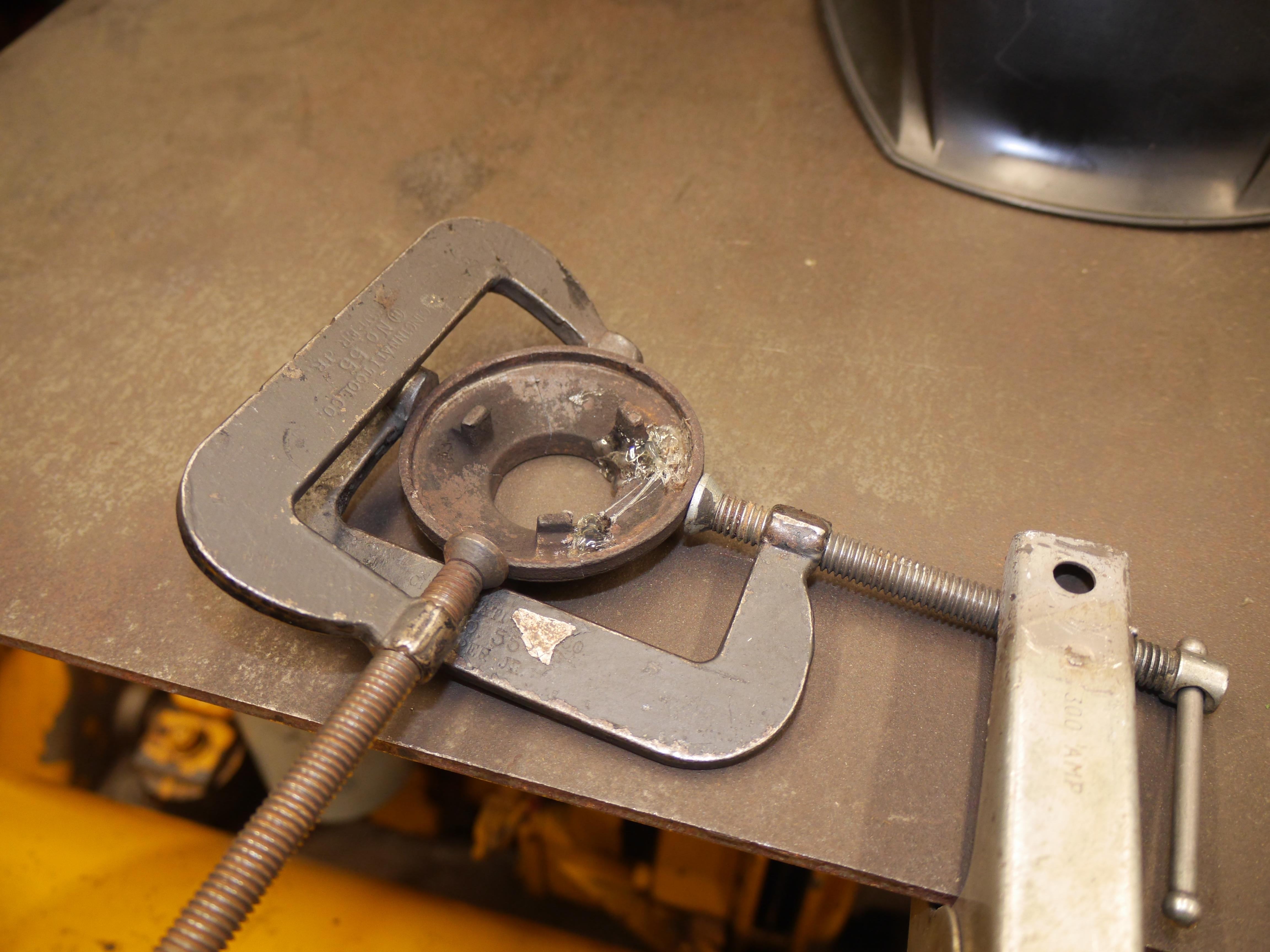
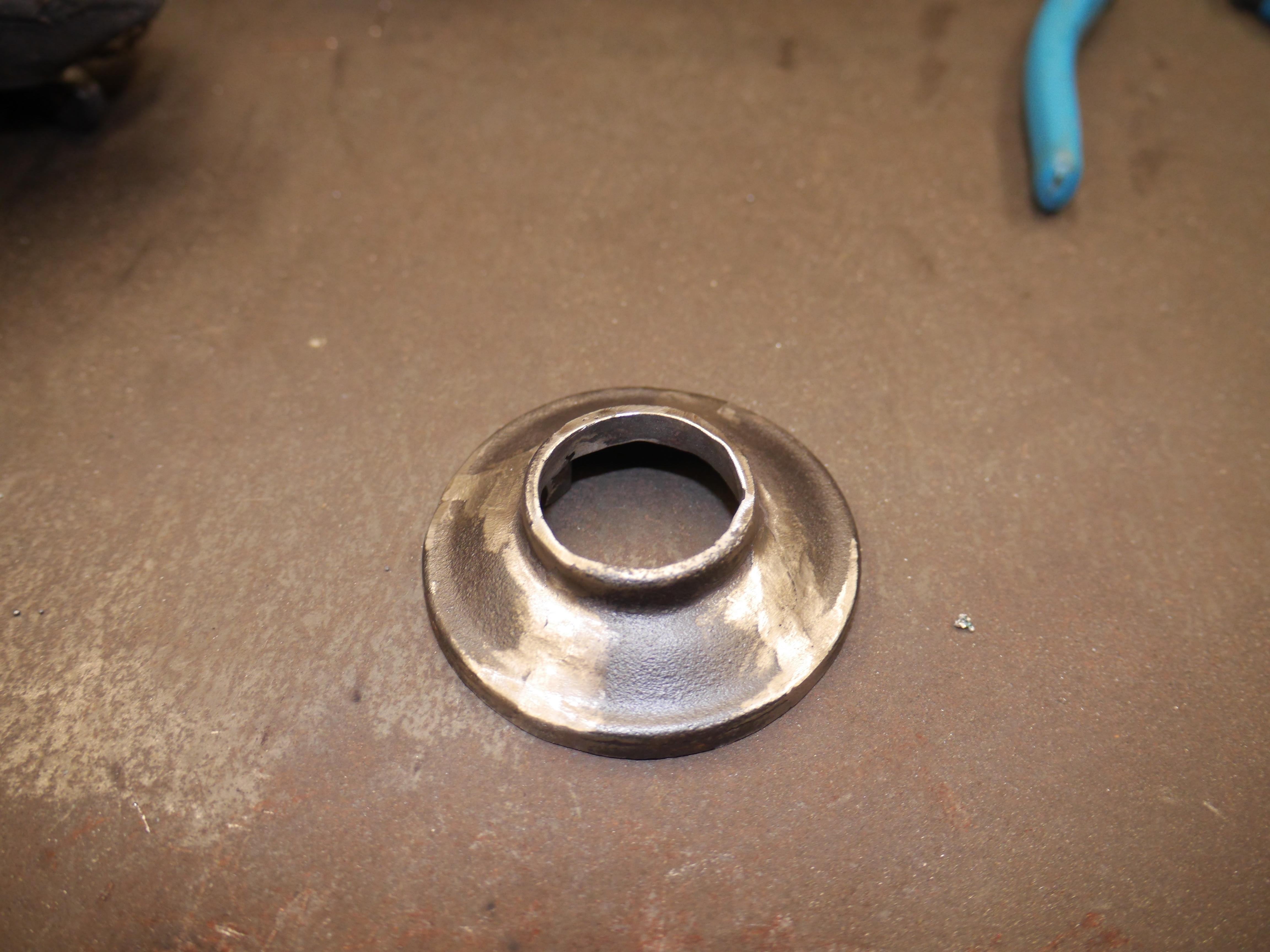
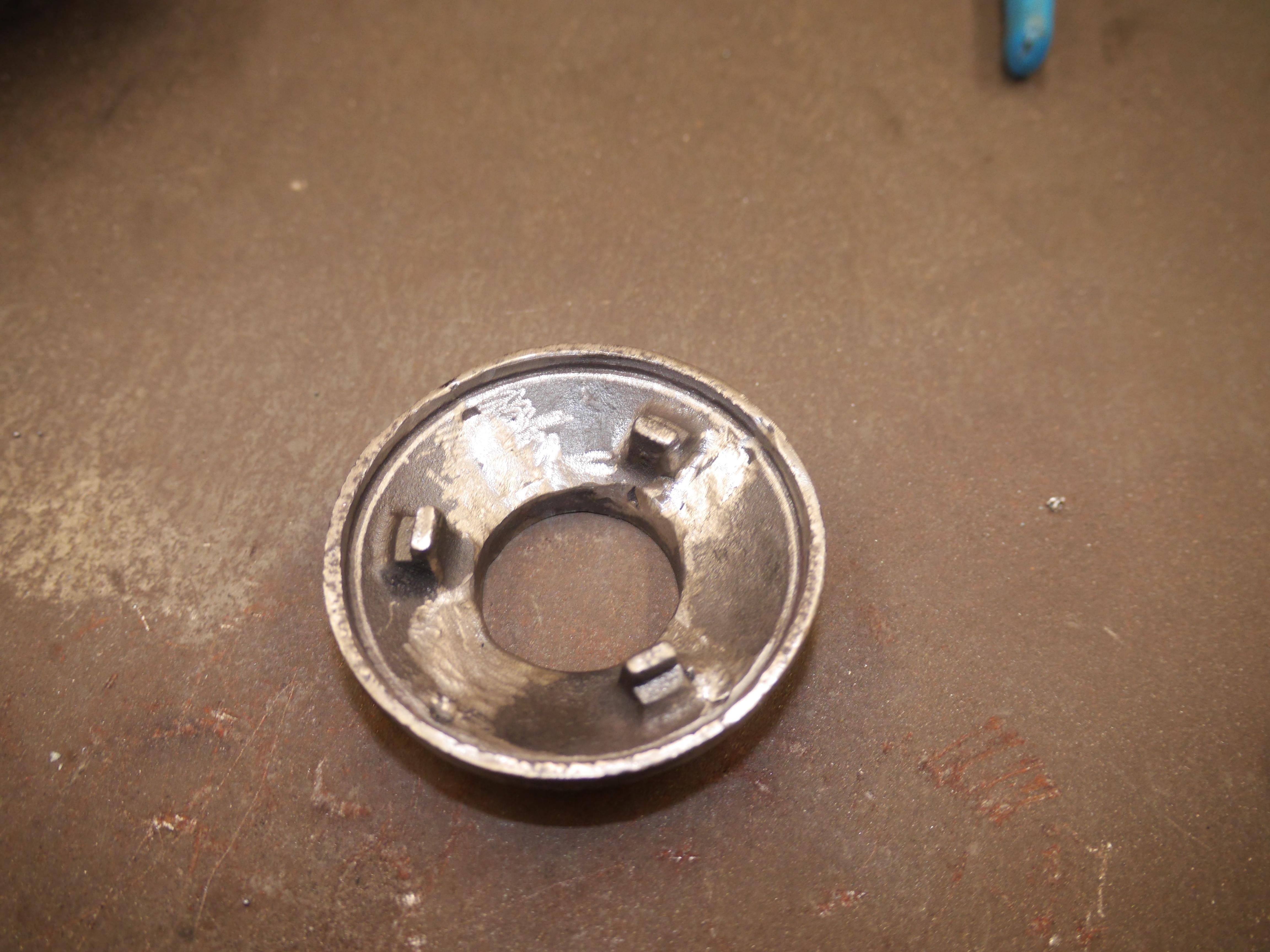
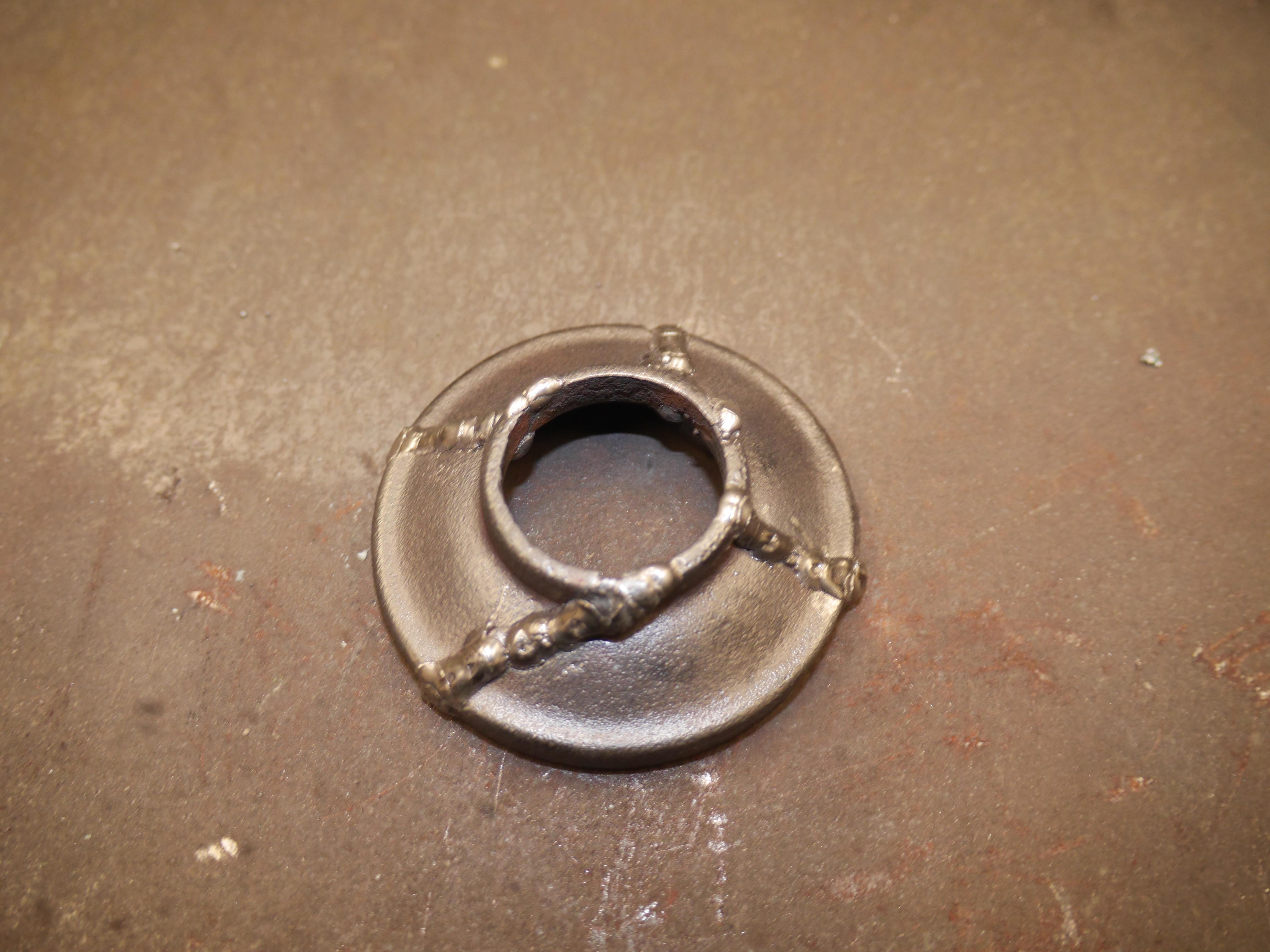
Today I spent some time prepping, pre-heating and welding the damaged axle hanger. The cast iron welded nice preheated to around 700*F. It took a whole lot longer to file the weld down in the tapered contact area than I anticipated. I rubbed the worked area with black and green dye to help add some color to the damaged area. Several more applications will yield a closer match to the original paint that was displaced. With the axle hung back on the mower, I am reaching out to you to see if anyone has a (7/16-14 square head plow bolt) for my mower. I have never seen a fastener quite like this one. The square head is 0.722" and the overall length is 1.293". During the repair procedure I discovered why this casting had broke in the first place. There was a small casting bump left on the rear of the bearing hanger that induced a twist in the casting with both of the bolts snugged down. Years of bouncing around must have caused this part of the housing to fracture and finally break out. Now that the hanger is repaired, it should not break again, at least in my ownership. If anyone has a spare bolt like this, I would be more than willing to pay the shipping on it. There will be an update on the reel end of the mower in the coming days.


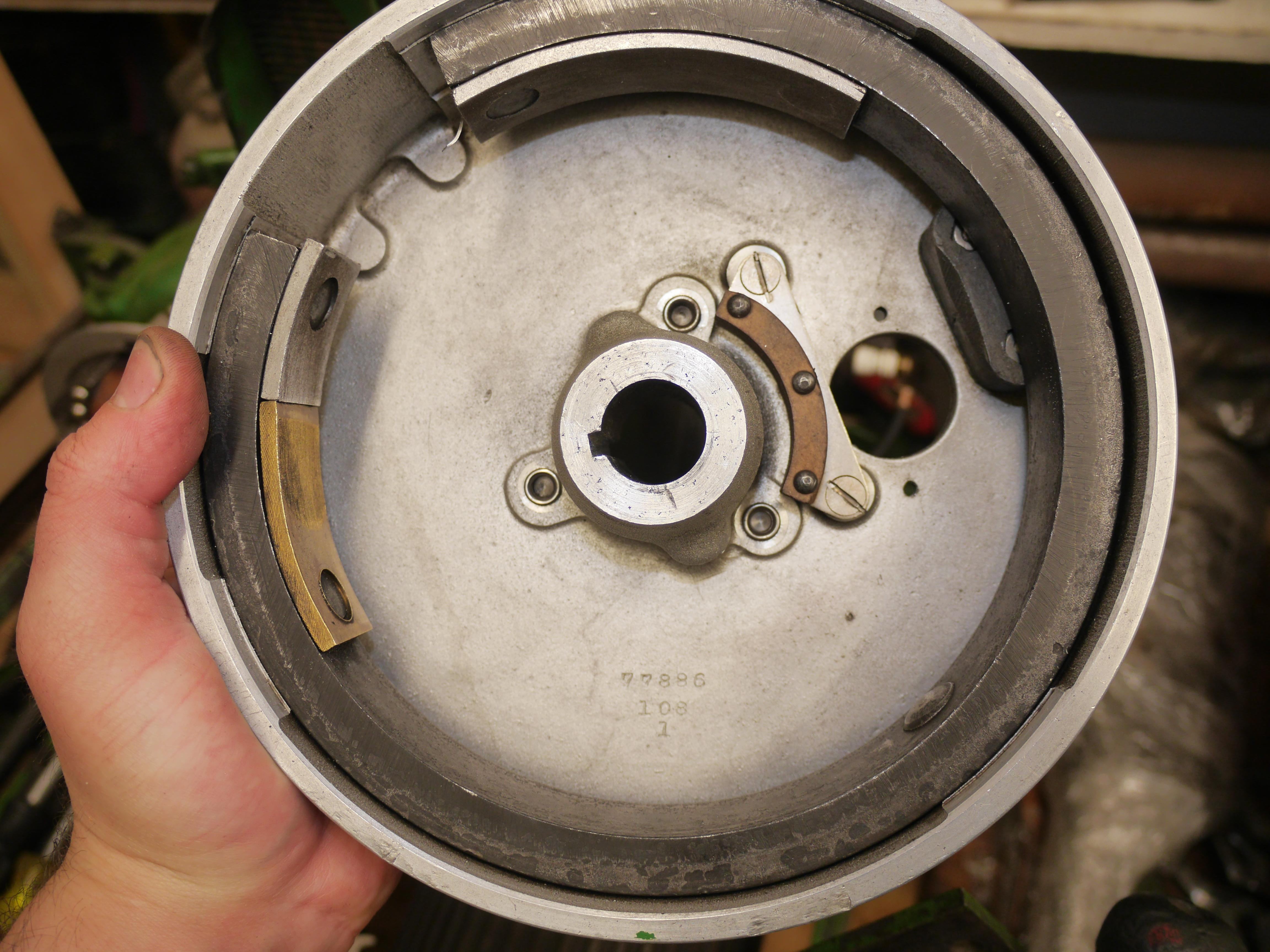
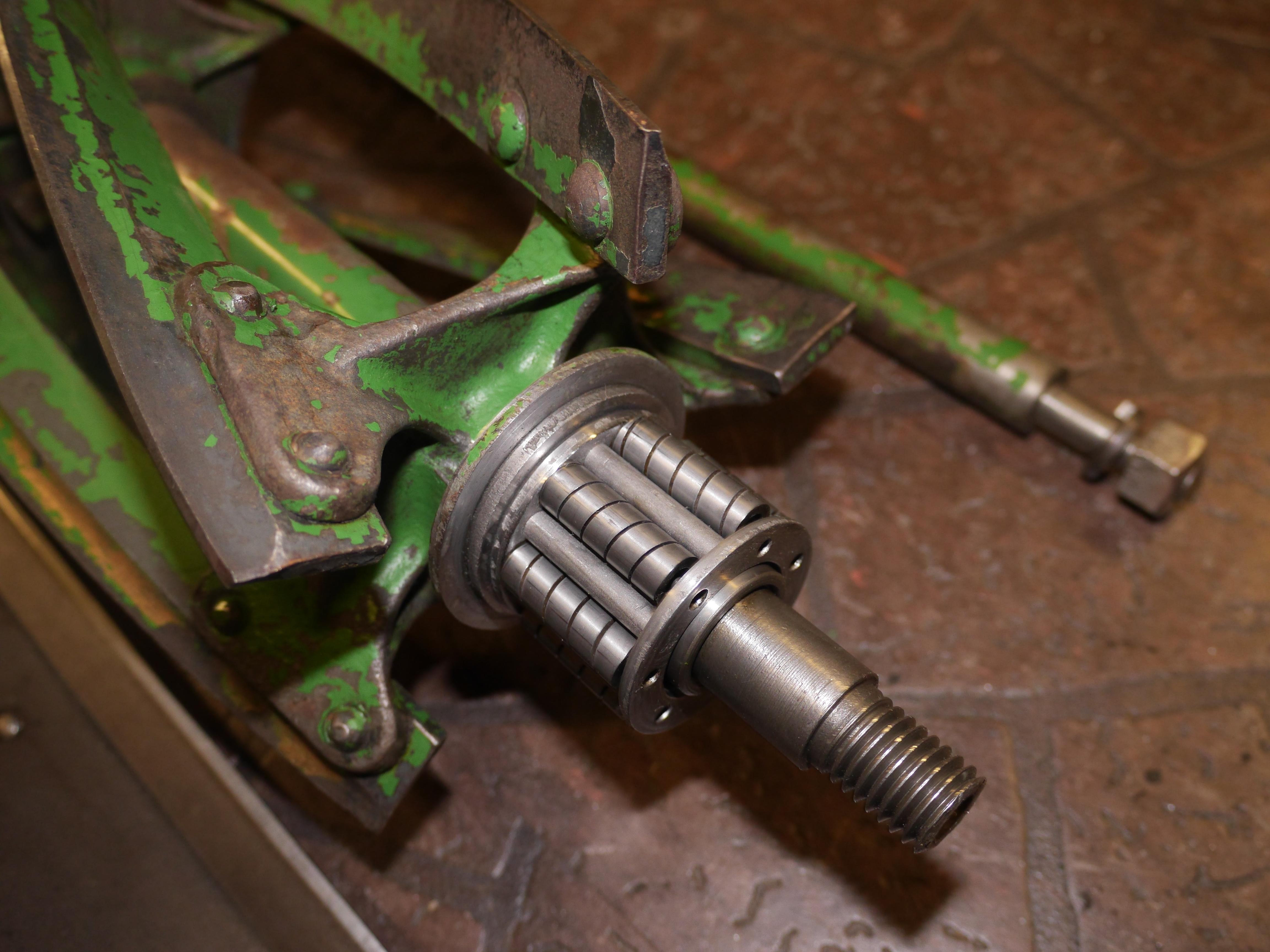
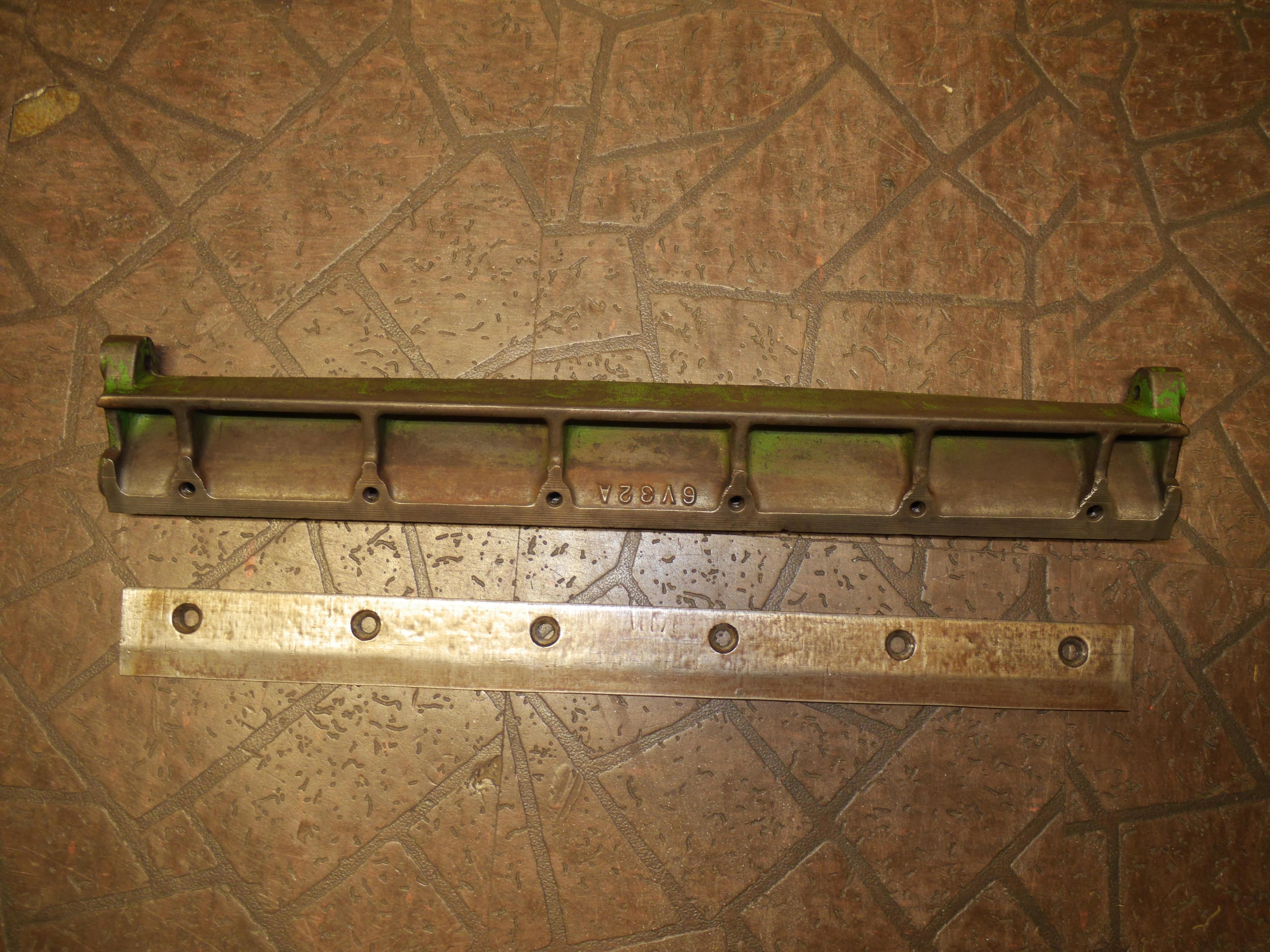
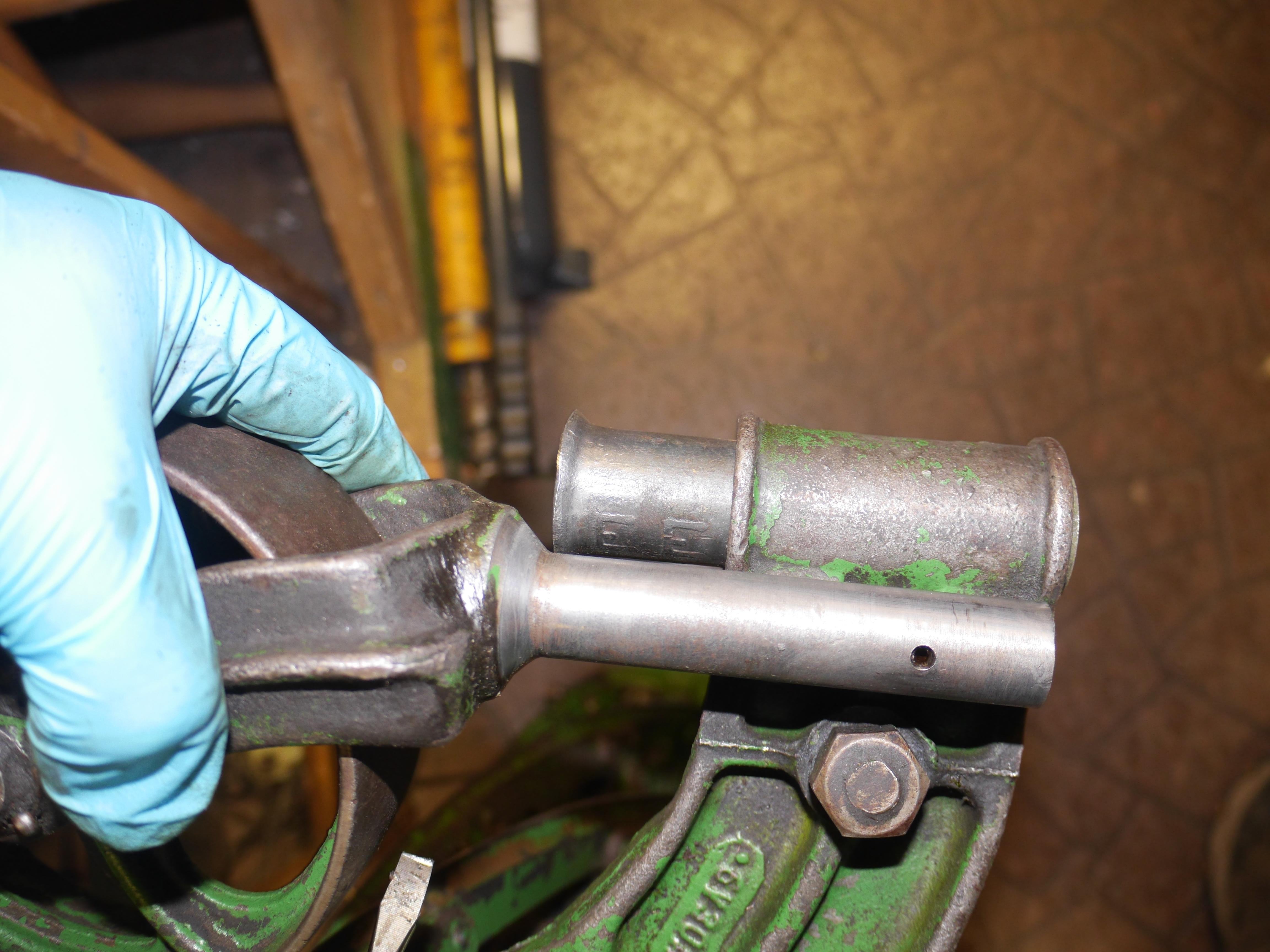
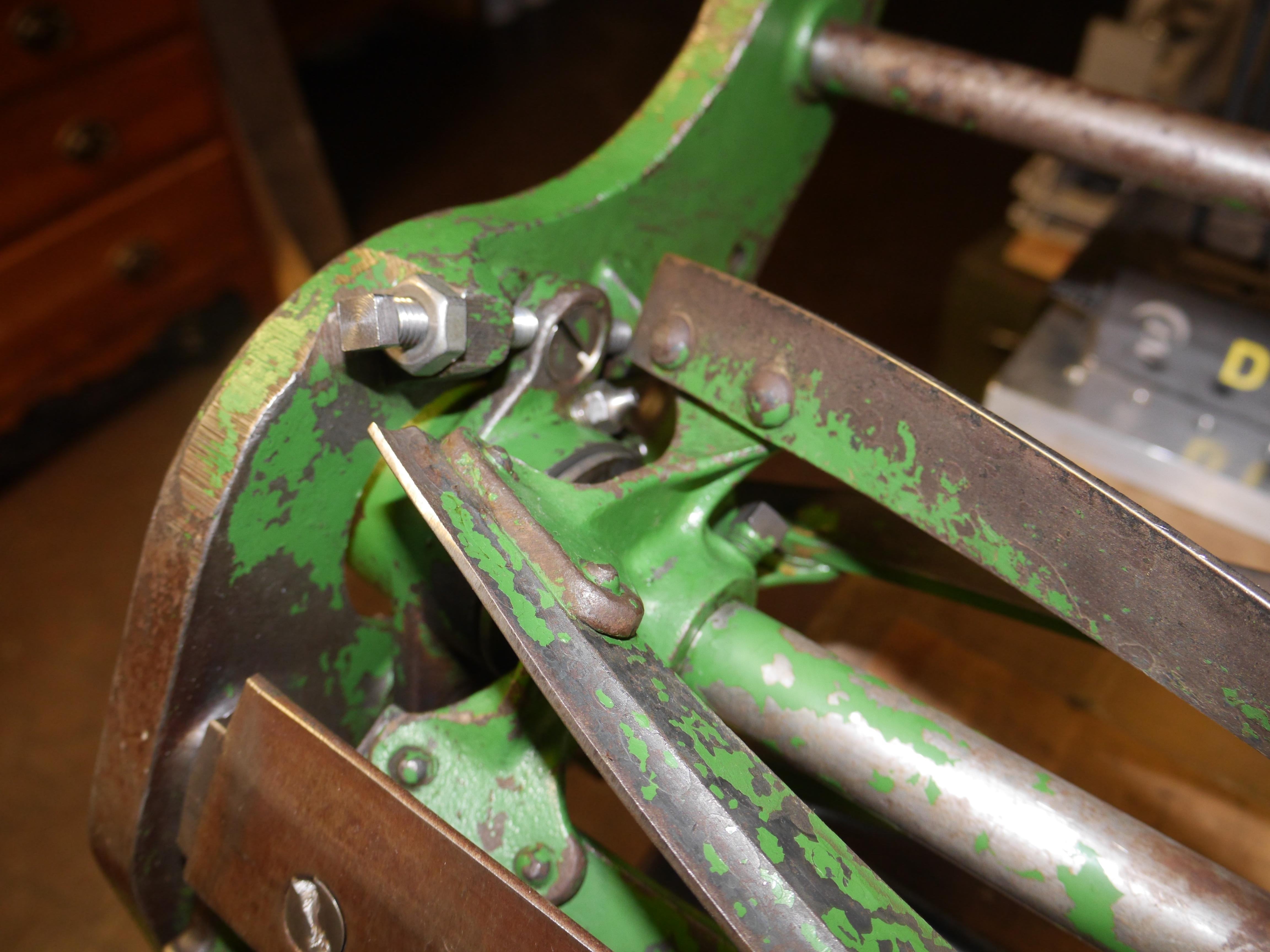
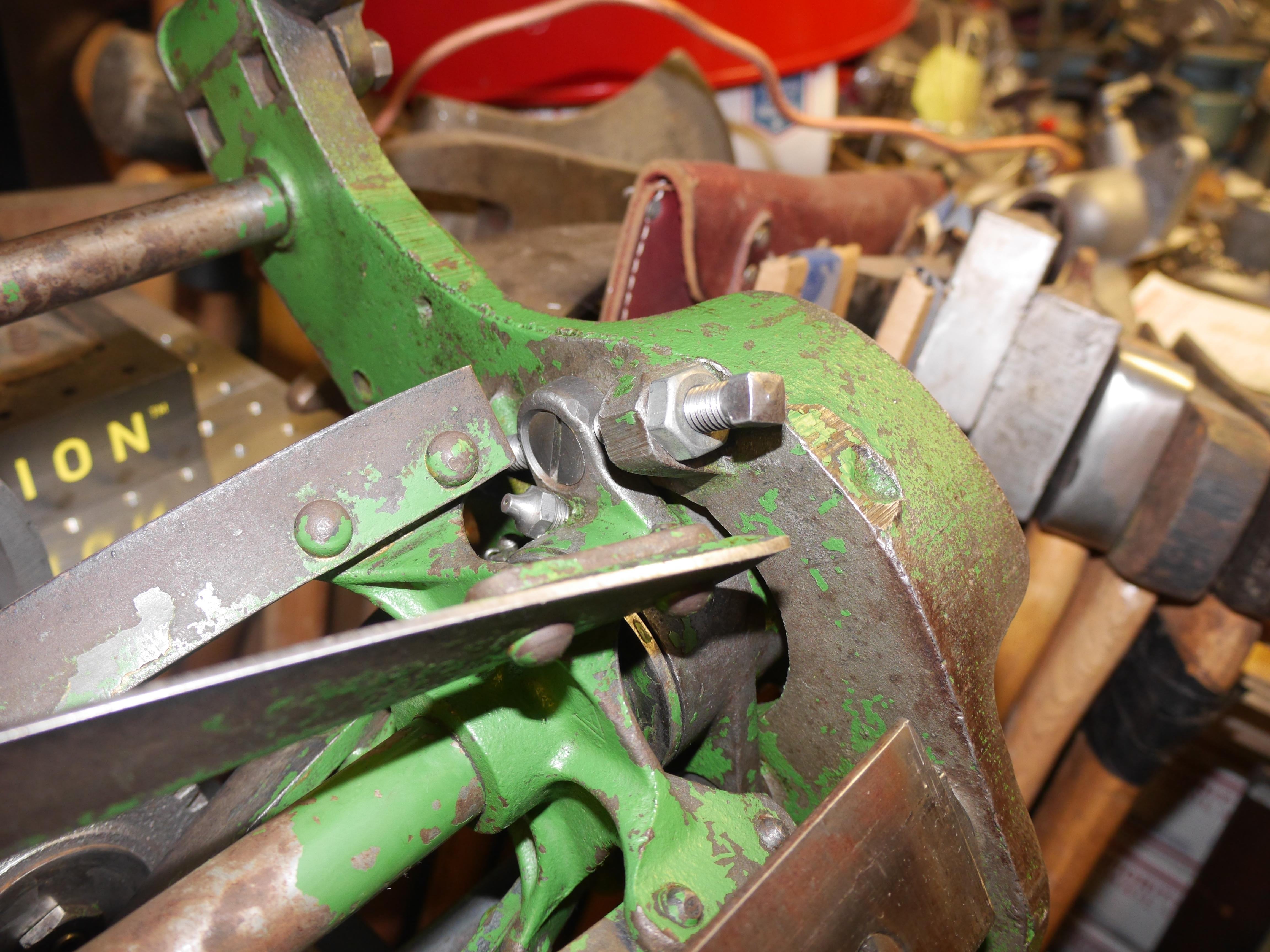
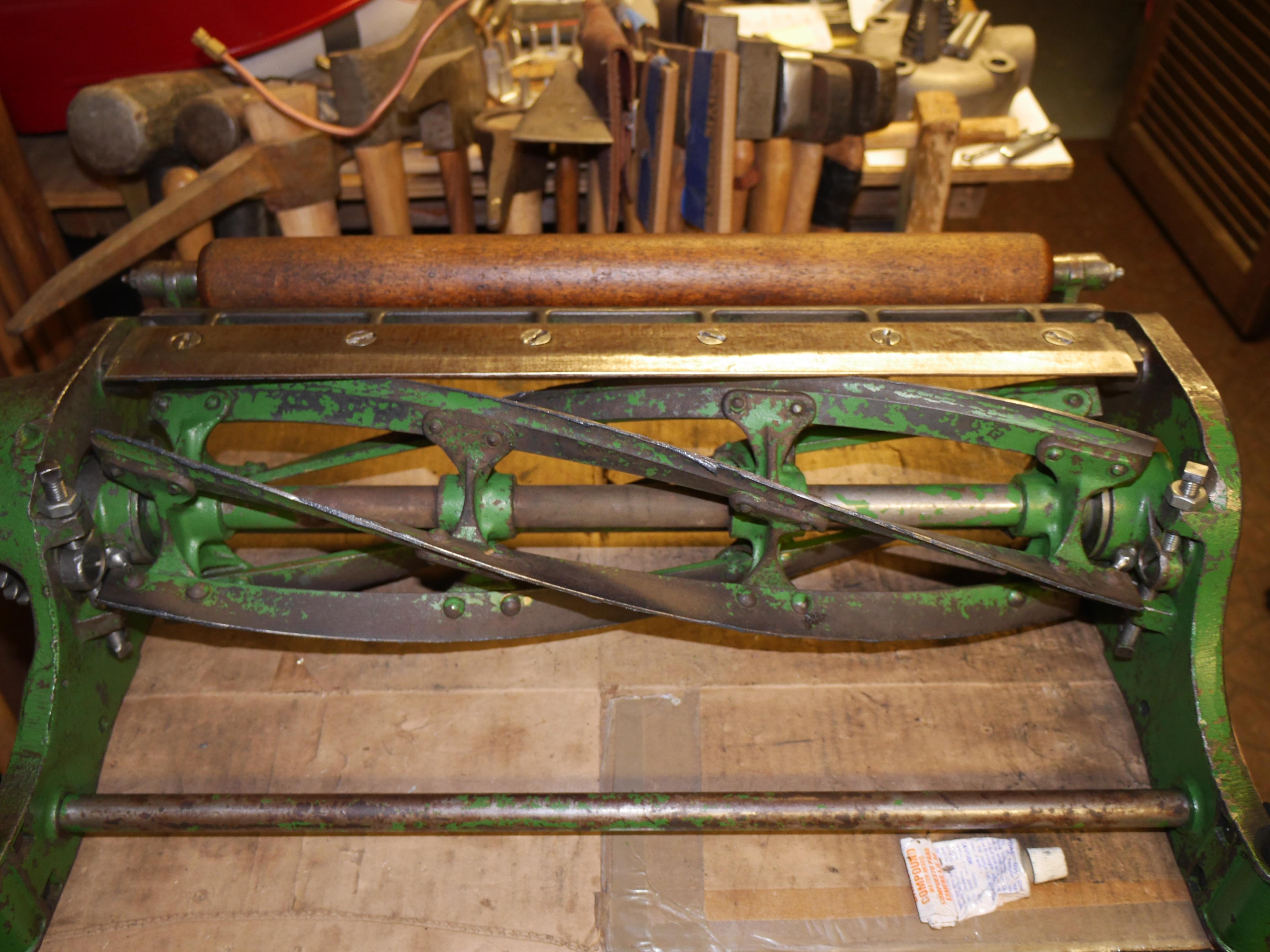
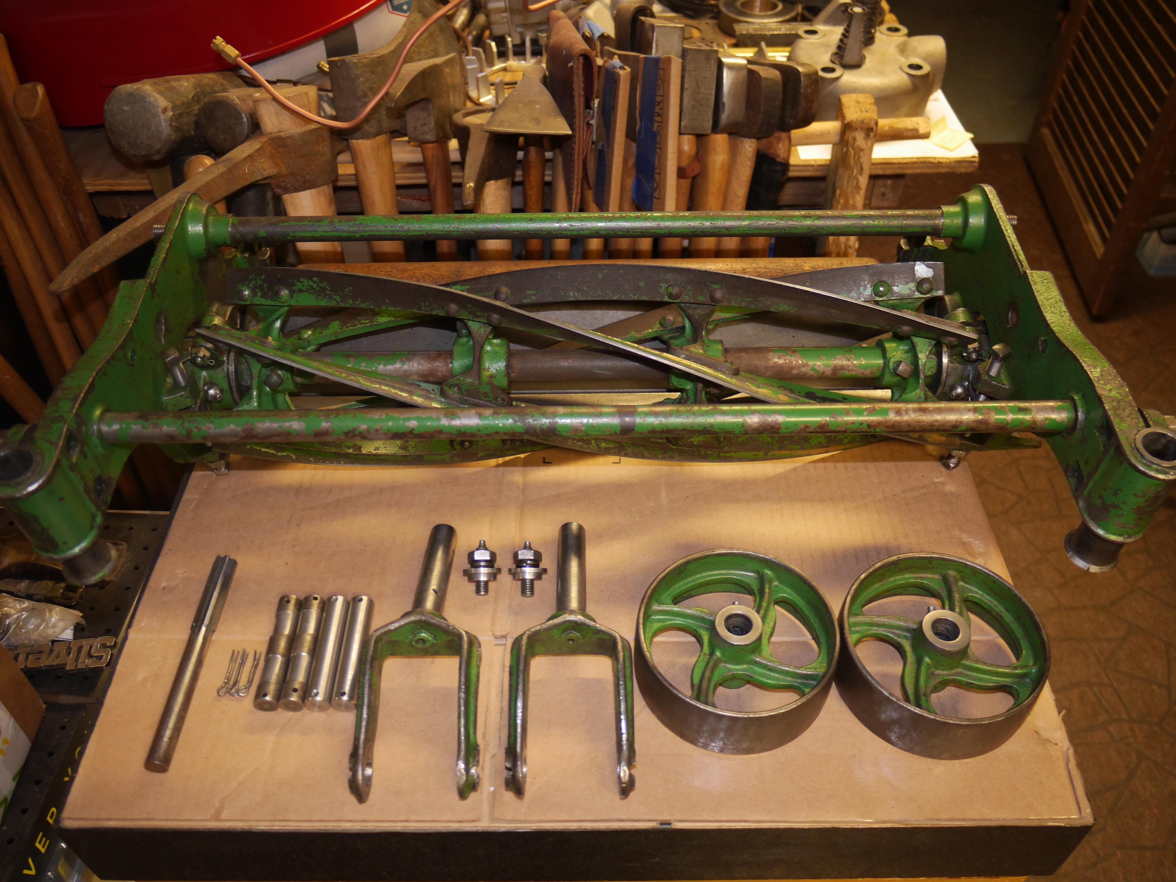
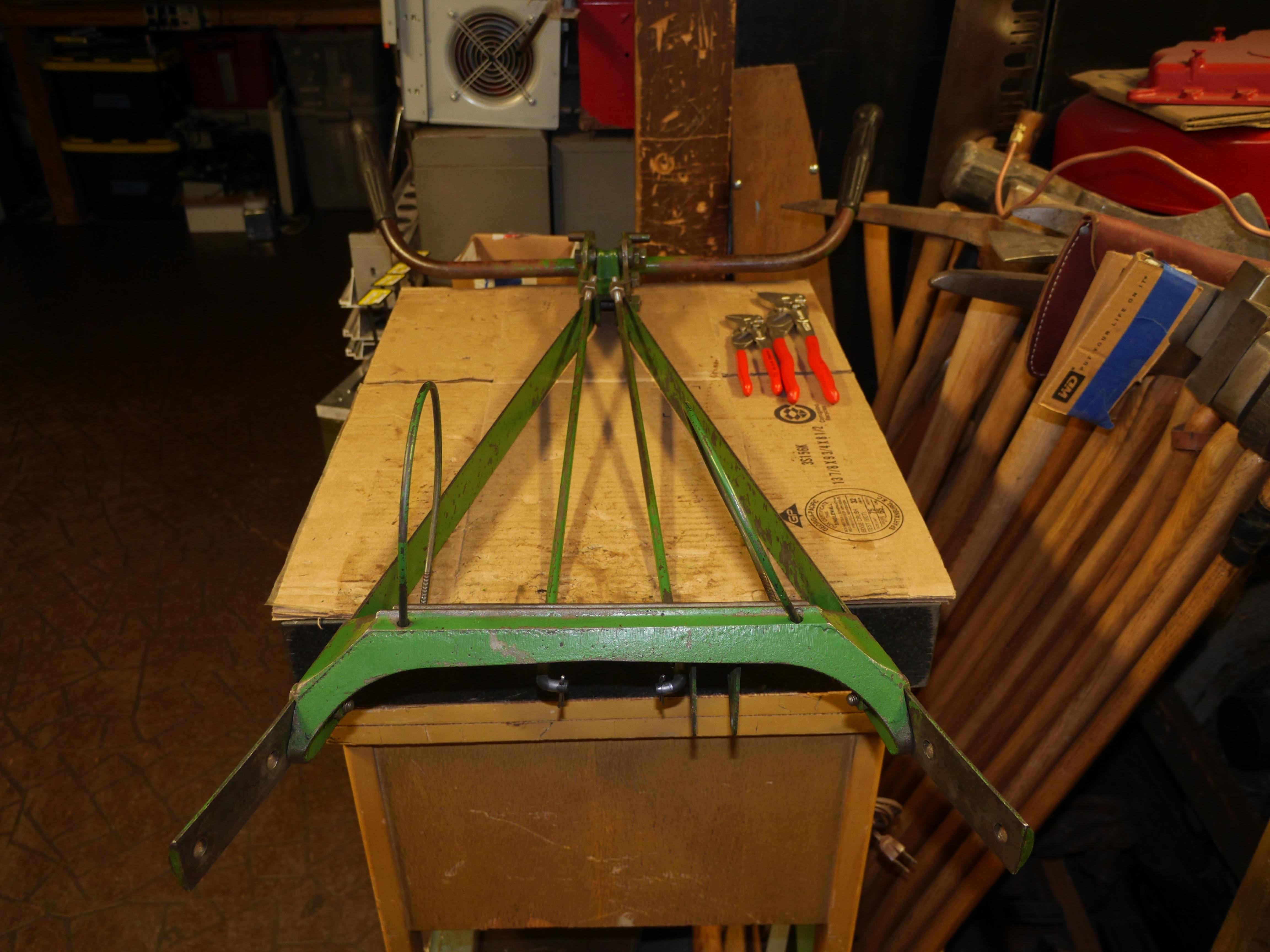
The last few days I have been busy working on the reel end of the 1931 Coldwell. I knew that the spindles were very sloppy so I took the time to carefully disassemble, degrease and meticulously clean every surface of the mower. Disassembly went fairly straight forward, nothing was incredibly tight. I was surprised to see such nice needle bearings for the reel. Before wiping off some of the grease, I thought this mower used similar bearings to a Ford model T. This is the only application I have ever seen a needle bearing with inverted flutes in every roller to help pump and hold grease. The copper jacketed babbitt bearings in either of the cast iron guides were in just perfect condition. What is even more incredible is that there was not a lick of rust anywhere on the reel, bed knife or lower cast iron bed knife support. The bed knife appears to be tool steel, which is just wonderful, a sign of a quality mower. As I continued to clean the reel I discovered quite a bit of original gold leafing on the back side of the reel knives, and on the edges of the knives. With all of the great aspects of this mower aside, there are a number of worn components which I will cover in subsequent posts.

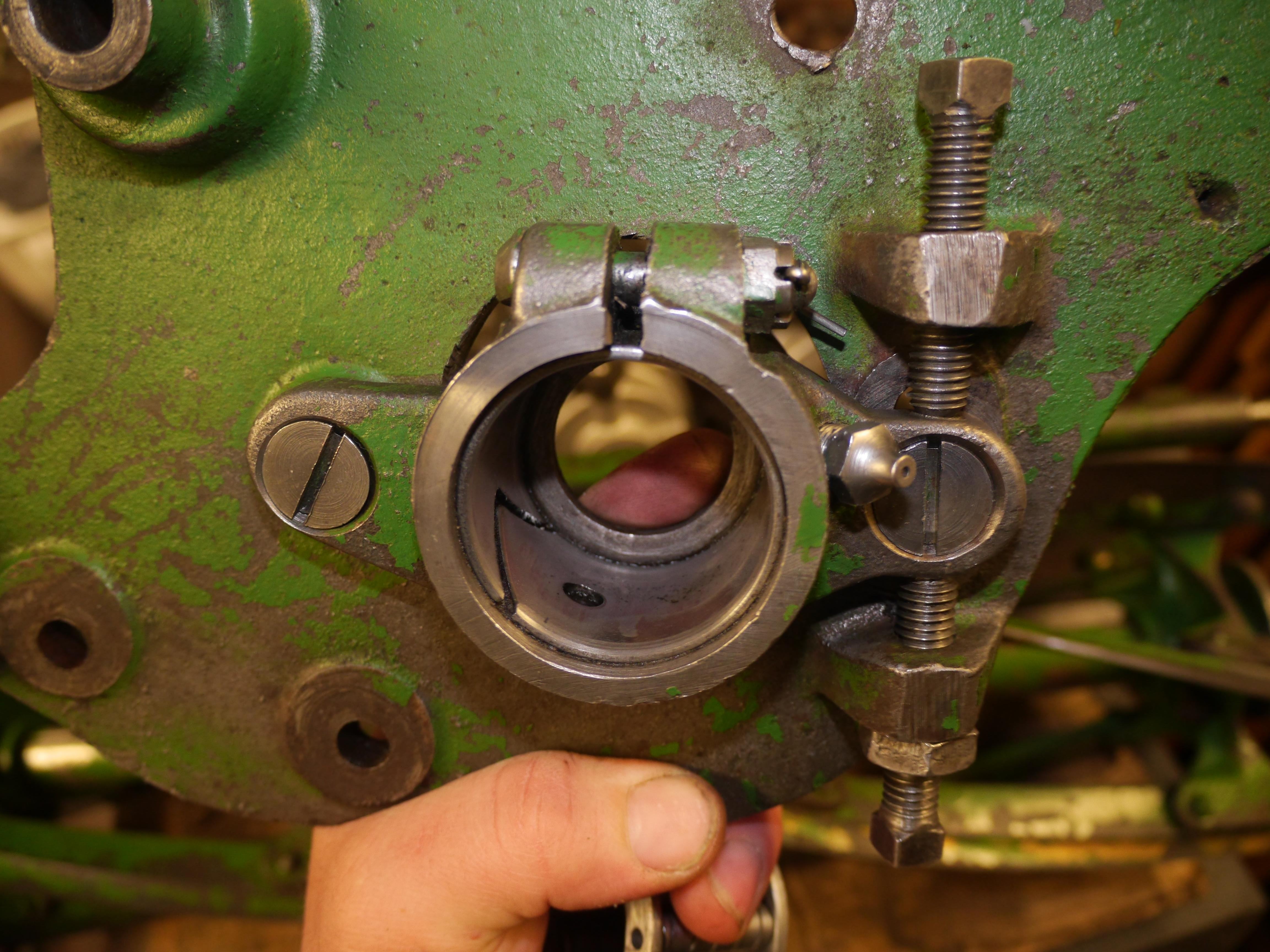
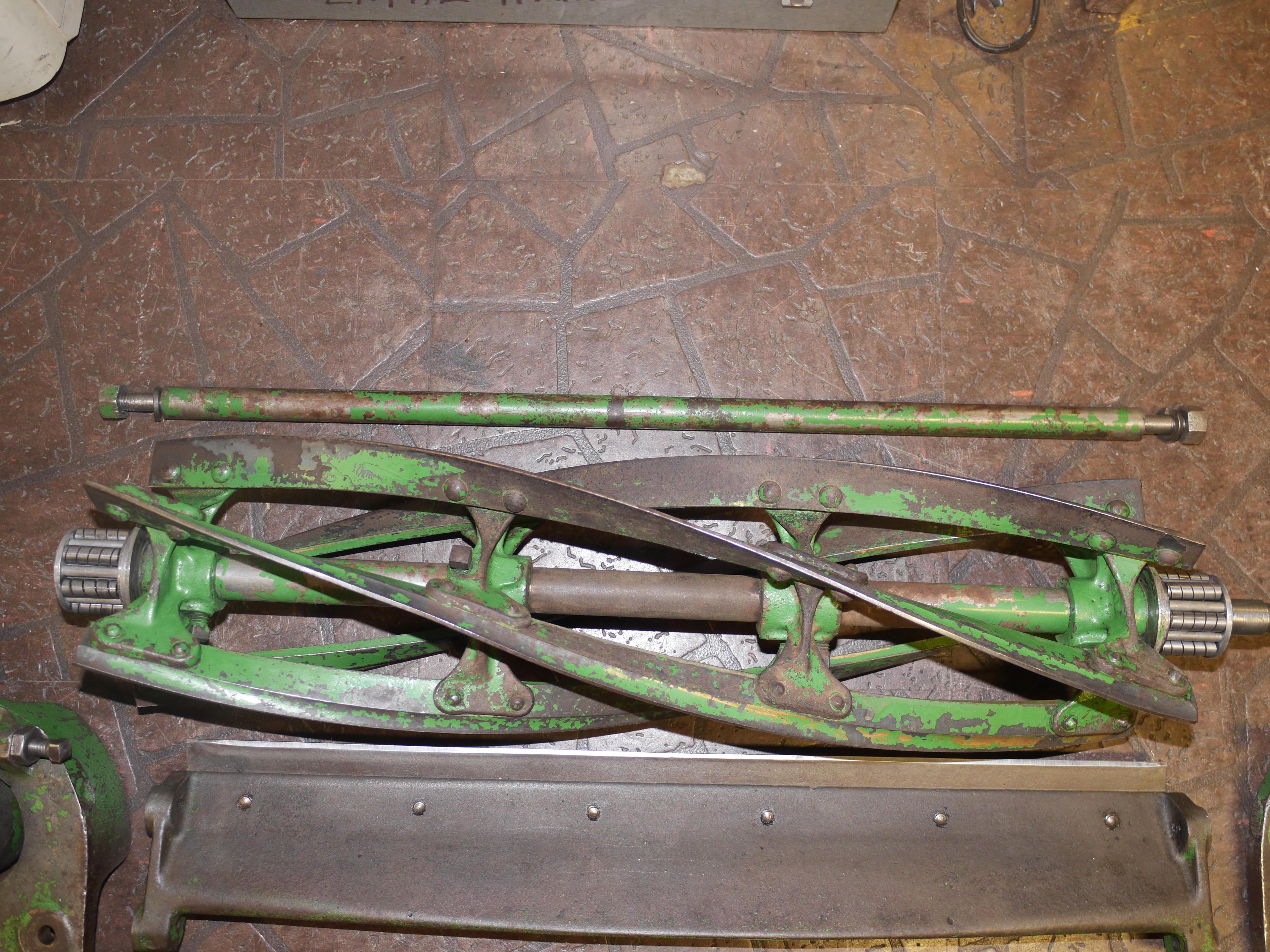
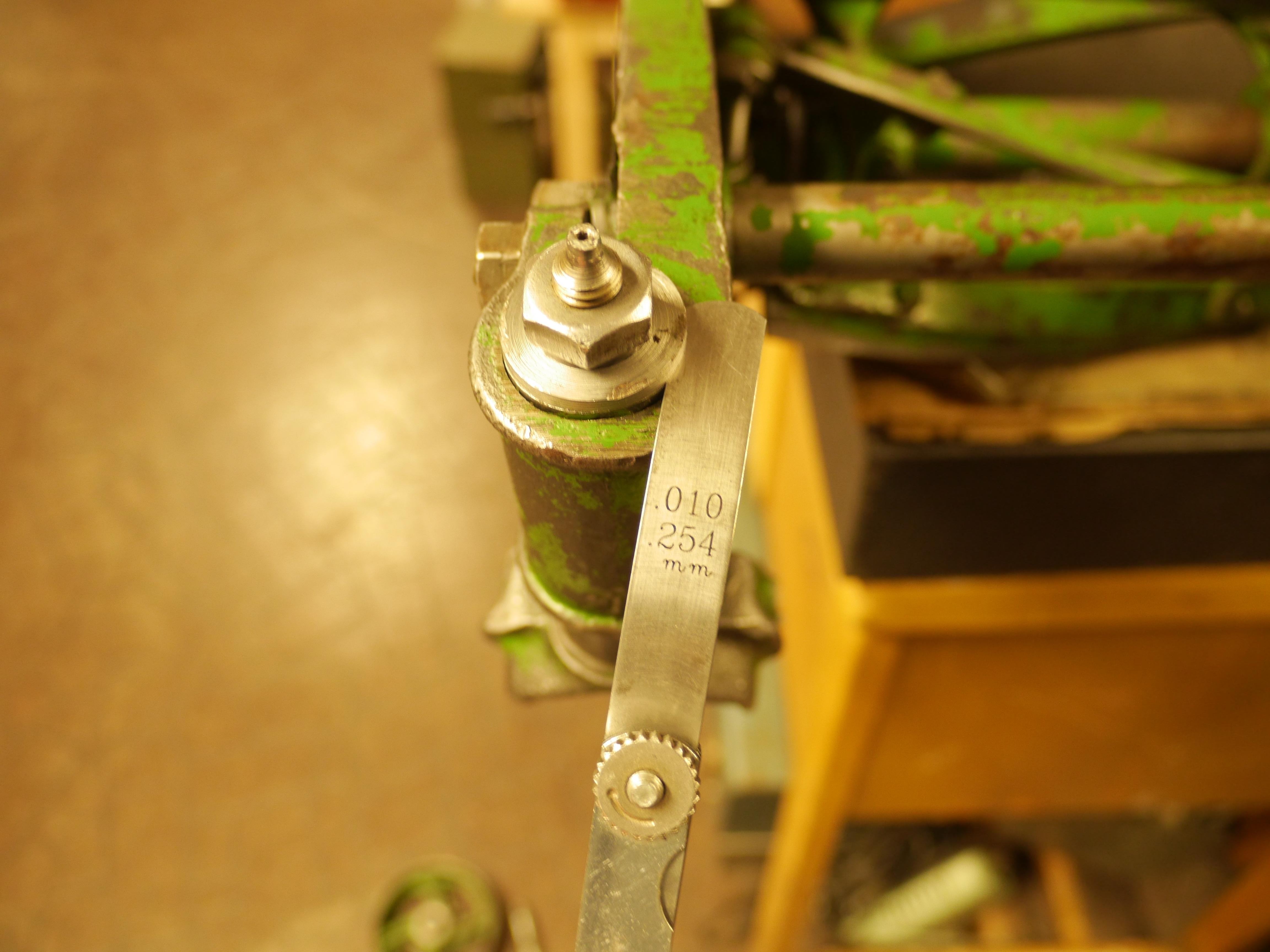
I knew that the spindles were very sloppy, so I had planned for the worst and was ready to weld/turn the spindles back to size, but that was not necessary. It turns out that the female receiver of the spindle is nothing more than a piece of black iron pipe expanded on one end to create a tapered sealing surface. The grease cavity was so packed with hard dried up grease that the spindles could not be properly torqued down. I was measuring anywhere from 0.065" to 0.085" of vertical movement in each spindle. With a tapered seat, that translated to nearly a quarter inch of angular movement. To my surprise the spindles showed virtually no wear. After cleaning out all of the hard grease, I test fit the spindles dry and the vertical clearance in each spindle was cut down to roughly 0.040". I saw that there was room to improve this, so I machined the stepped collar on the top of the female receiver down to achieve the 0.010" vertical clearance I was looking for. This 0.010" measurement is arbitrary, I personally felt that this amount of clearance would allow for a good film of grease to build, yet operate smoothly without binding up. With 0.010" of vertical clearance, the angular movement of the spindle is virtually nothing as the taper of the spindle is always in contact with the tapered seat.

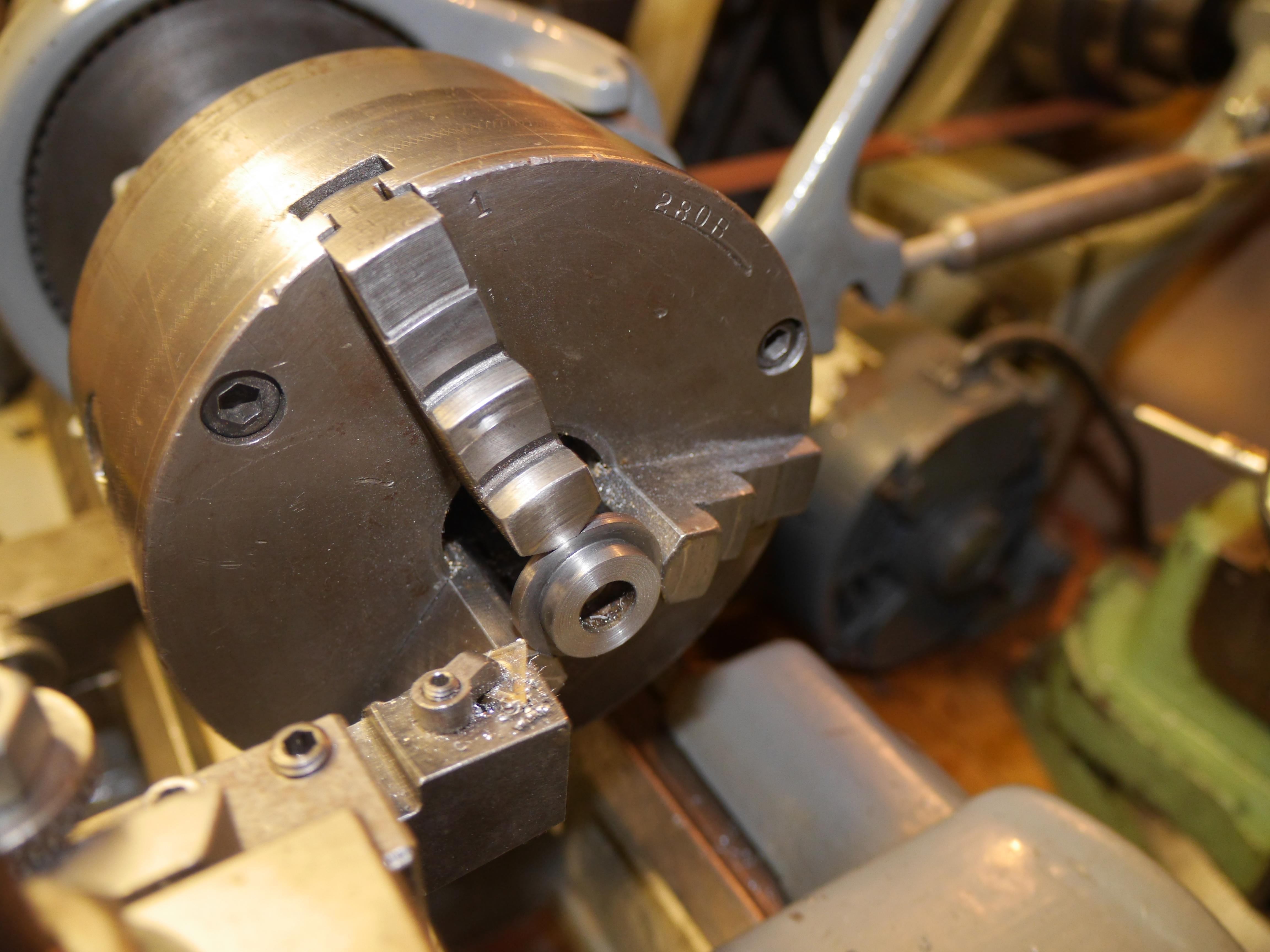
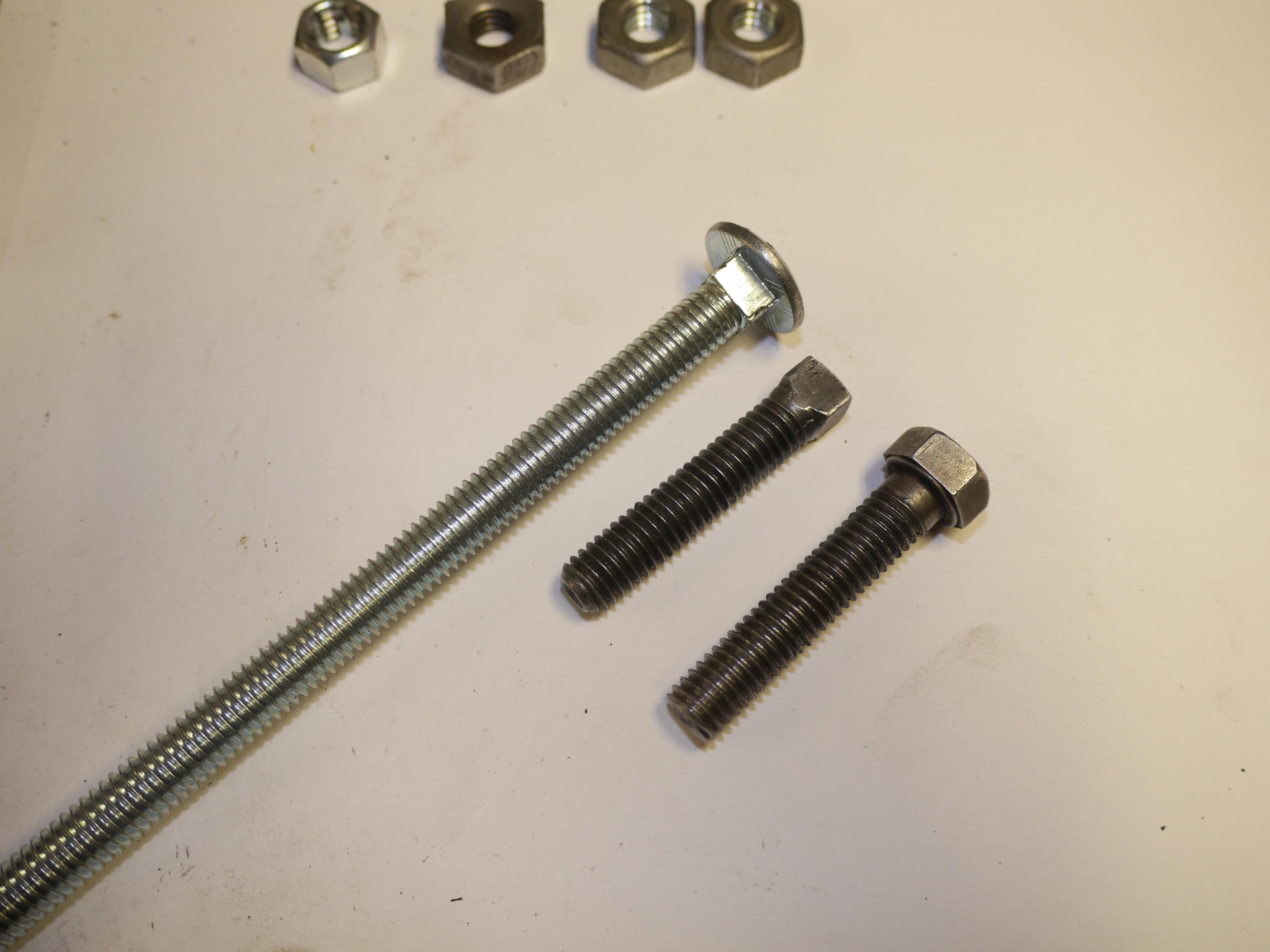
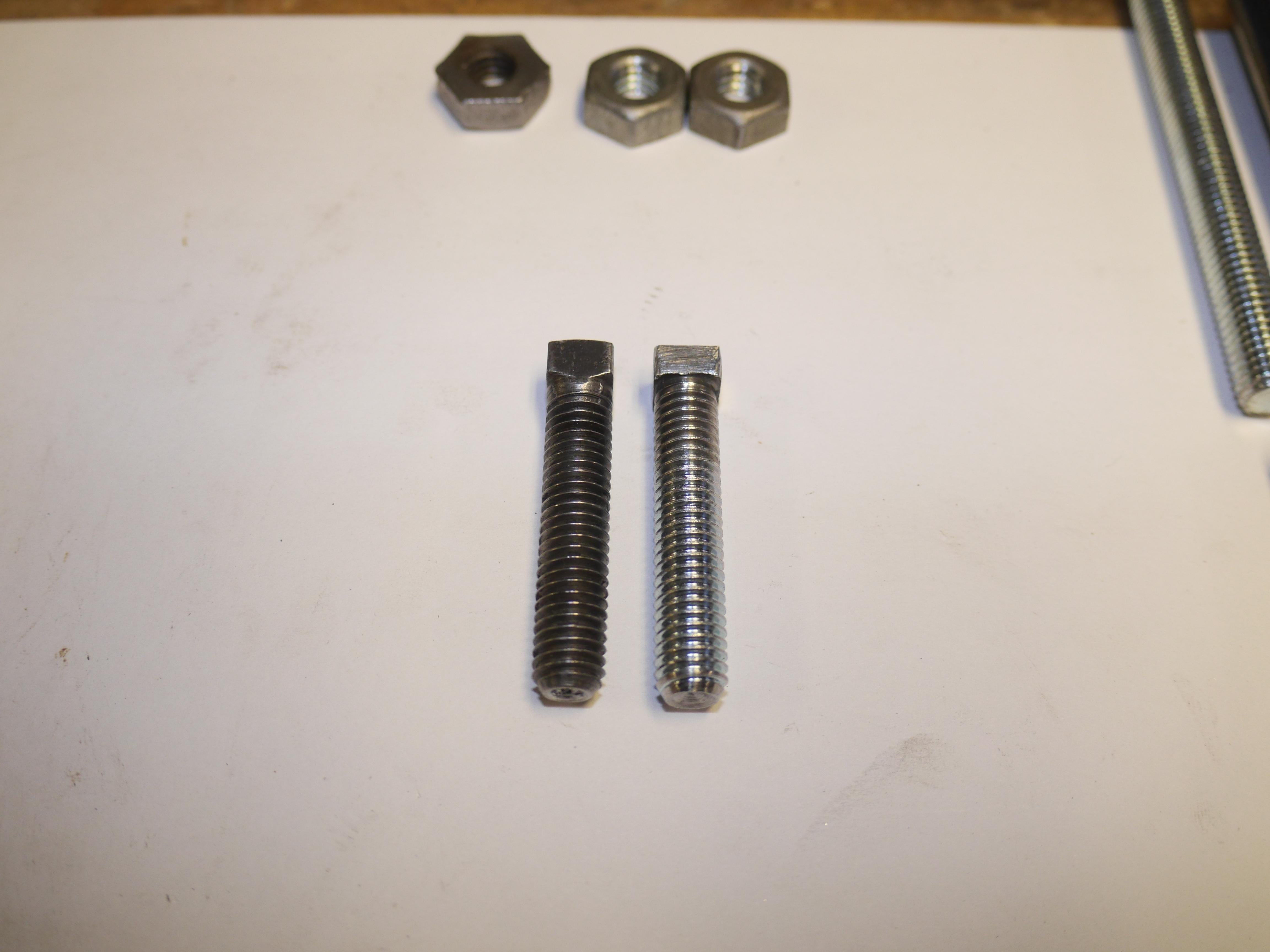
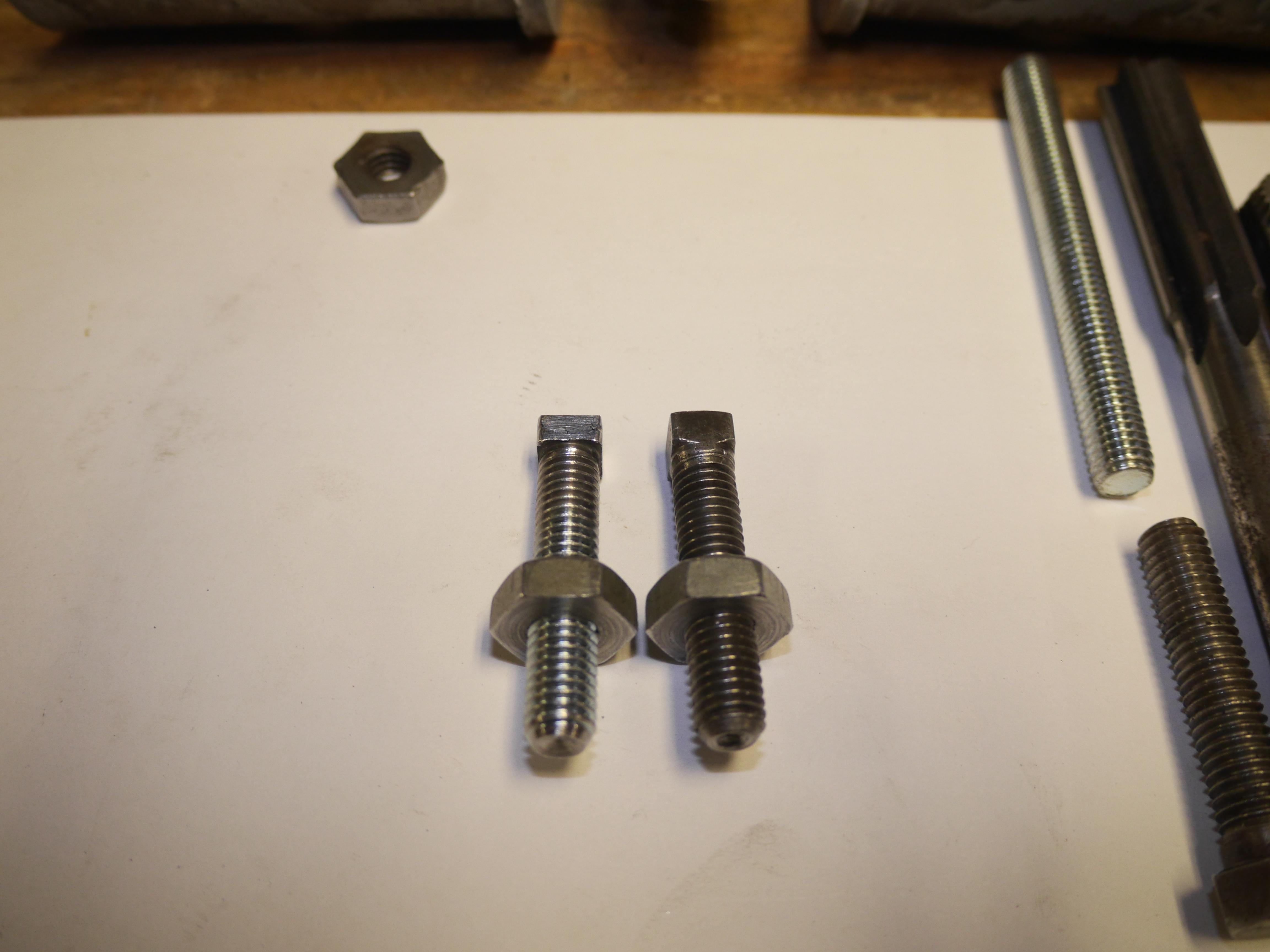
At this time I noticed that one of the special square headed cup point reel adjustment screws had been replaced with a typical 3/8-16 bolt. After looking through all of my old hardware I came up with the plan to turn a carriage bolt into the screw I needed. I turned the head off of the carriage bolt to reveal the square head, then I parted the bolt, faced it, put a taper on the end and machined a cup point into the end of the bolt. Before cleaning up the lathe, I found some oversize 3/8-16 nuts that I turned down to the appropriate thickness to act as jam nuts on the lower reel adjustment screws. Other than the age of these new fasteners everything is an identical match.
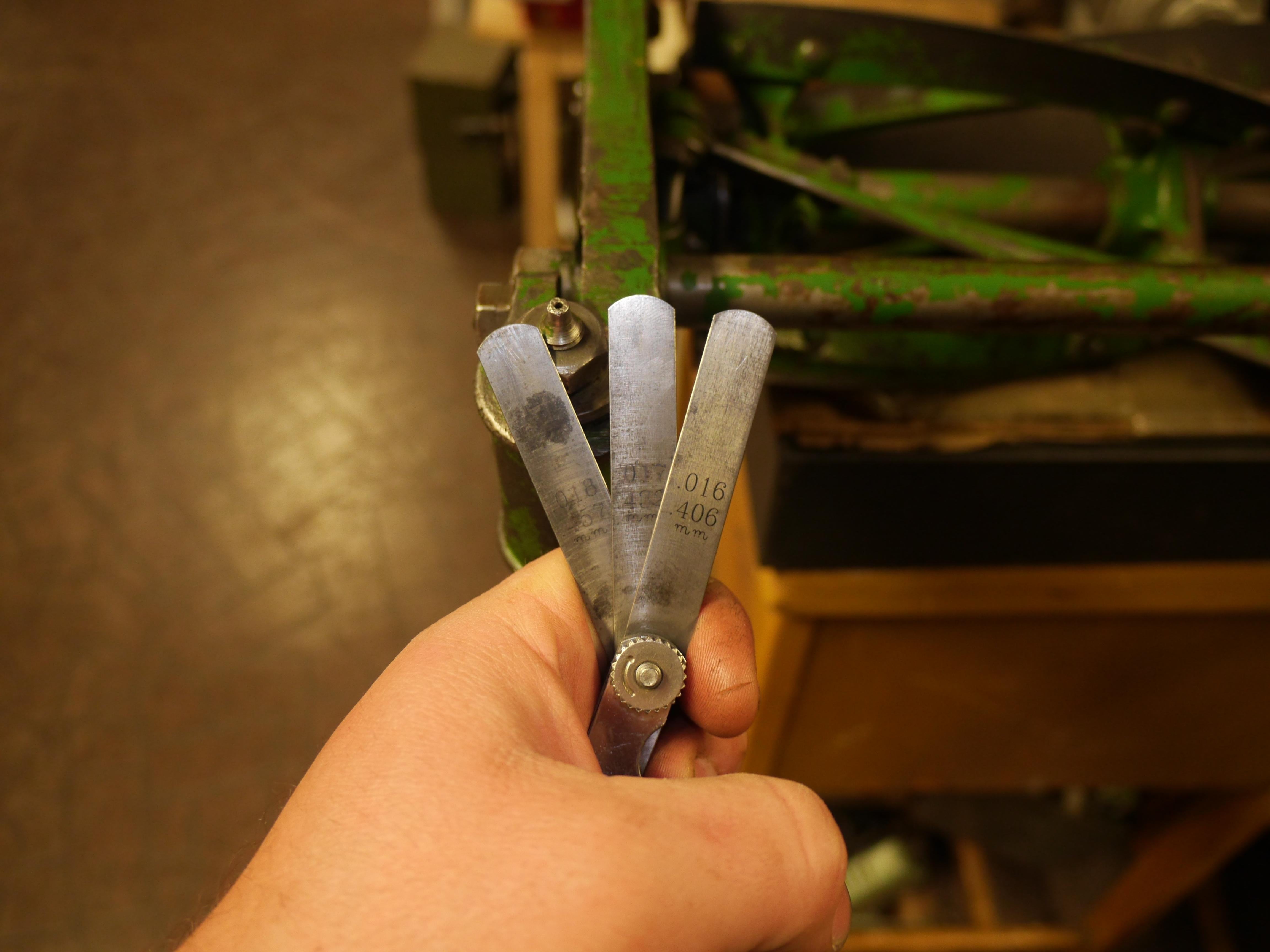
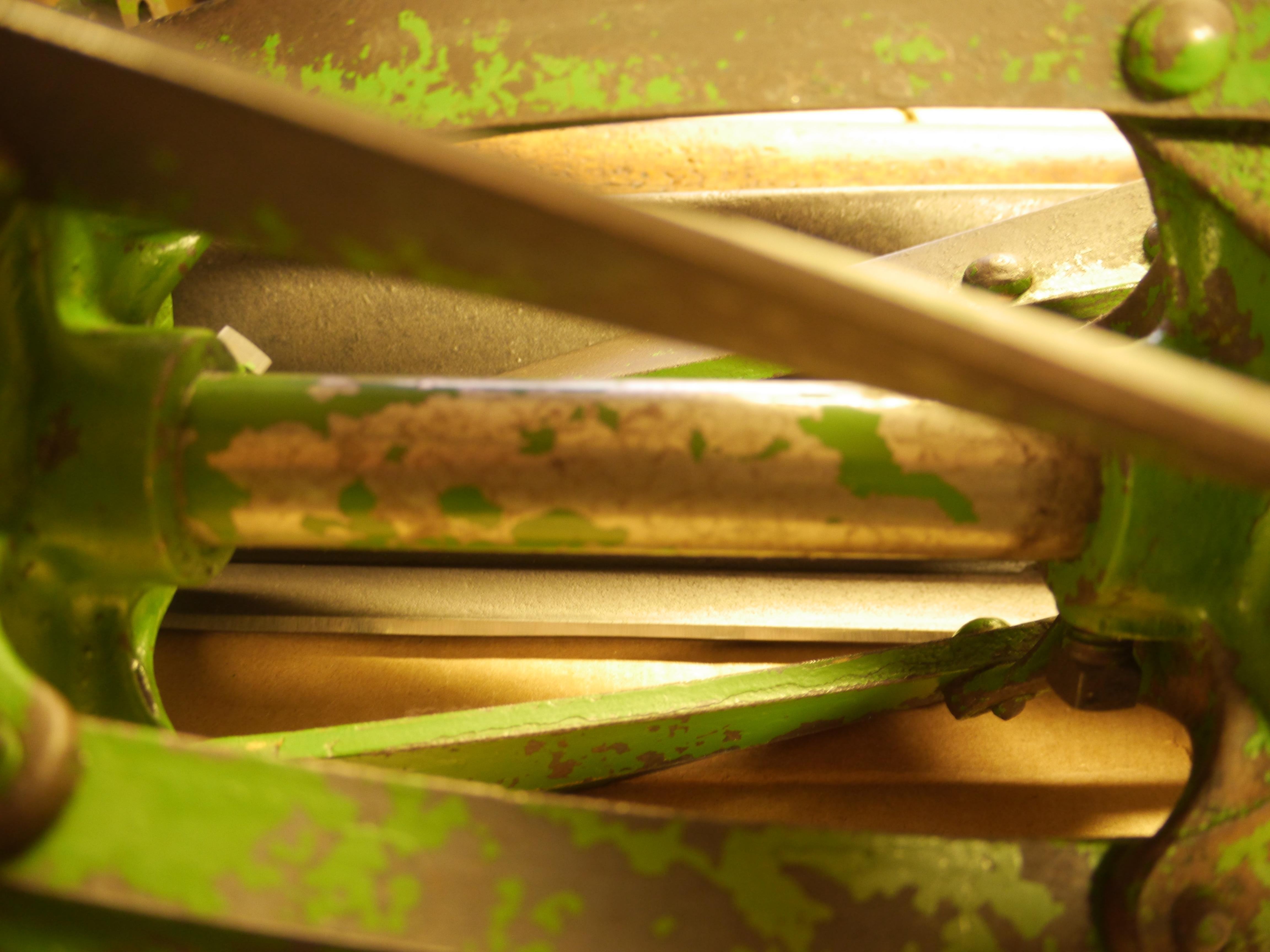
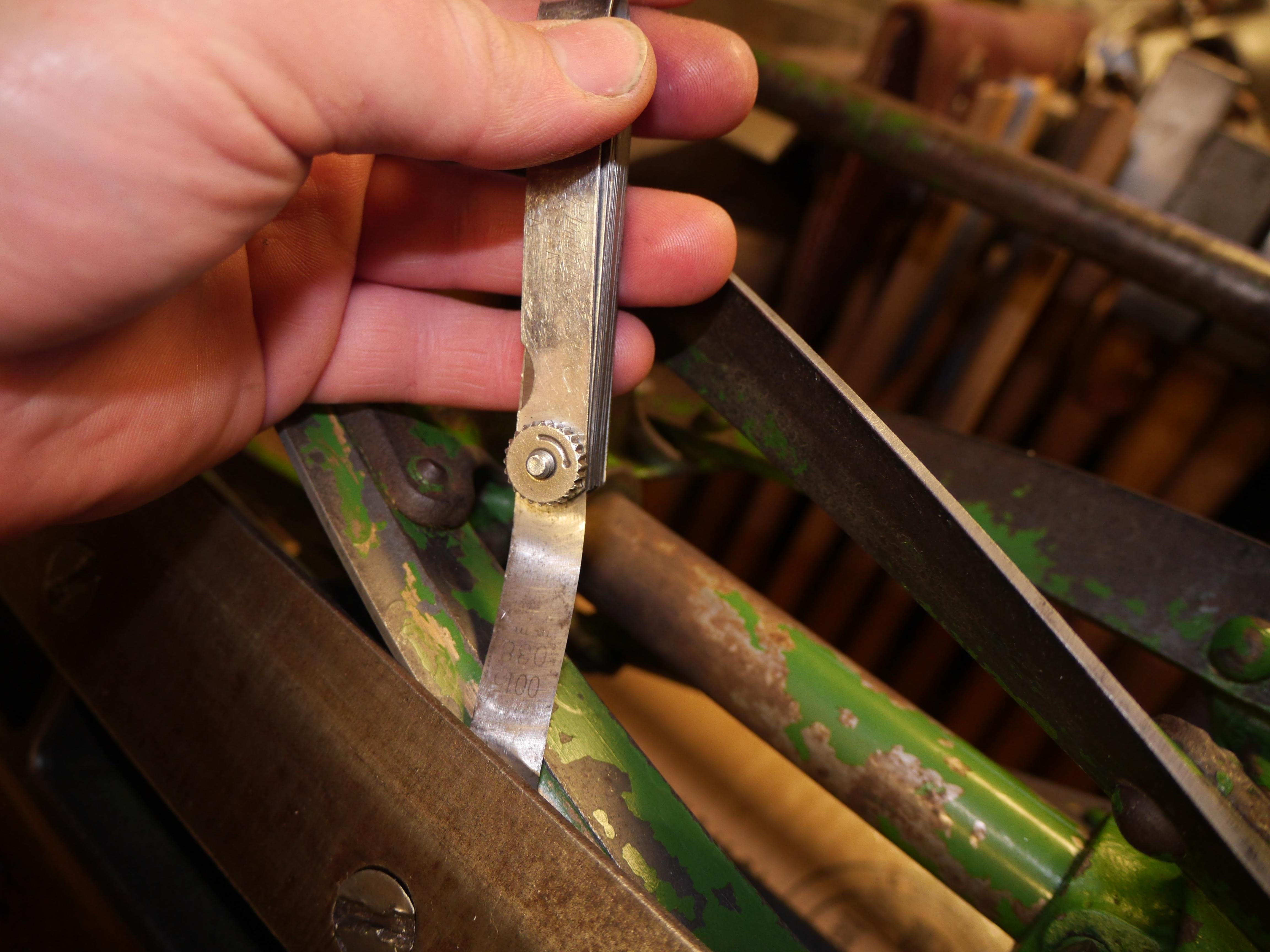
With the reel adjustment screws setup the way that Coldwell would have wanted them, I assembled the mower and began checking the reel to bed knife clearance. After setting the clearance at 0.0025” I lathered up all five knives with valve lapping compound, and I powered the reel with my drill at a slow speed. For fifteen minutes I slowly lapped the reel, feeling my progress in the drill handle. After two applications and adjustments, I finished setting the reel at 0.00015” clearance, added some more lapping compound and finished lapping the reel. After lapping the reel, I spent a good amount of time removing all of the slurry/grit. With some printer paper in hand, spinning the reel by hand proved that the reel was good and sharp. I feel confident that the mower is cutting on a good 90% of the reel knives. I may end up increasing the bed knife to reel clearance when the actual mower is put to use, but for now it seems to work just fine!
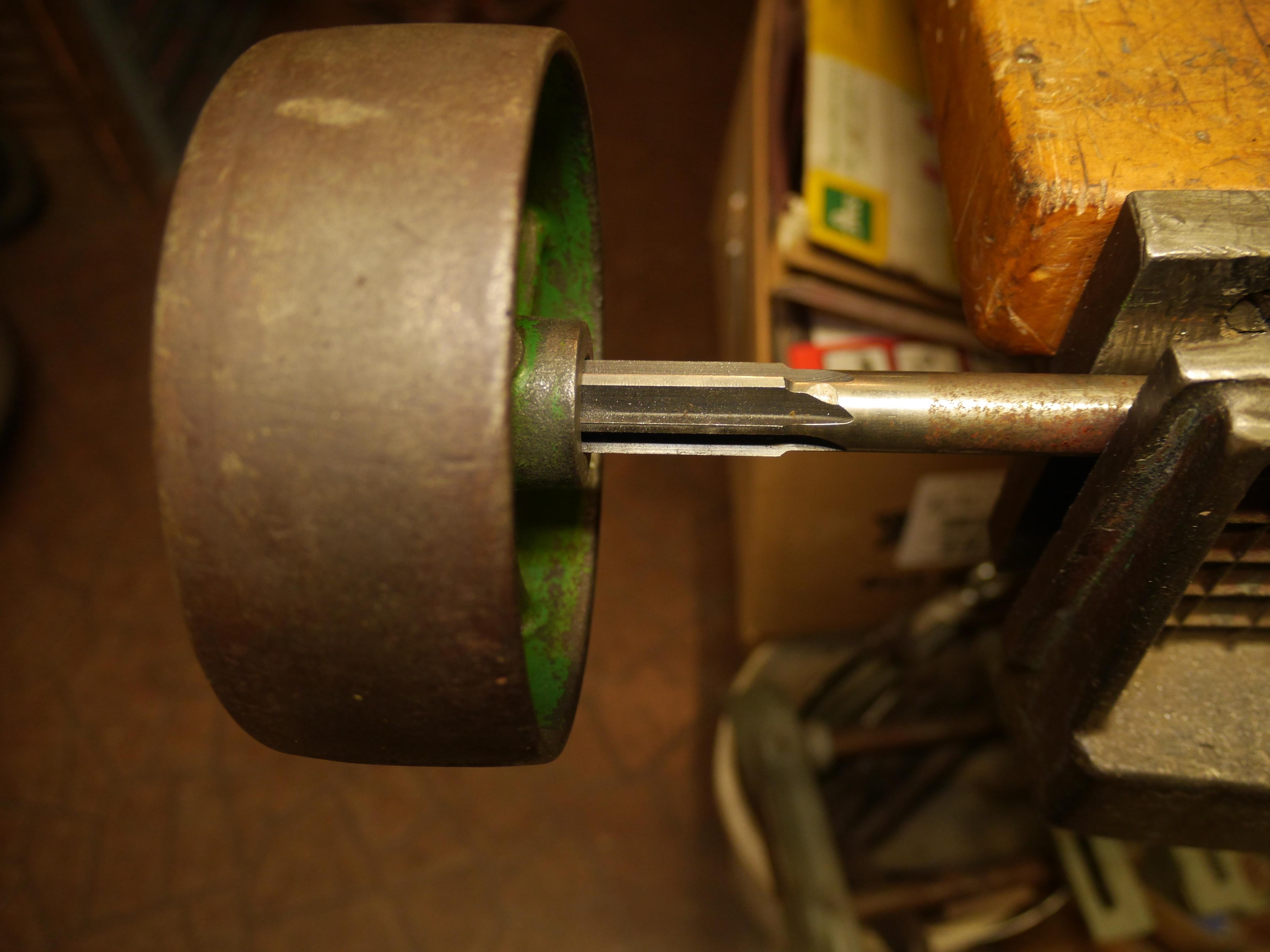
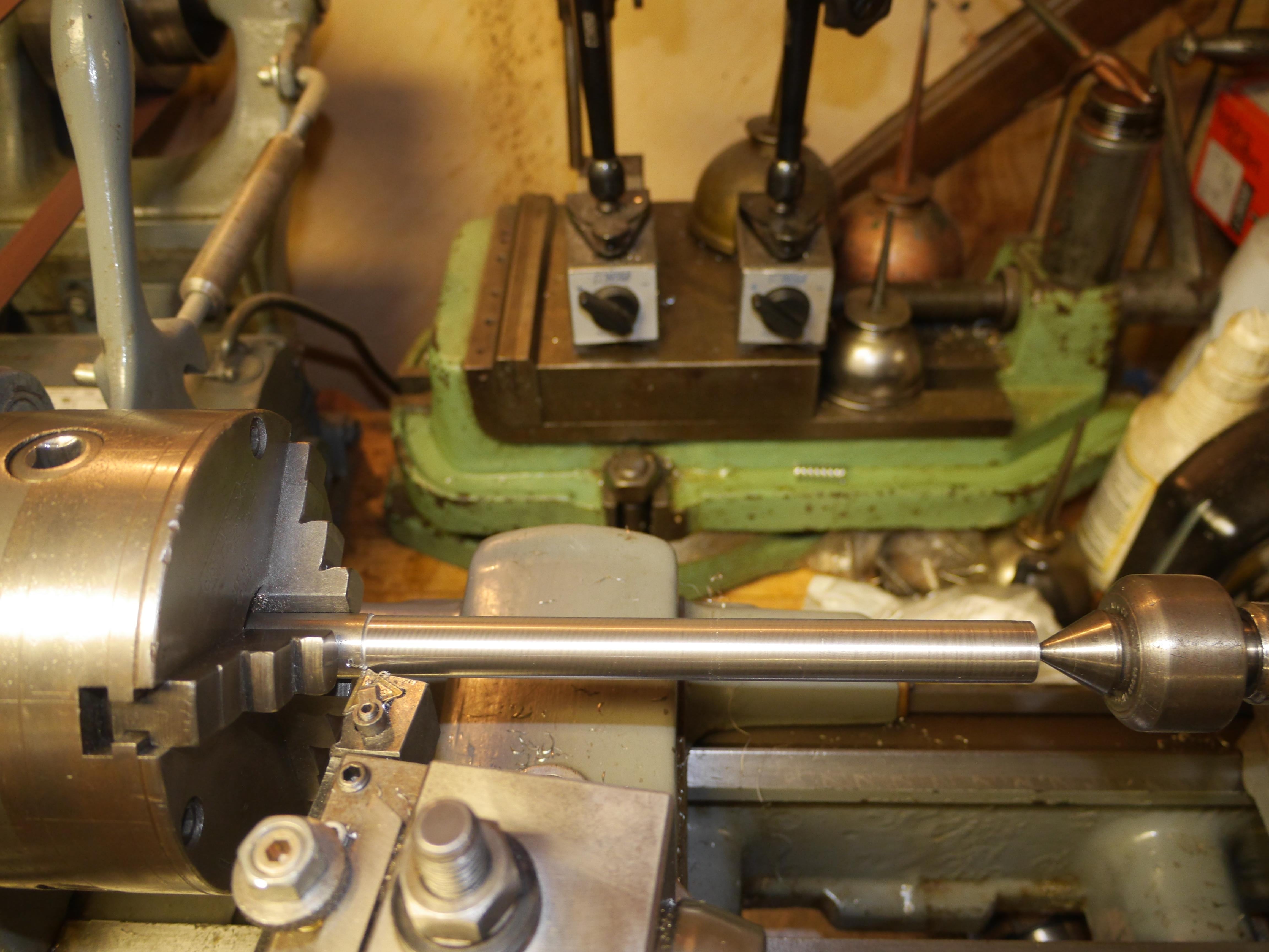
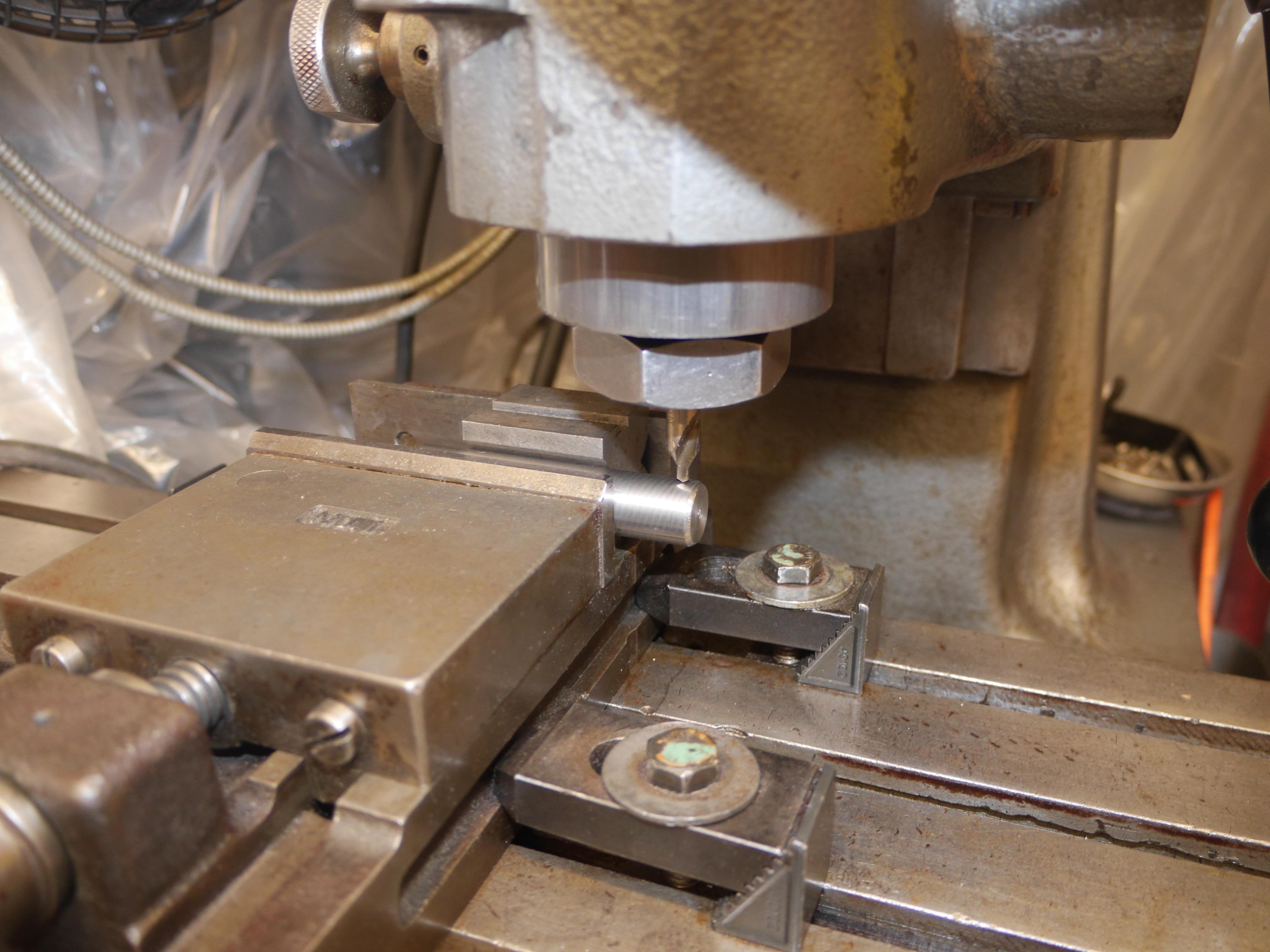
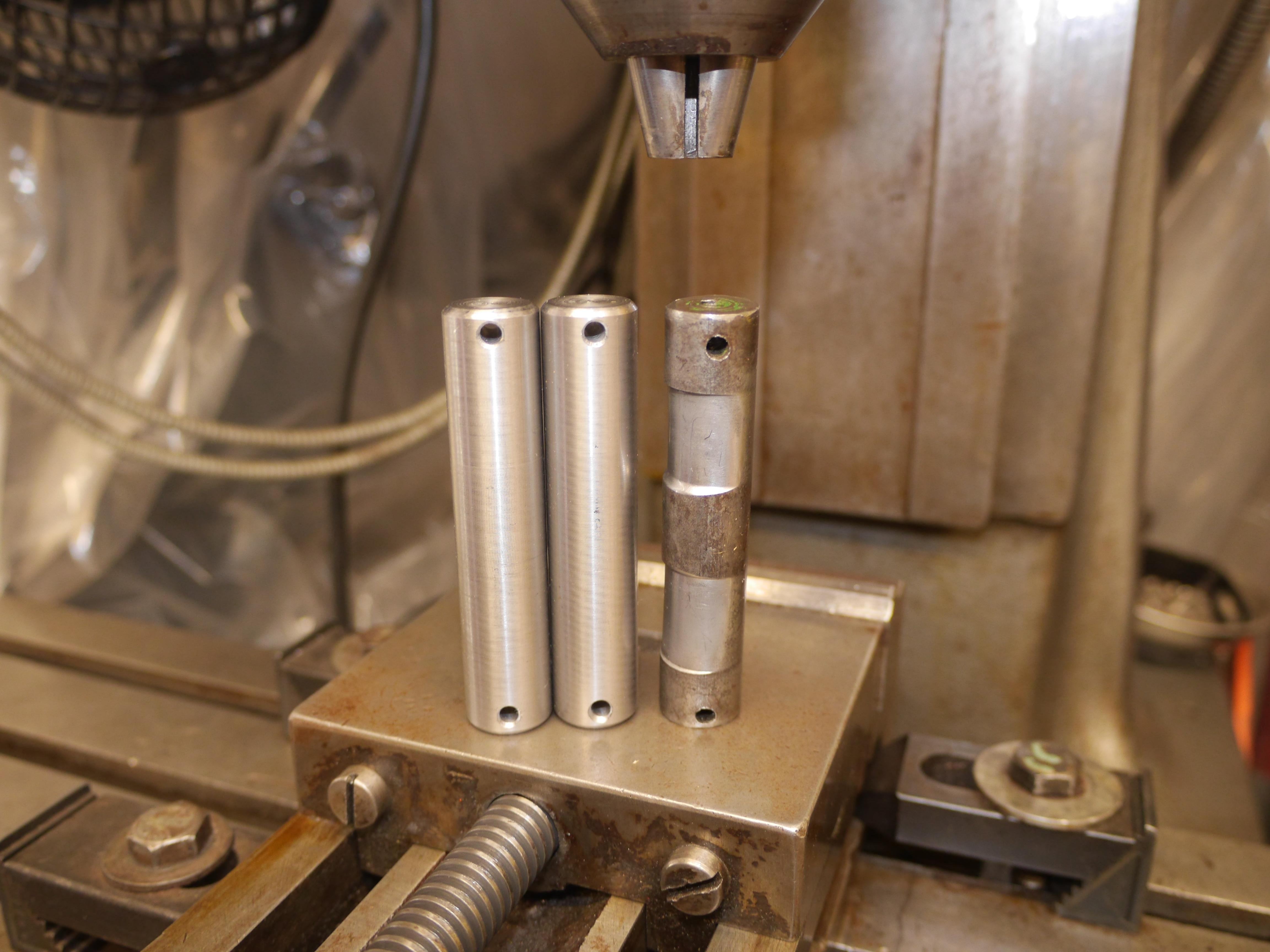
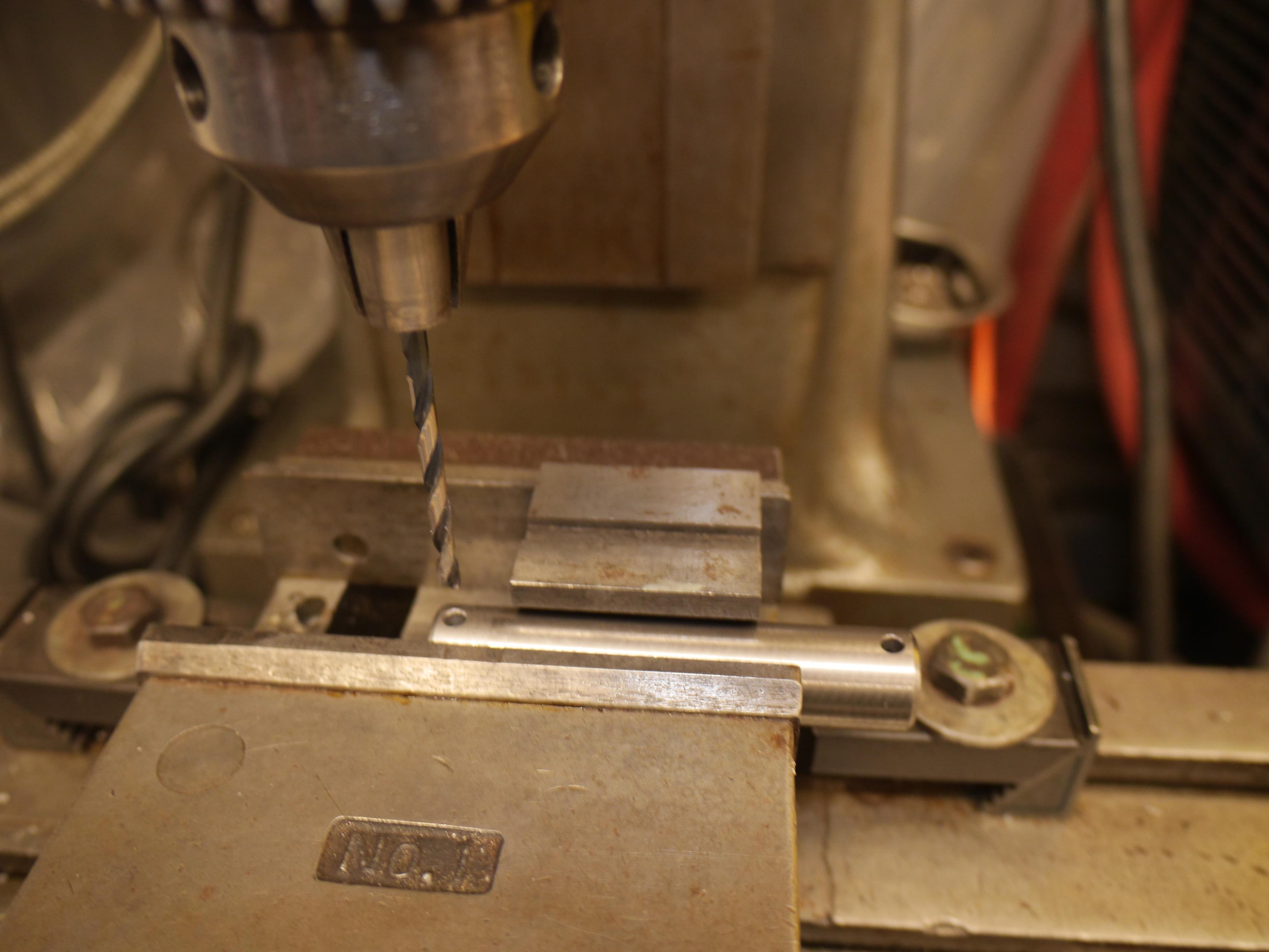
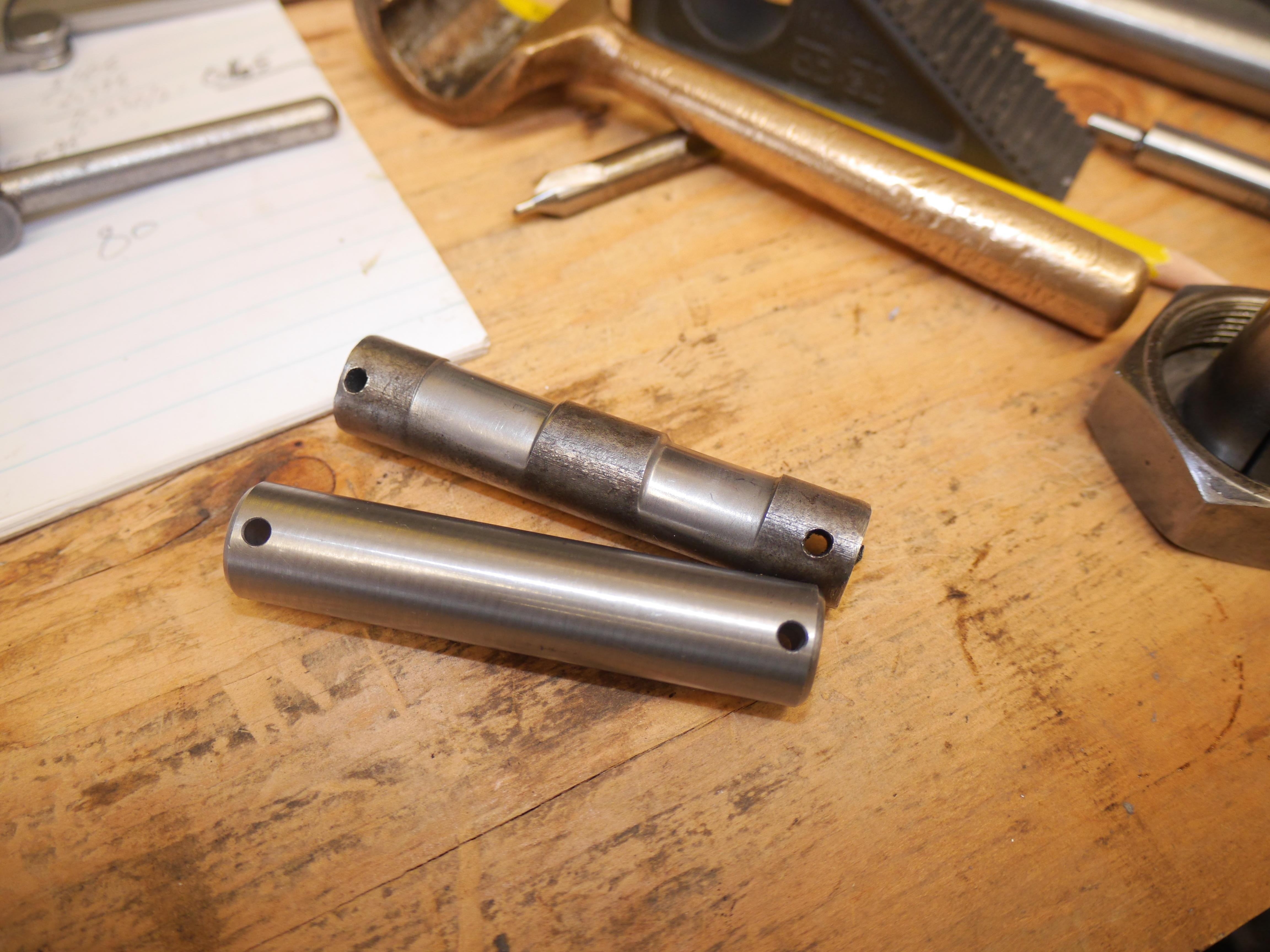
I spent some time on Sunday machining new axle pins for the two front casters. Disassembling the casters had revealed that the caster itself cut into the caster pin ~0.040-0.055”. This sloppiness also wore the bore of the caster wheels out of round. Originally these pins were 0.620” o.d., and I speculate that the bore of the caster was 0.625”. I thought about machining new pins at 0.625” o.d., but I decided to machine oversize pins. I looked in my collection of reamers and found a 0.654” reamer. I drilled the bore of the casters out with a 41/64” drill, and finish reamed the casters to 0.654”. I turned a piece of ¾” rod down to 0.650”, parted, and chamfered the edges of the new pins. With the Sheldon jig borer, I cross drilled the pins with a 9/64” drill bit. The new pins came out fabulous. The built in 0.004” clearance will be just right to establish a grease film.


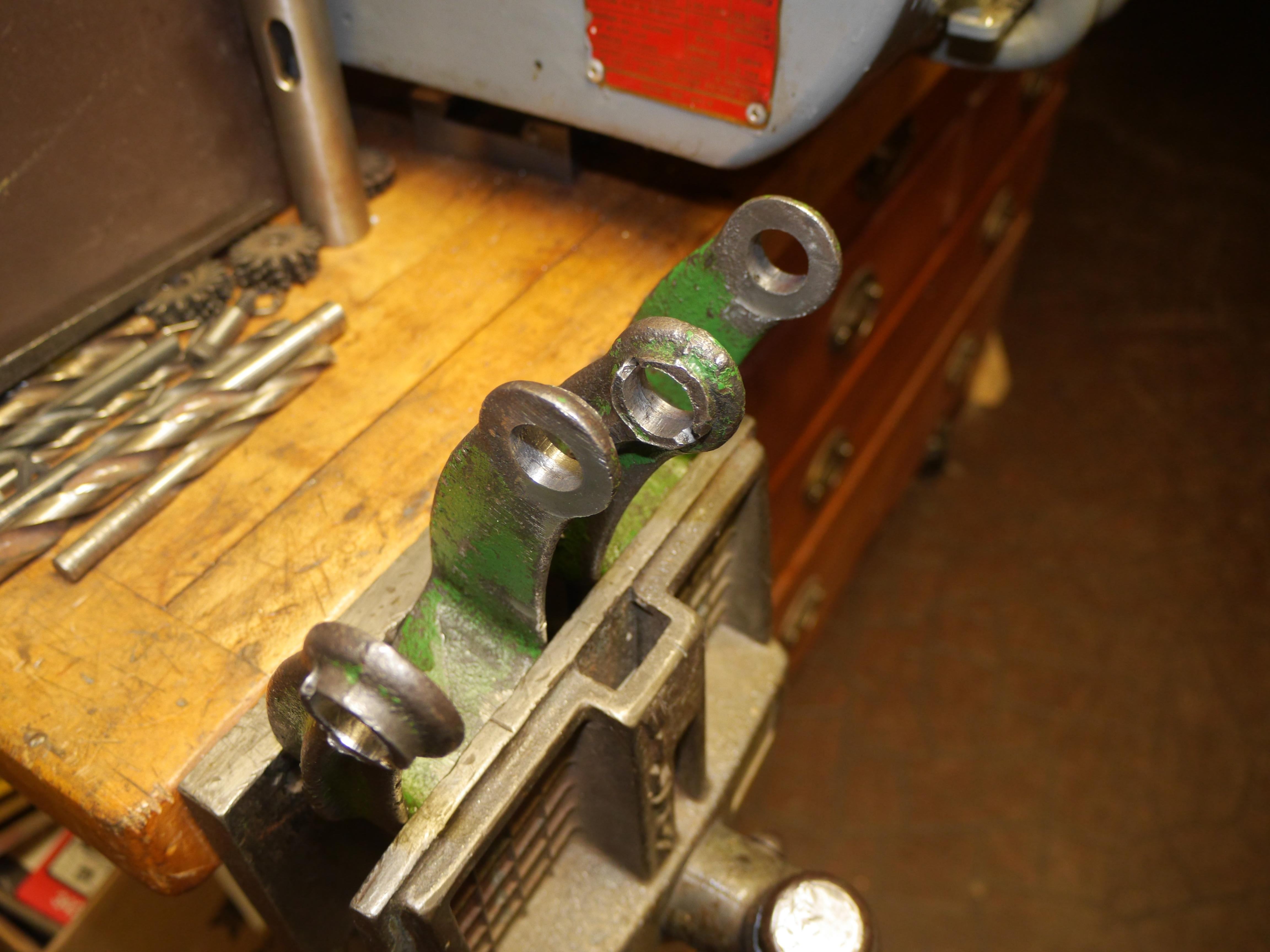
With the new axle pins made, I took a good hard look at the spindle forks, and discovered that both were extremely warped. I was honestly ready to throw in the towel. I looked both spindles over under a magnifying lens and I did not see any cracks anywhere. How they bent so out of whack is a real mystery. With over 3/8” of twist in the one spindle fork I realized that if these spindles were in cast iron that they would have simply cracked. I filed a few burrs on the spindles and realized that they were cast steel. I mounted the spindles in my soft jaw vise one at a time and with a 3ft long ½” rod I began applying some pressure to un-twist the spindles. That actually worked okay. While holding pressure on the rod, I began tapping the spindle all over to help relieve some surface tension. After about four hours I was able to slowly straighten both spindles sufficiently without breaking anything! I finish reamed the bores to size and checked the fit of my new axle pins. These new pins helped me visually check the straightness of each spindle. I would say that they are now ready for another ninety years of service! I could not be happier. I now have well over two hundred and fifty hours into mechanically restoring this mower, and I still have a long way to go, but it is certainly getting there. It is hopefully going to be the nicest original 1931 Coldwell Cub out there when I am done with it.

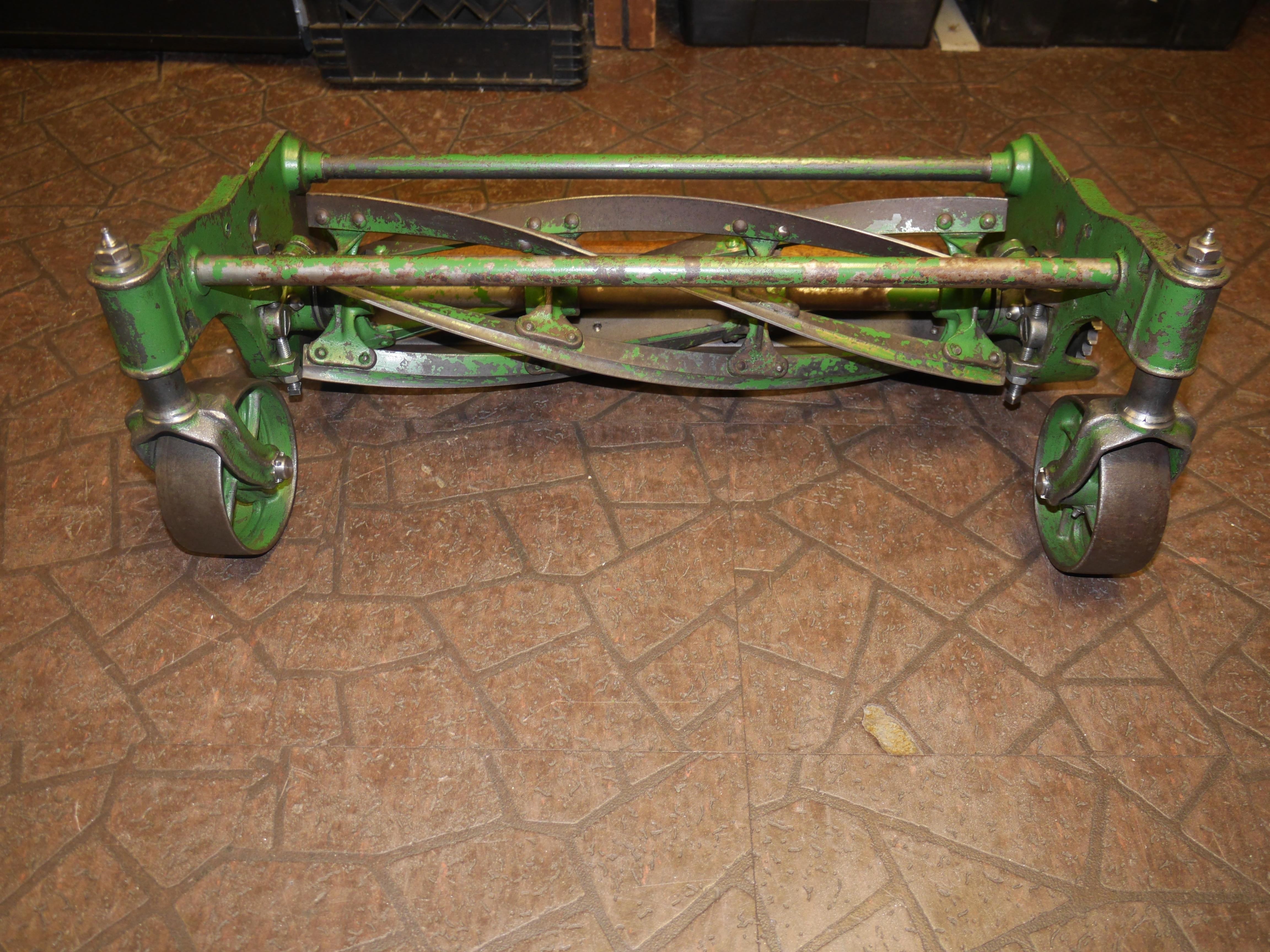
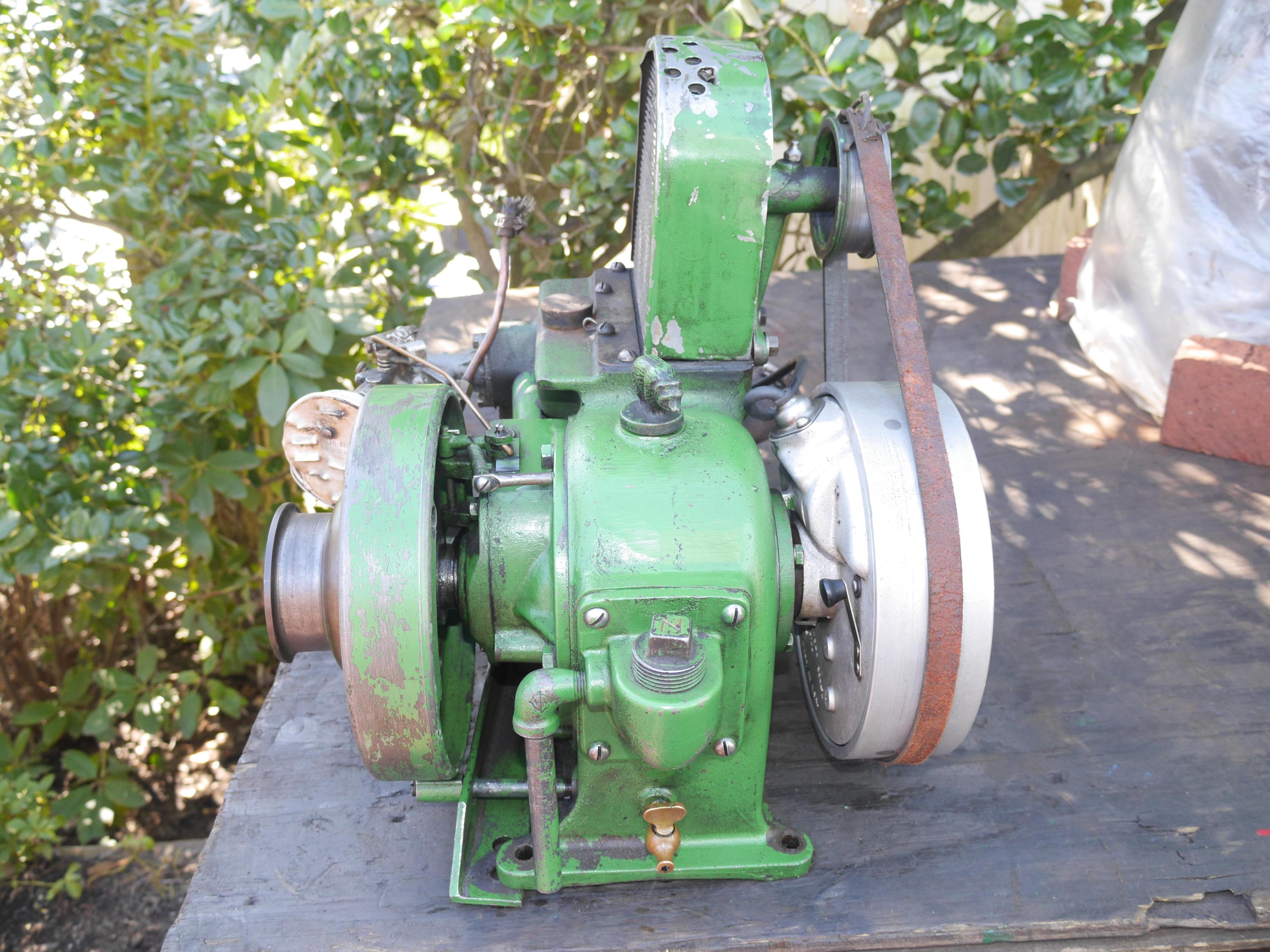
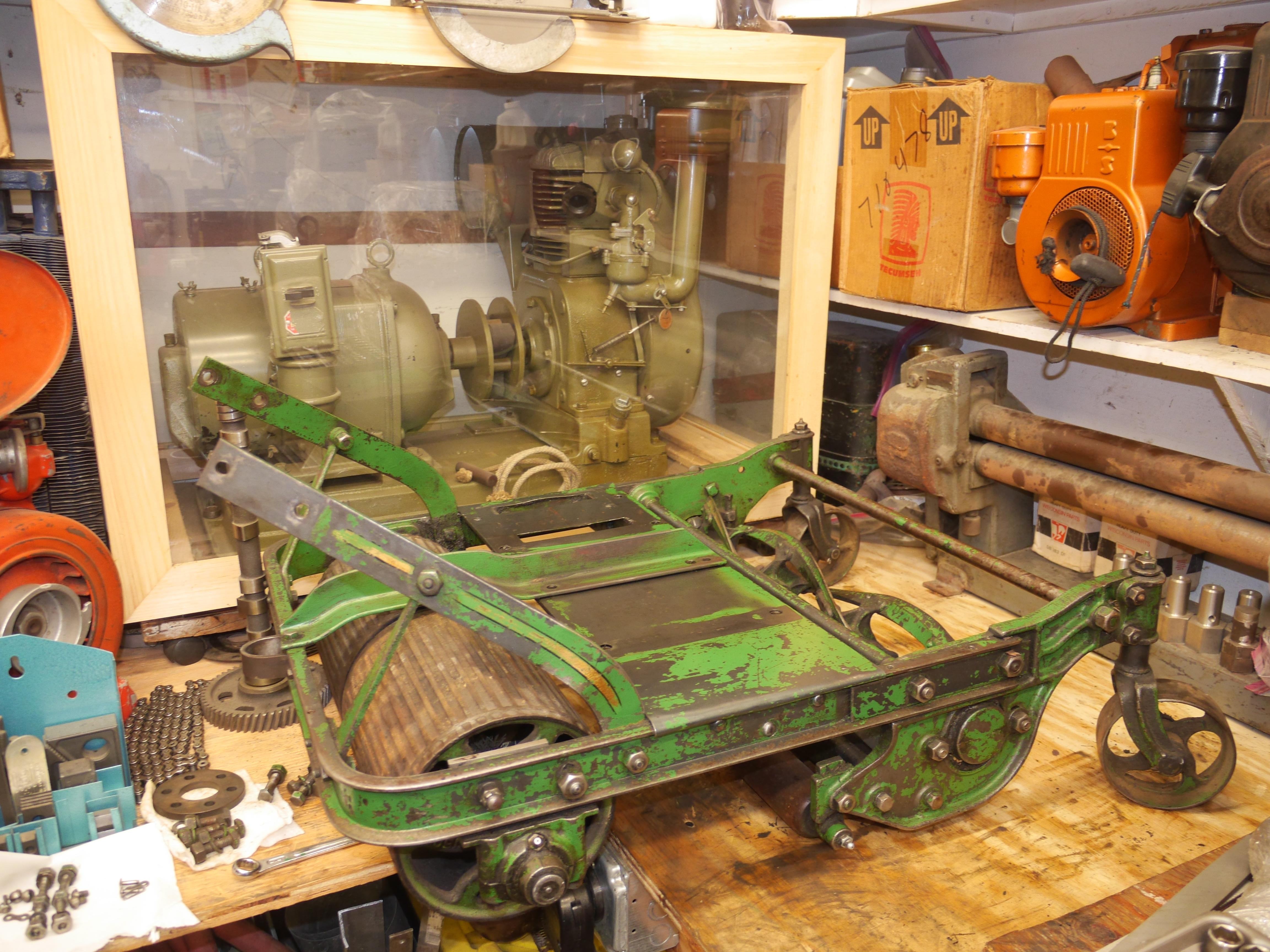
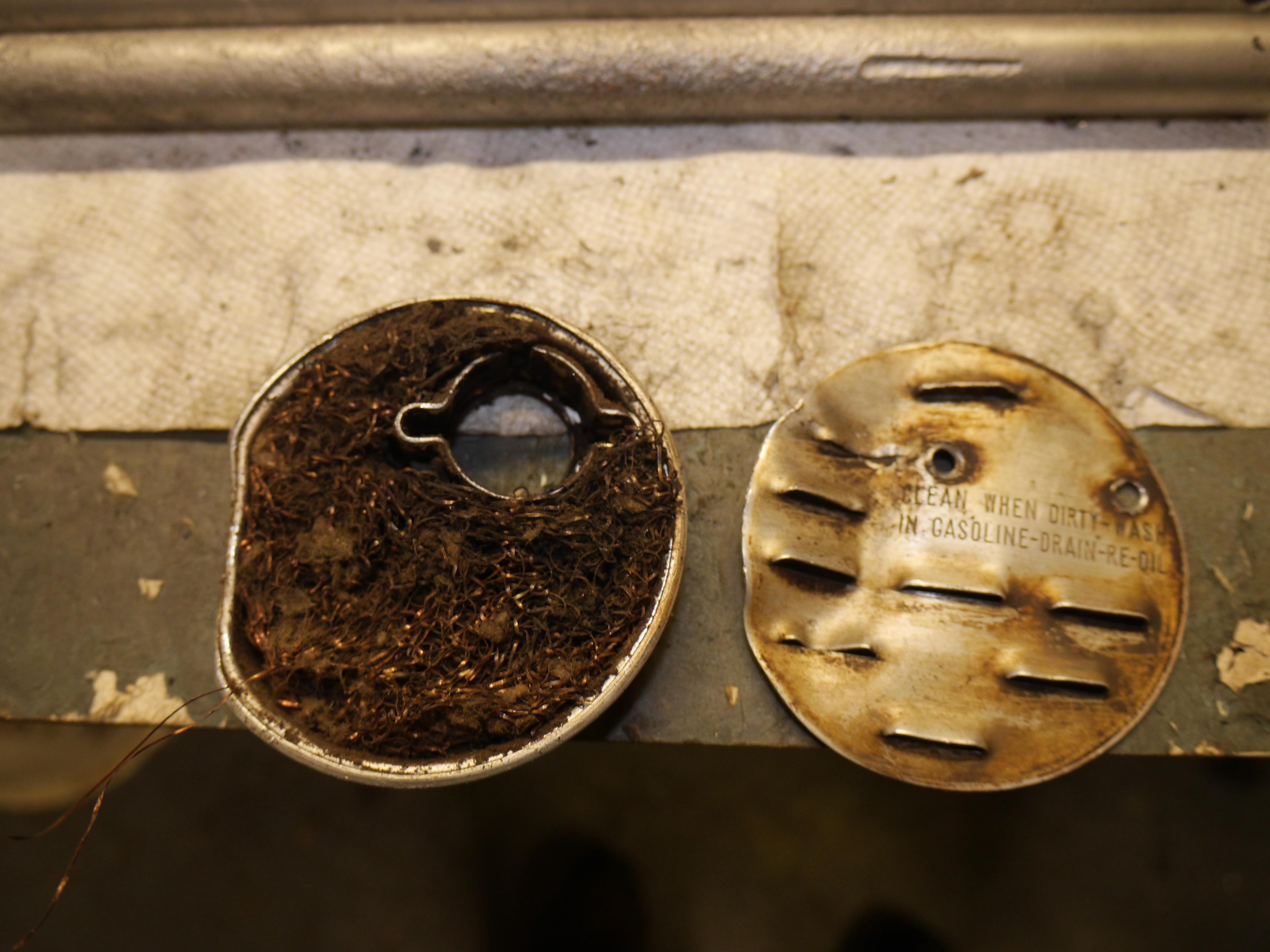
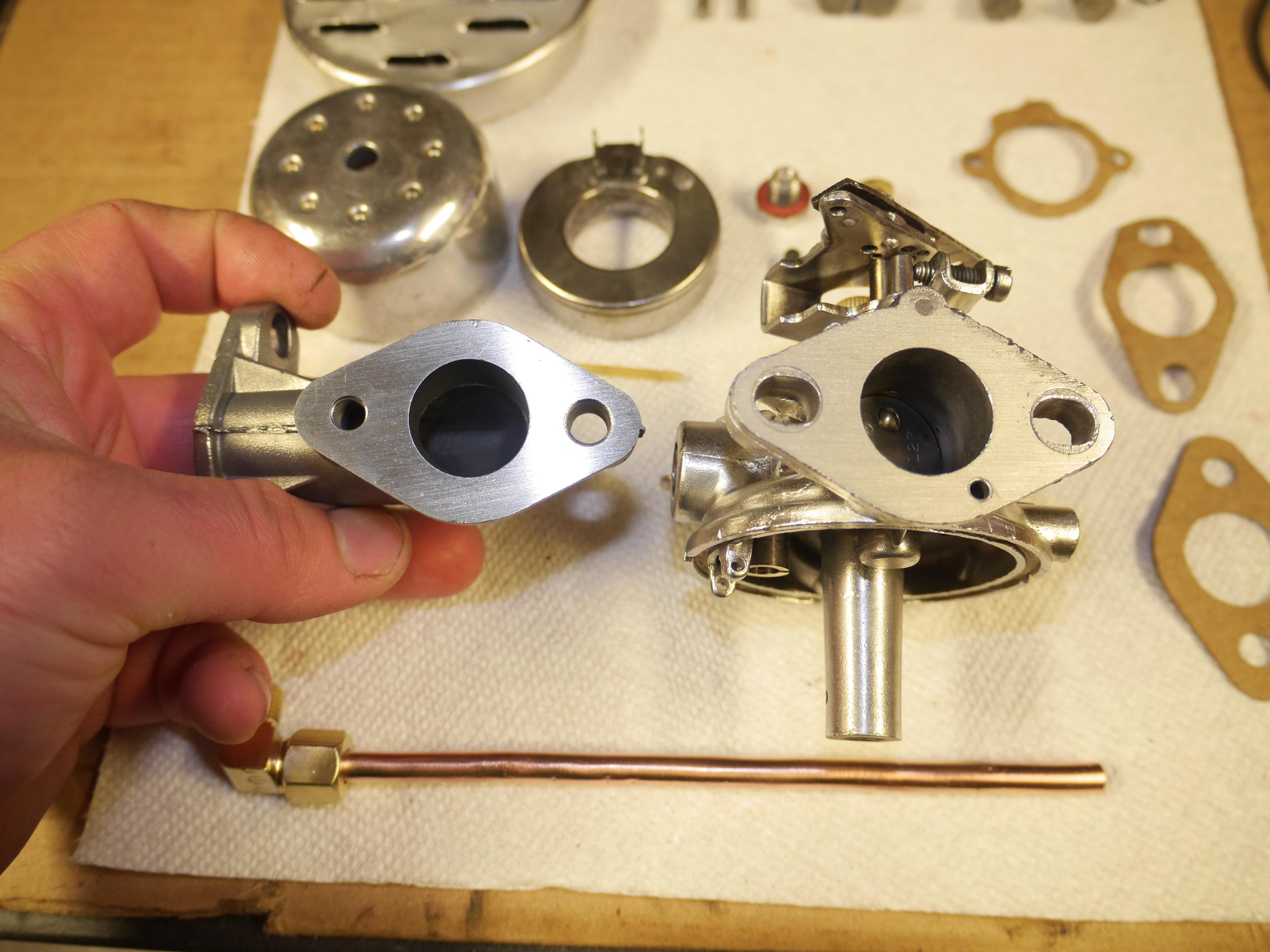
I have been totally consumed by the Coldwell project and have several more updates for you. The mower deck is mounted back on the machine, and a list of things to do has been established. I started out by cleaning up the belt driven cooling fan. It operated with a continual soft squealing sound despite some fresh grease applied. I found more hard packed grease to be the culprit. I also discovered that the cast iron fan housing was not machined to accept a replaceable brass bushing. Instead Coldwell poured brass inside the rough casting, machining the i.d. to size afterwards. I thought that was pretty unusual. There was no major wear to be found. The three blades of the fan were actually quite bent. It took quite some time to carefully bend and indicate the three blades until they ran nice and true. After mounting the straightened cooling fan back on the engine I began working on the front reel guard. Some of you had inquired about the reel and reel bearings. Some Coldwell literature I have calls the reel bearings Hyatt bearings, and Coldwell says that the reel is oil hardened tool steel. The reel guard was in really nice shape, but it had a bow to it which I spent several hours gently correcting. Everything is now nice and true as it would have been when this mower left the factory. I took some time to properly adjust the mower deck to obtain adequate chain tension, and make sure that the reel was perpendicular to the mower for a perfect finish. With these parts finished, I decided that I might as well ultrasonically clean and rebuild the Carter model N carburetor that was used to replace the Tillotson MS31D. It had to have run well enough with that carburetor to accumulate the hours that this mower has on it. The carburetor itself was in fairly decent shape, although the throttle shaft and choke shaft have been modified to work on this mower. I found out that this specific carburetor was not for a Continental AU85, but a Clinton 900 engine. I was surprised to see an aluminum float in it. The carburetor came out really nice. The air cleaner also came out really nice. It had been smashed in pretty good on the one side.

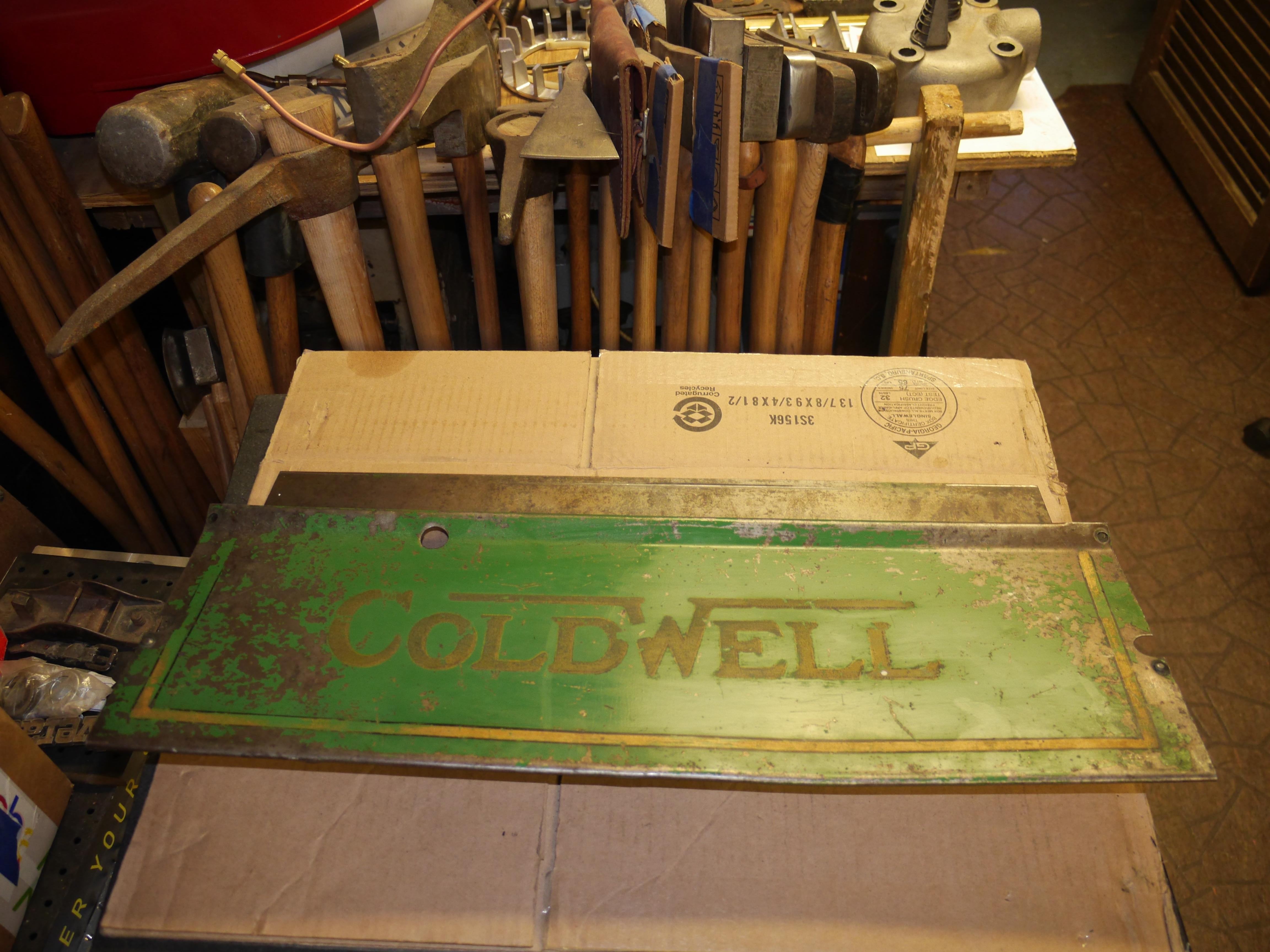

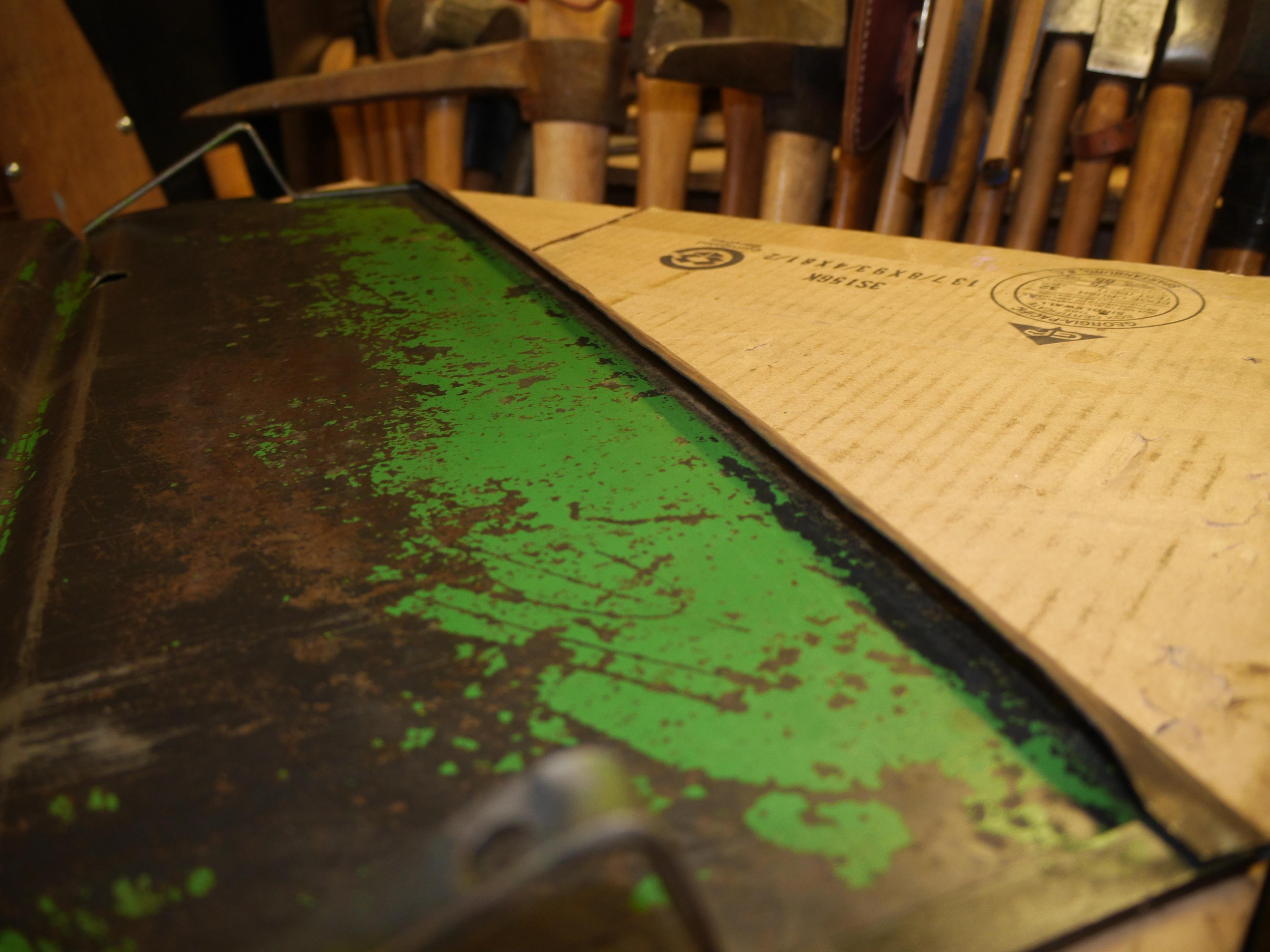


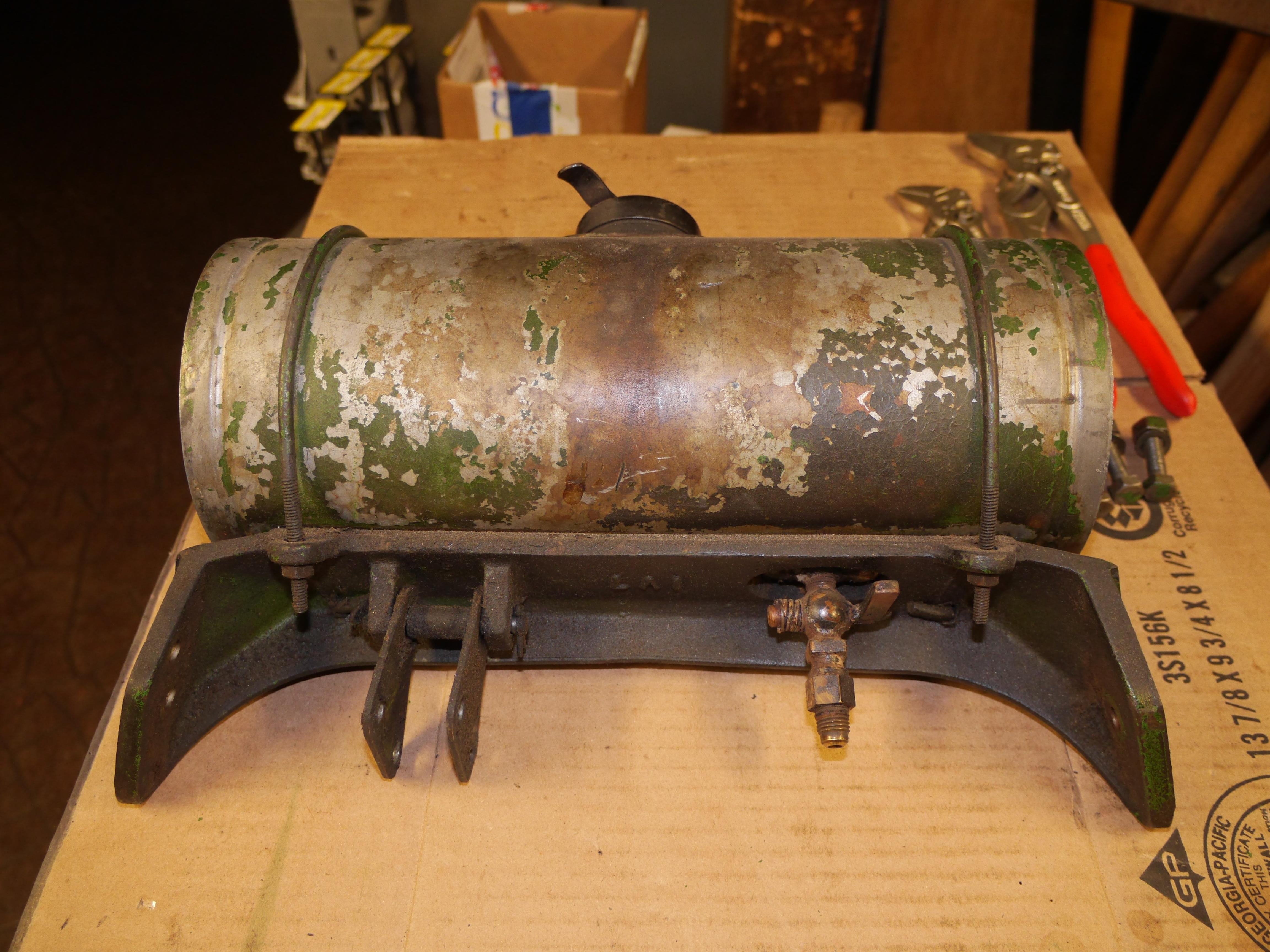
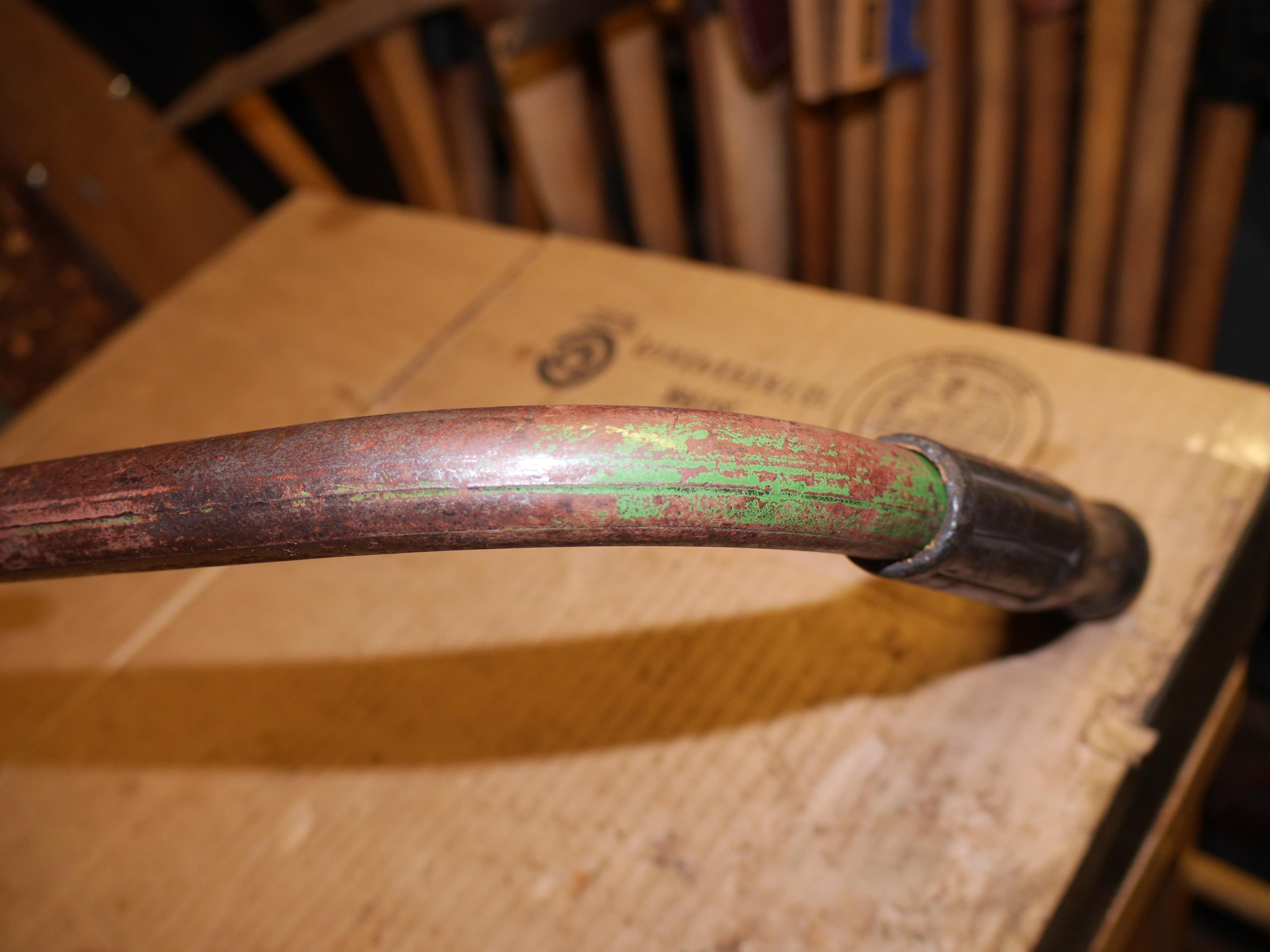
With the carburetor all cleaned up and rebuilt, I decided that it was time to clean the fuel tank and the handlebars. I had previously cleaned the handlebars, but not as well as the rest of the mower. Underneath some of the grease and rust I found some more pin striping and gold leafing. I was surprised how much of it cleaned up. The paint on the gas tank was a real mess, with dirty stained paint all over it. I carefully cleaned and swabbed the tank for four hours to bring out some of the nice green paint and graphics. I discovered three small dents at this time, and was able to push them out with various lady slippers. At this time I also came to the realization that this tank had not been de-soldered or cut open on the one end that is missing the factory painted decal. The solder seam is too professionally done, and the tank shows no sign of anyone being inside of it in ninety years. The tank is internally galvanized so it did not take very long to clean it out. I am going to do my best to recreate the missing graphic, as the bare spot sticks out like a sore thumb. Lastly I wanted to mention how overbuilt these handlebars are. The handles are heavy gauge steel pipe that will not break under any normal operation. In fact I utilized the handlebars to lift the four hundred pound mower onto my work table without any issue. My Eclipse power reel mowers on the other hand have handlebars so thin that they flex near failure under normal use. Clearly value engineering did not exist when this Coldwell was made!


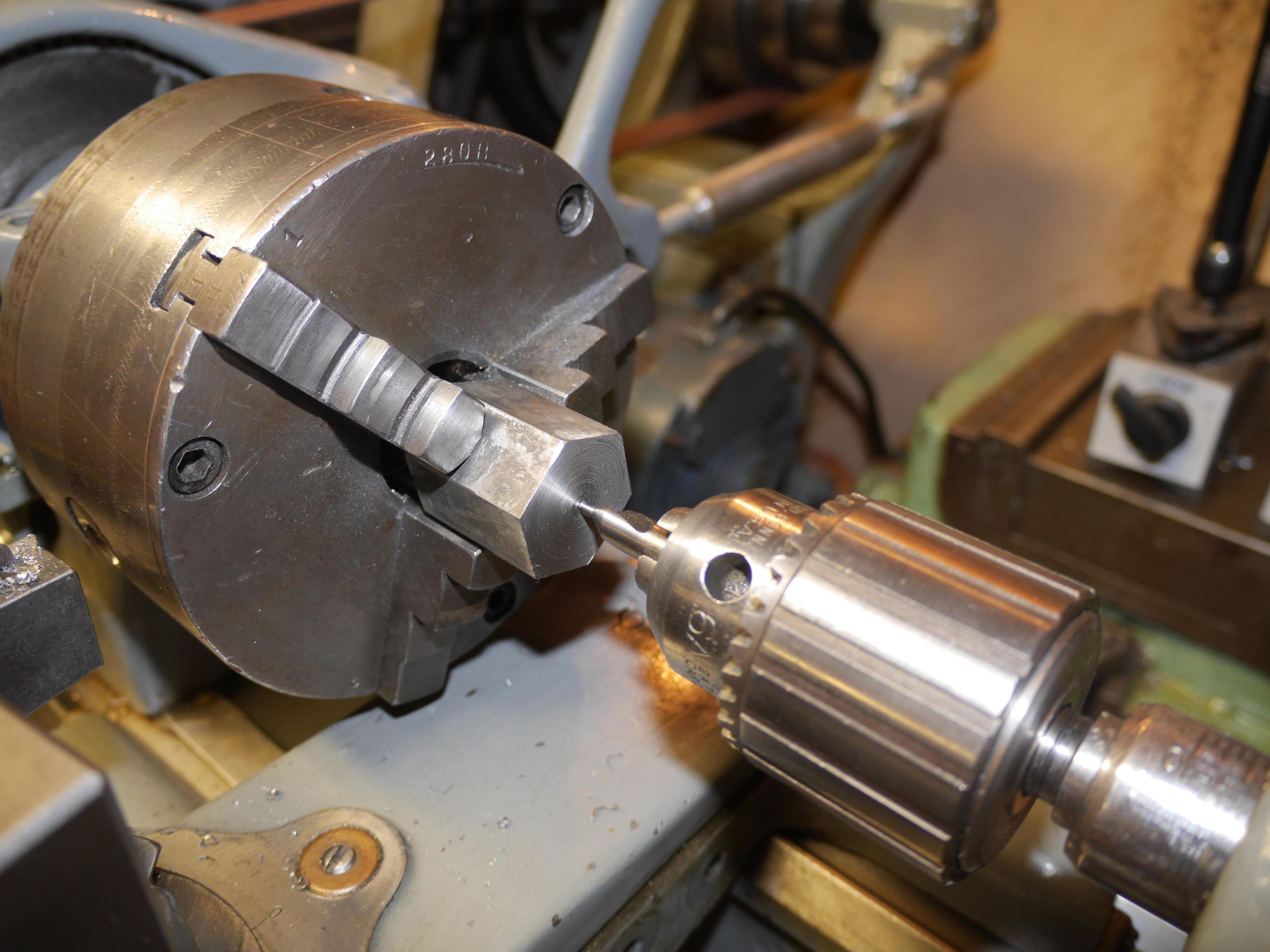
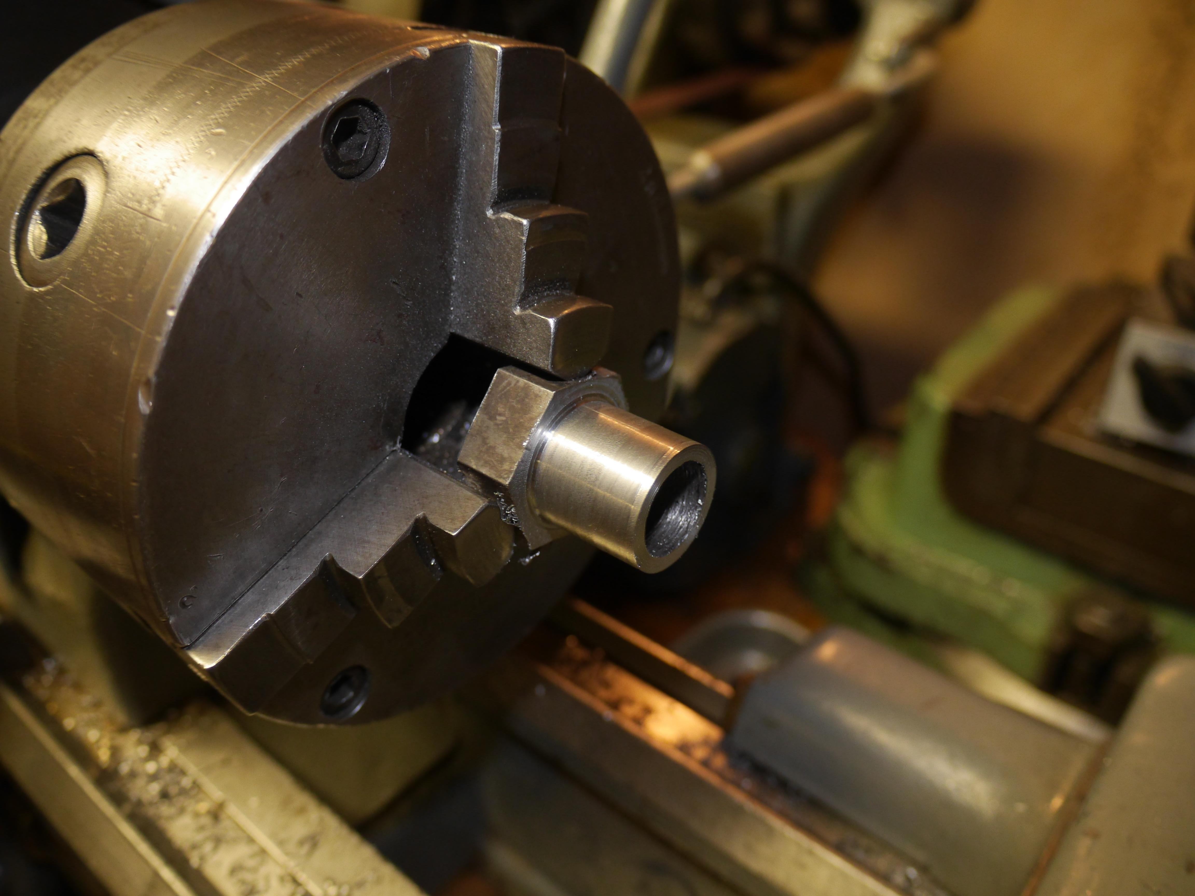
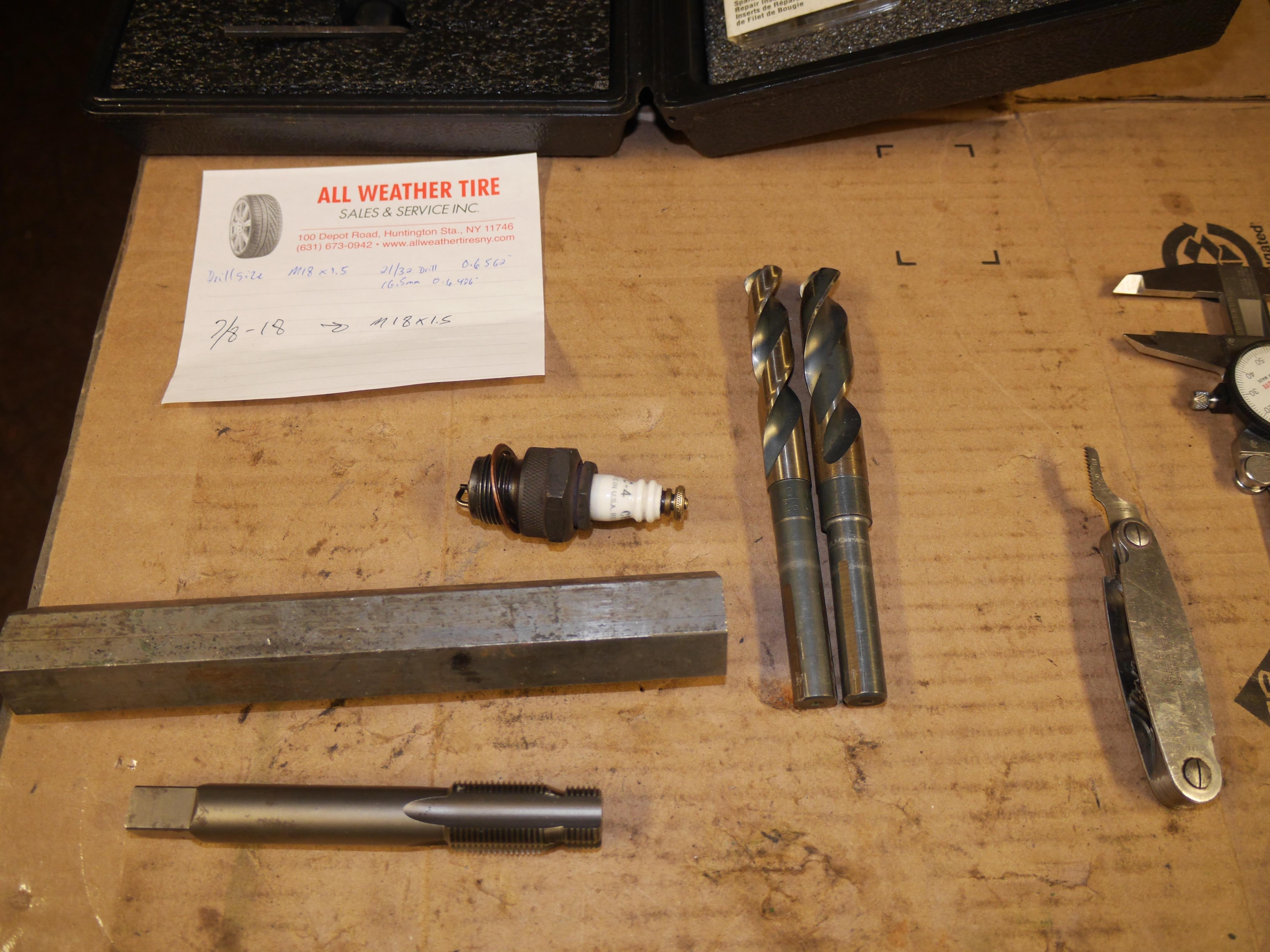
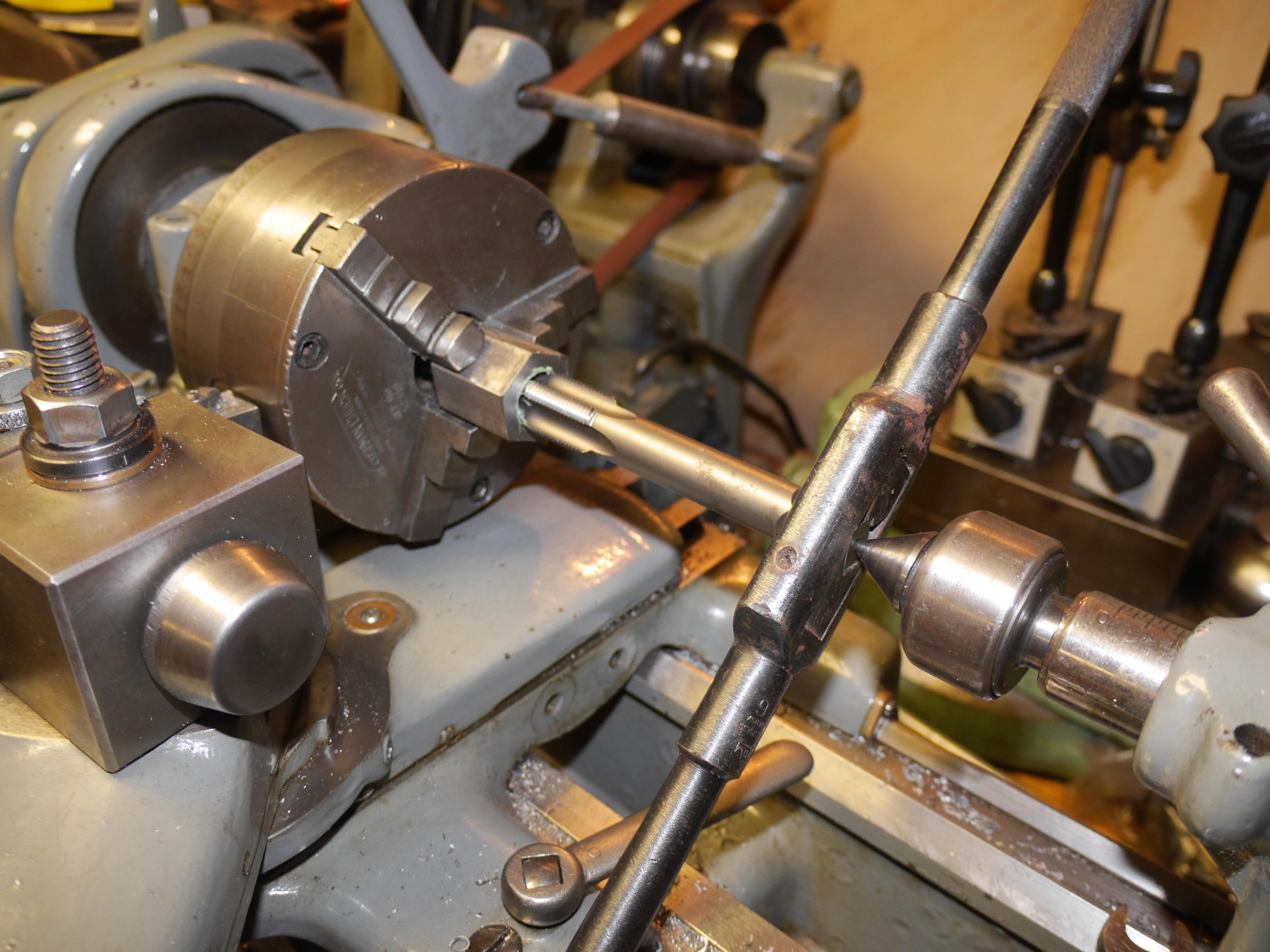
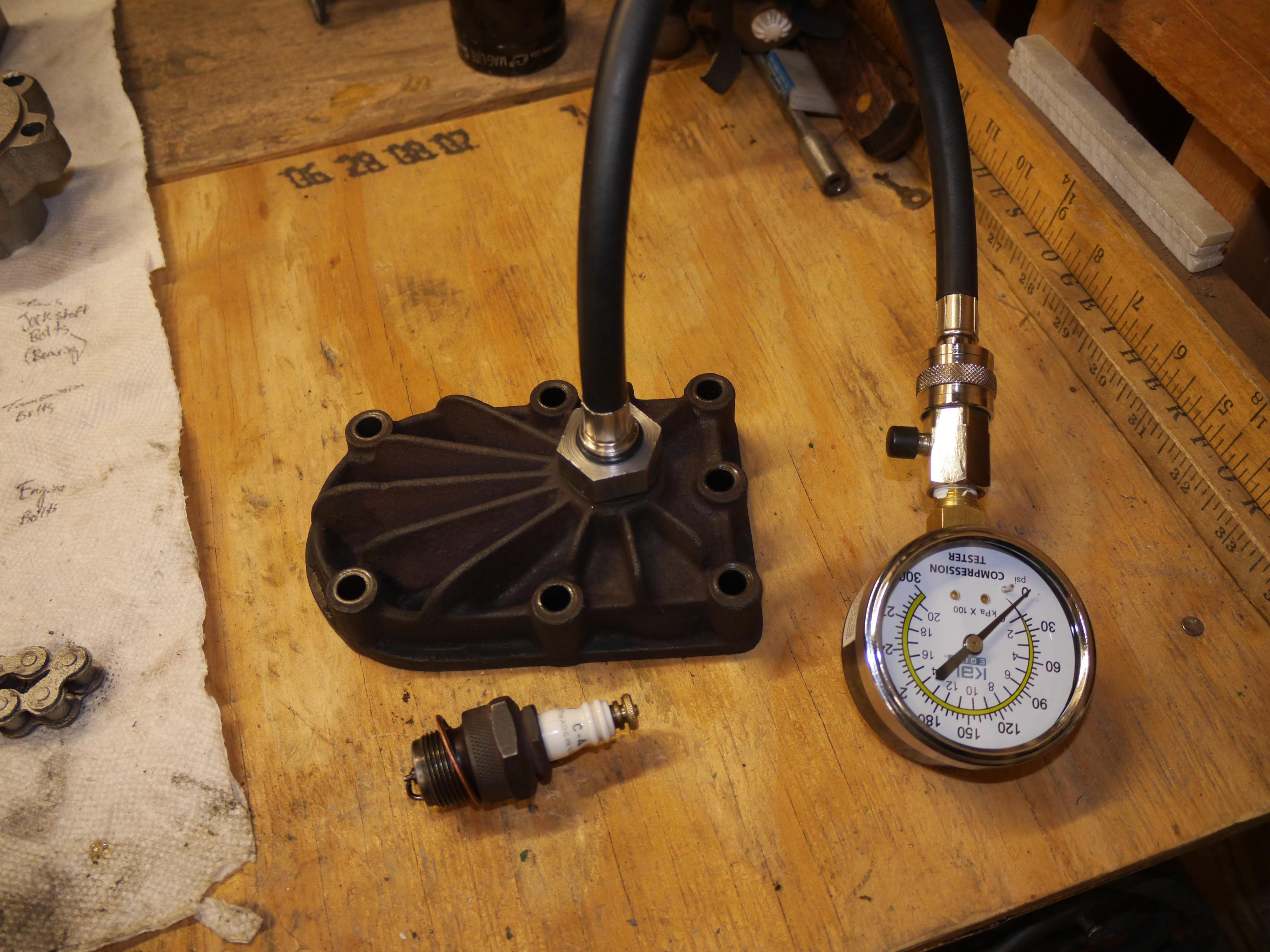
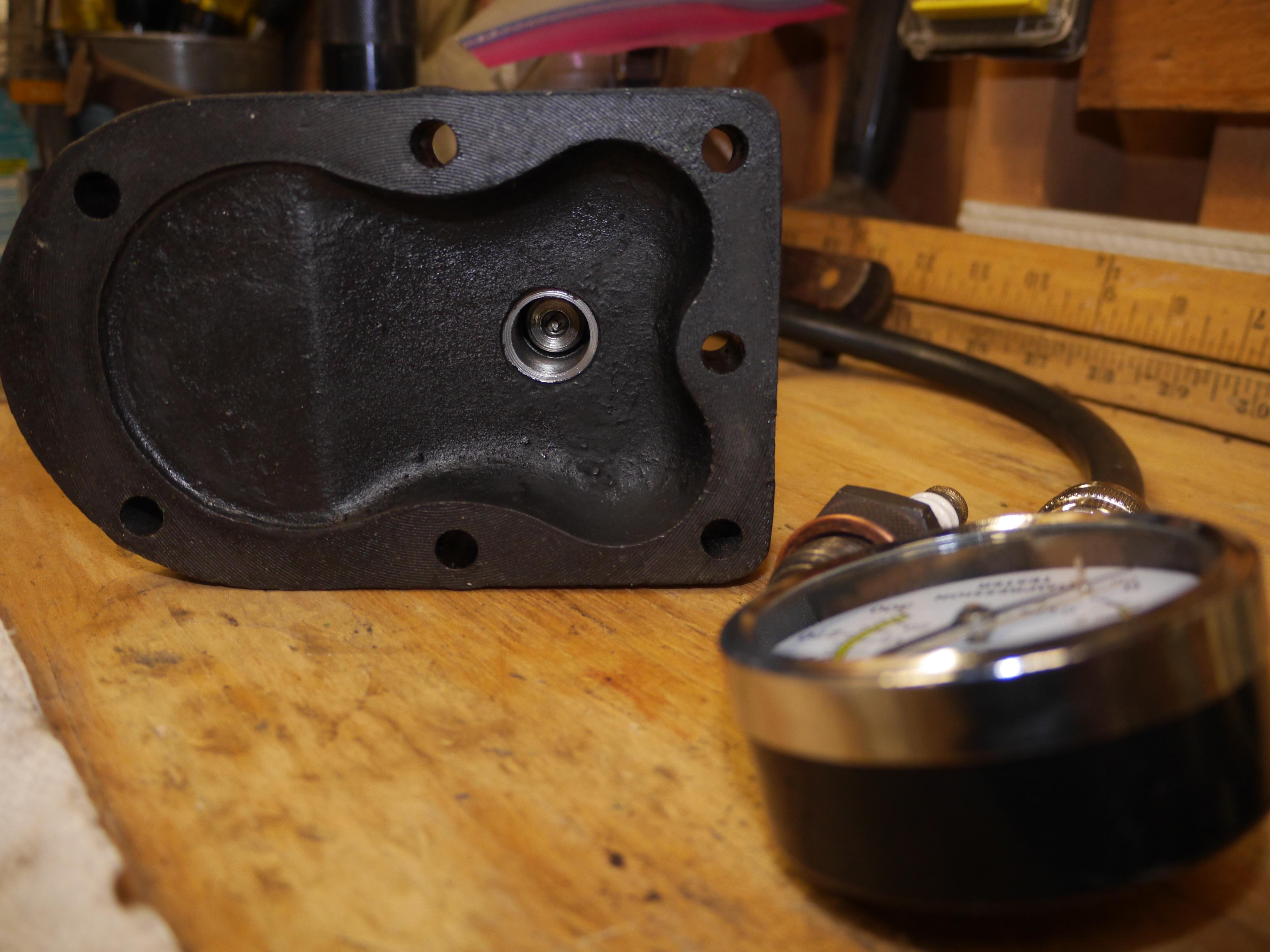
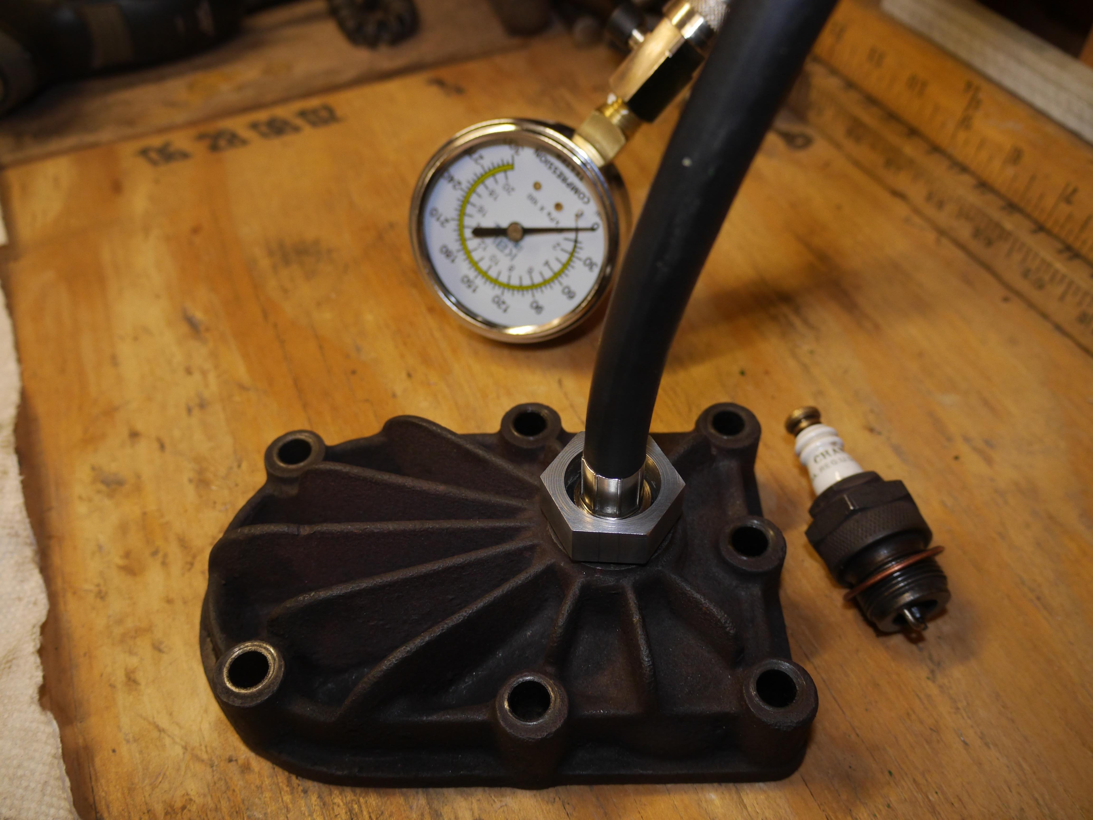
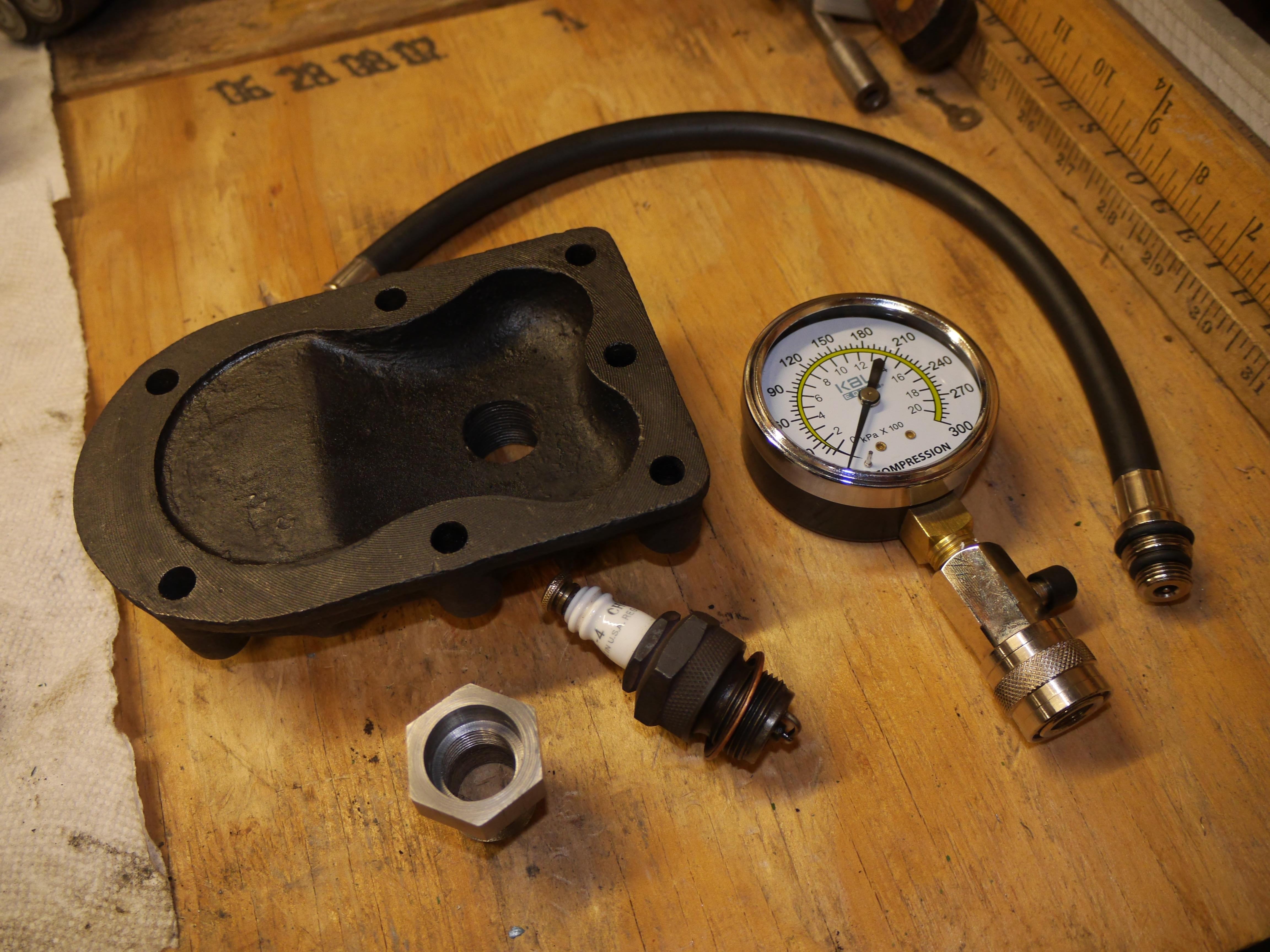
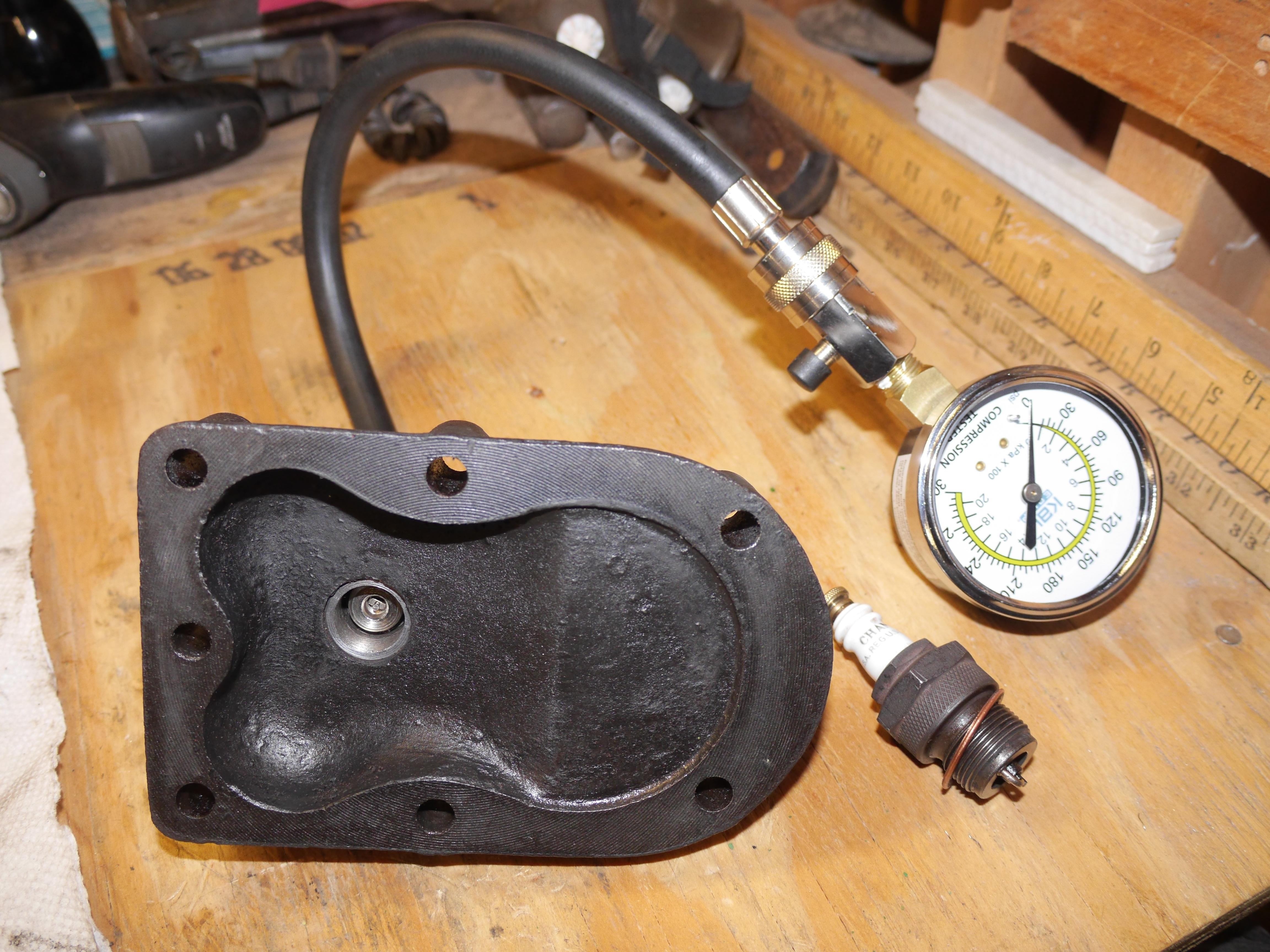
Now that every part has been meticulously cleaned, I took some time to machine a compression gauge adapter for the 7/8” sparkplug that this engine uses. I faced and center drilled a piece of 1-1/8” hex stock so that I could drill the 21/32” hole to accept the 18mm x 1.5 spark plug thread. I turned the opposite end of the adapter down to 0.875” and set my lathe up to cut the required threads in the adapter. The threads came out great, and now I have a 7/8” sparkplug adapter for my compression gauge…….or at least I thought I did. I did not like how far into the adapter the Schrader valve in the compression tube sat, so I set up my boring bar and bored a seat 3/8” down from the face of the adapter. I turned a few more internal threads and I had an adapter I could be proud of. Why all of this effort???, Well I am a bit of a nut. I have a tremendous amount of details on all of my three hundred plus engines, and this could not be the only engine I did not have a compression reading on. As a side note, if you look at the underside of the cylinder head, Coldwell turned the mating face of the head on a lathe. I know this is true because the head on my other Coldwell is machined the same way. I guess it gives the head a better bite on the head gasket.
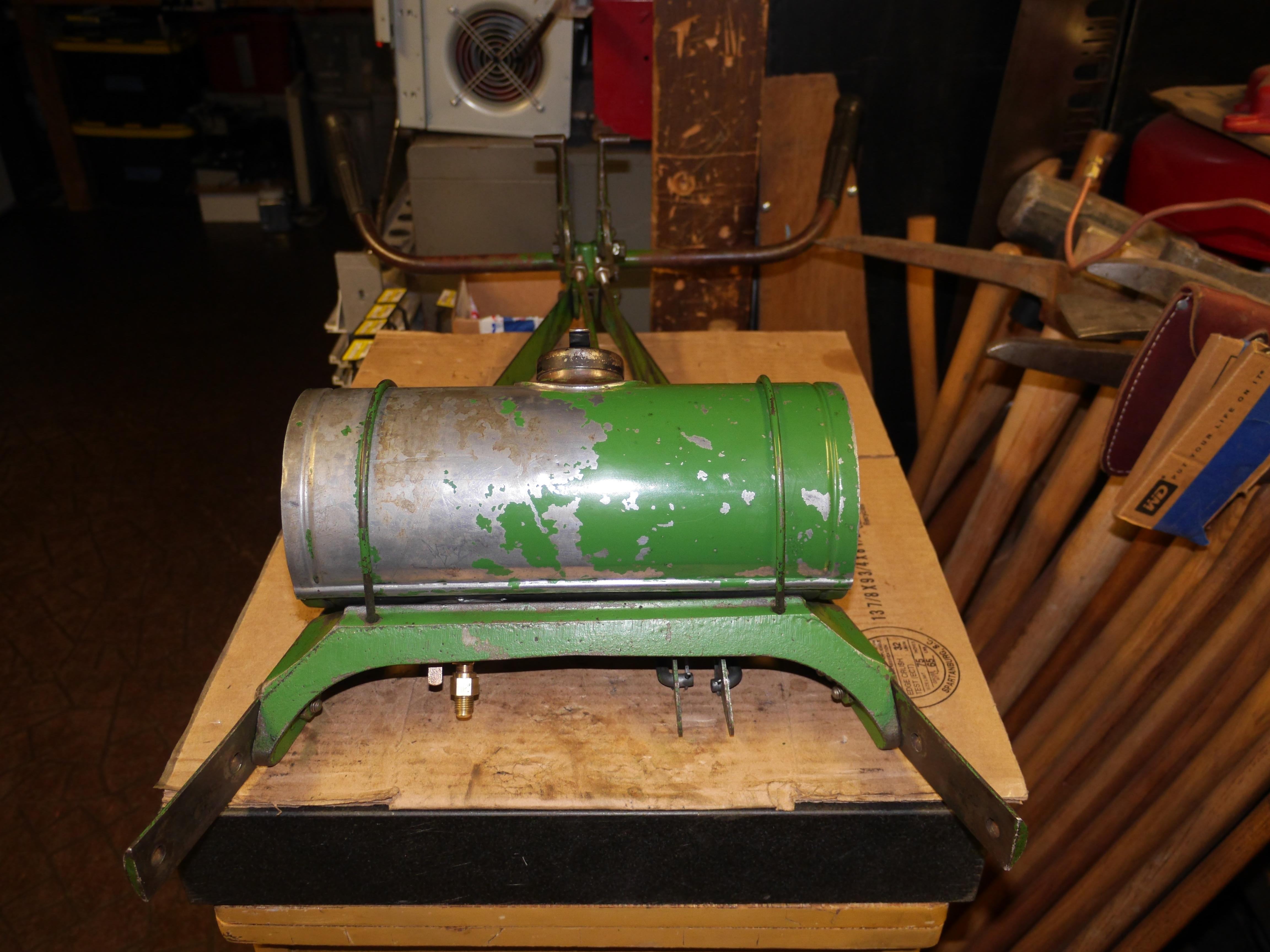
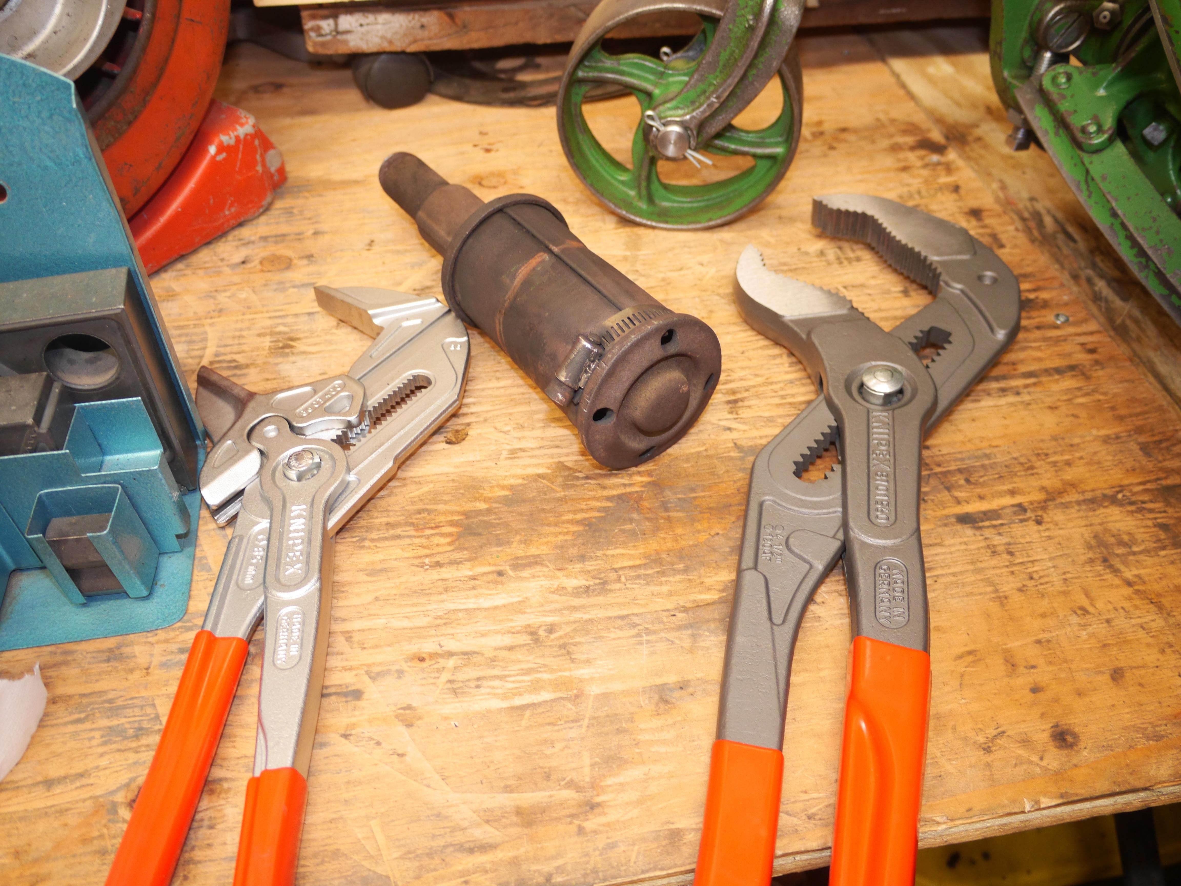
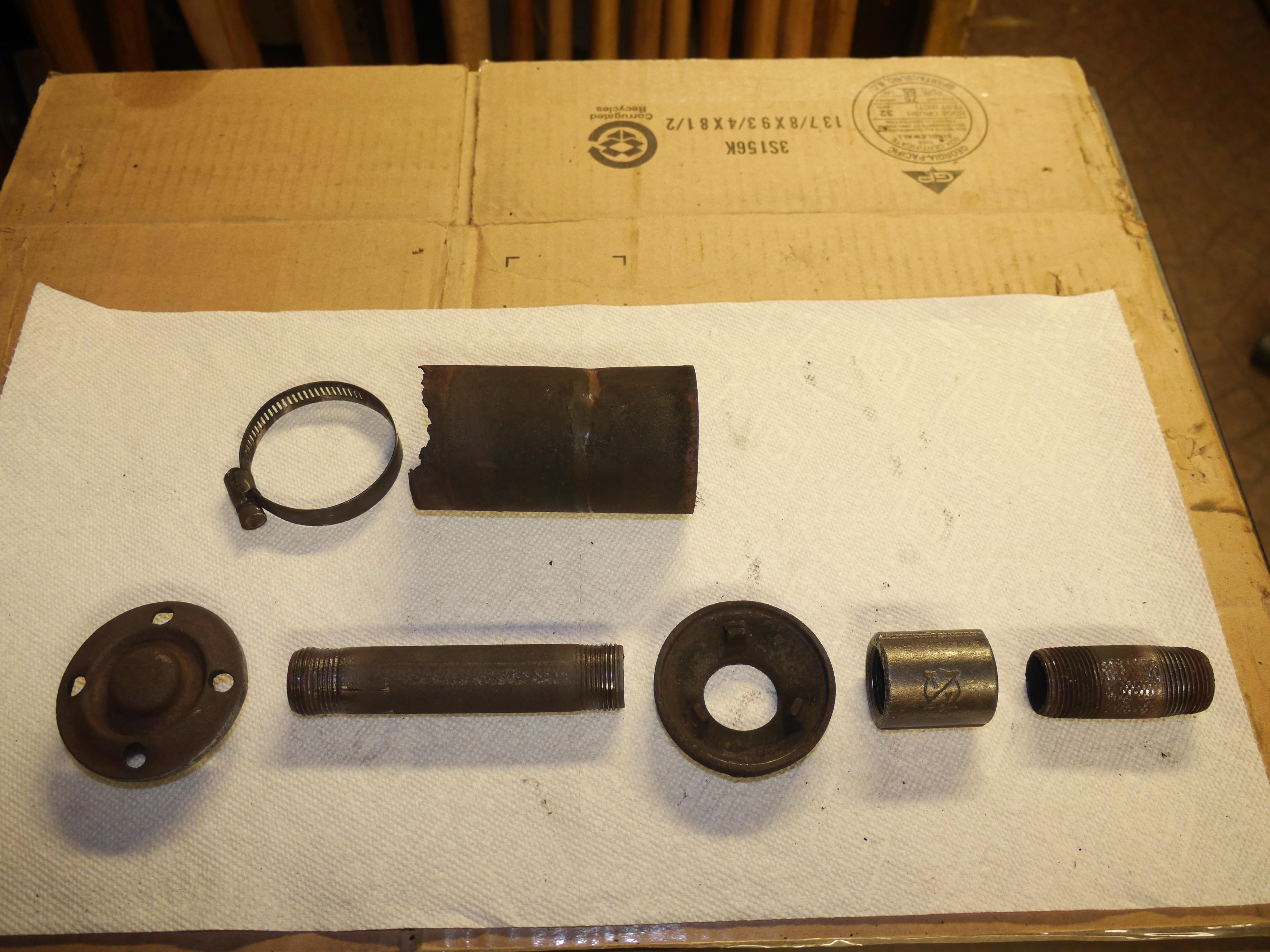
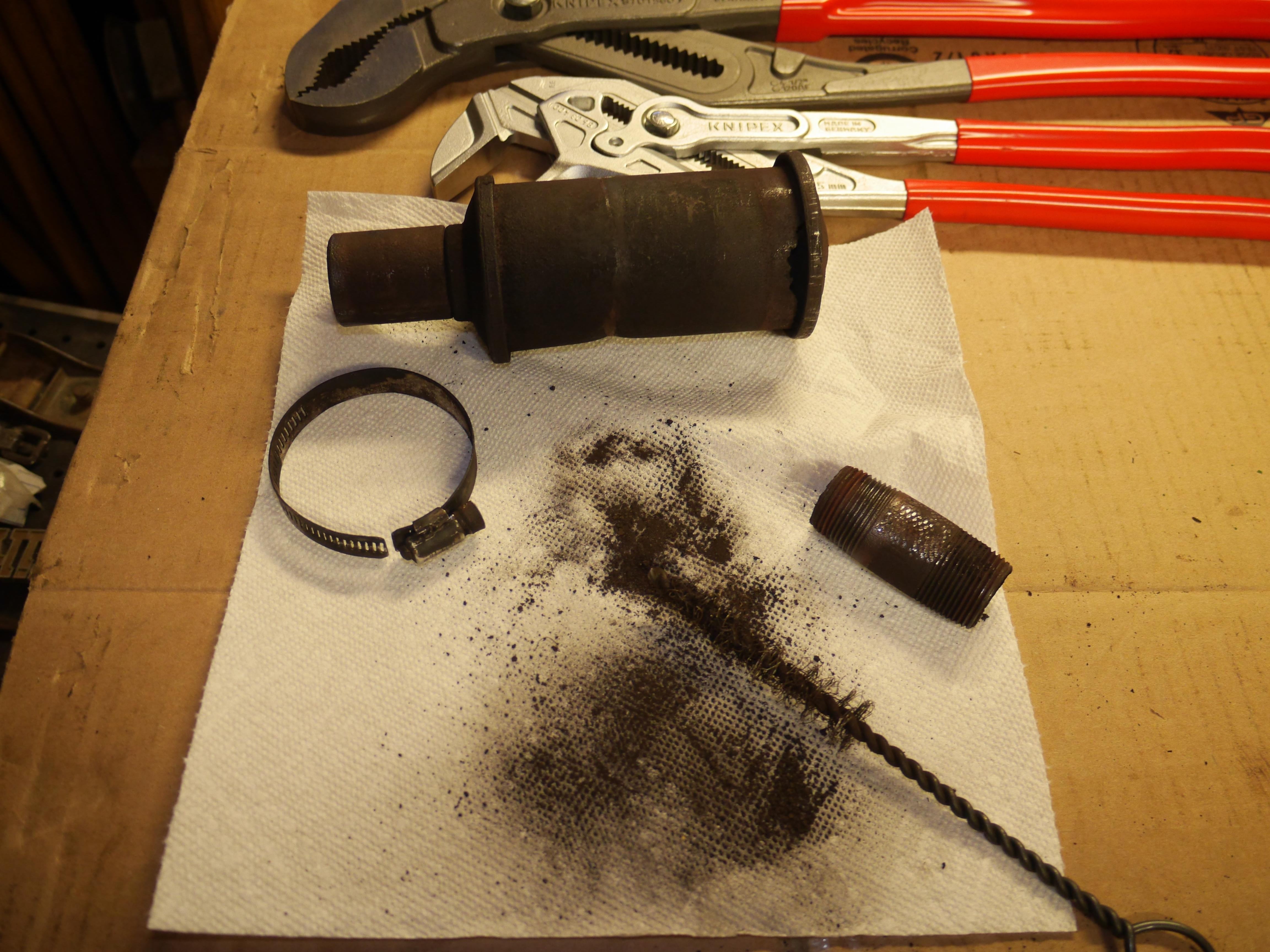
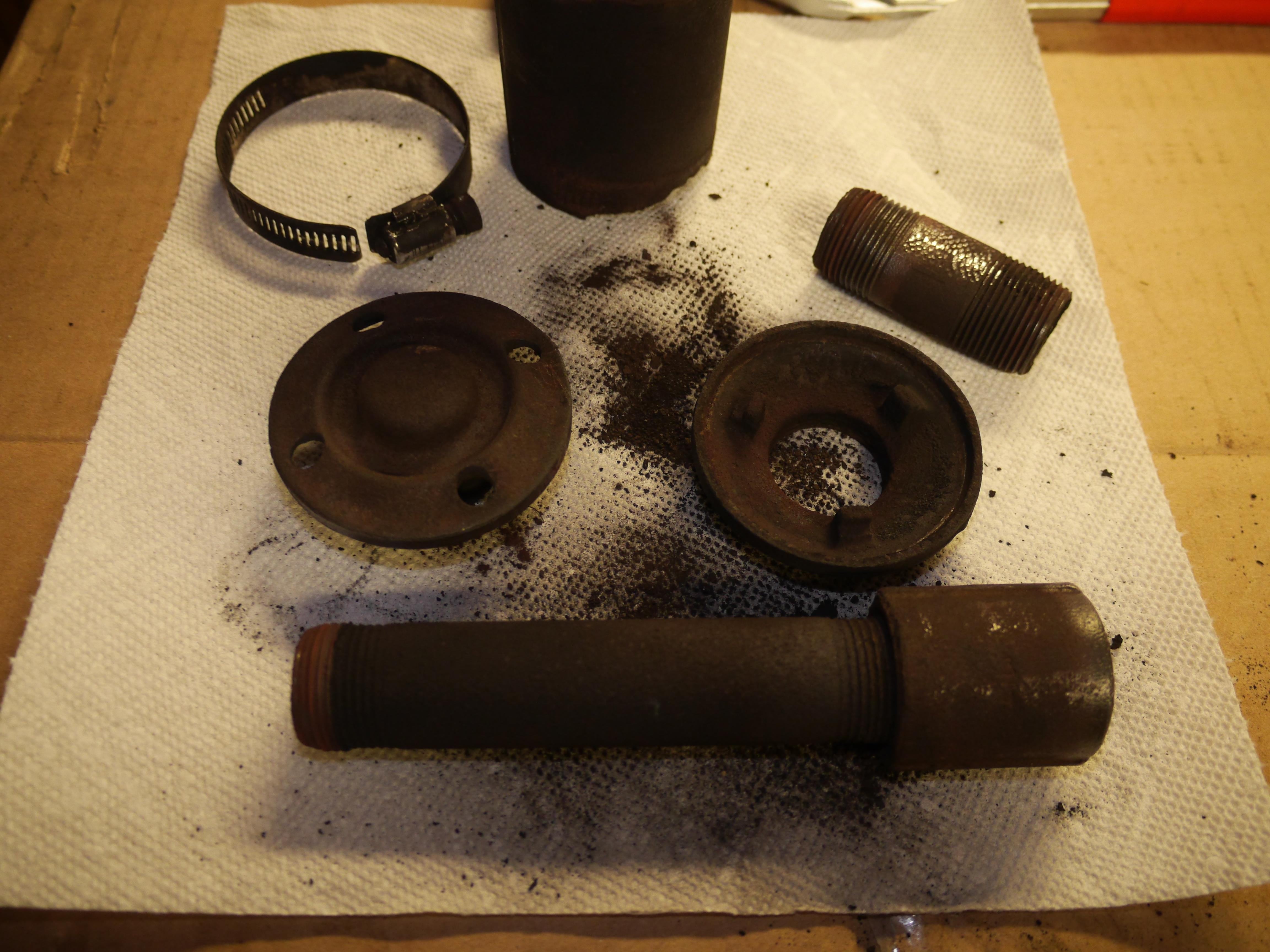
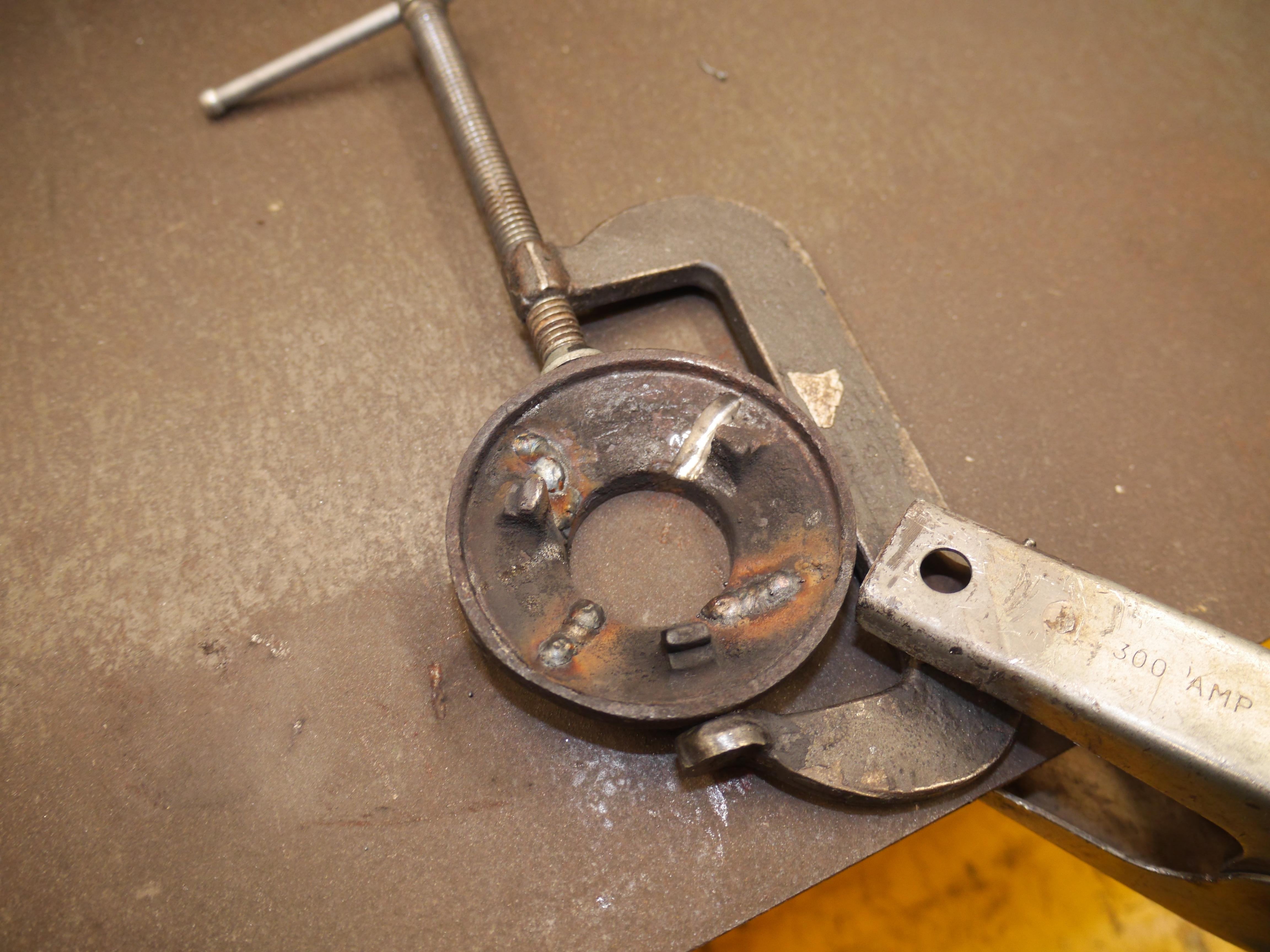
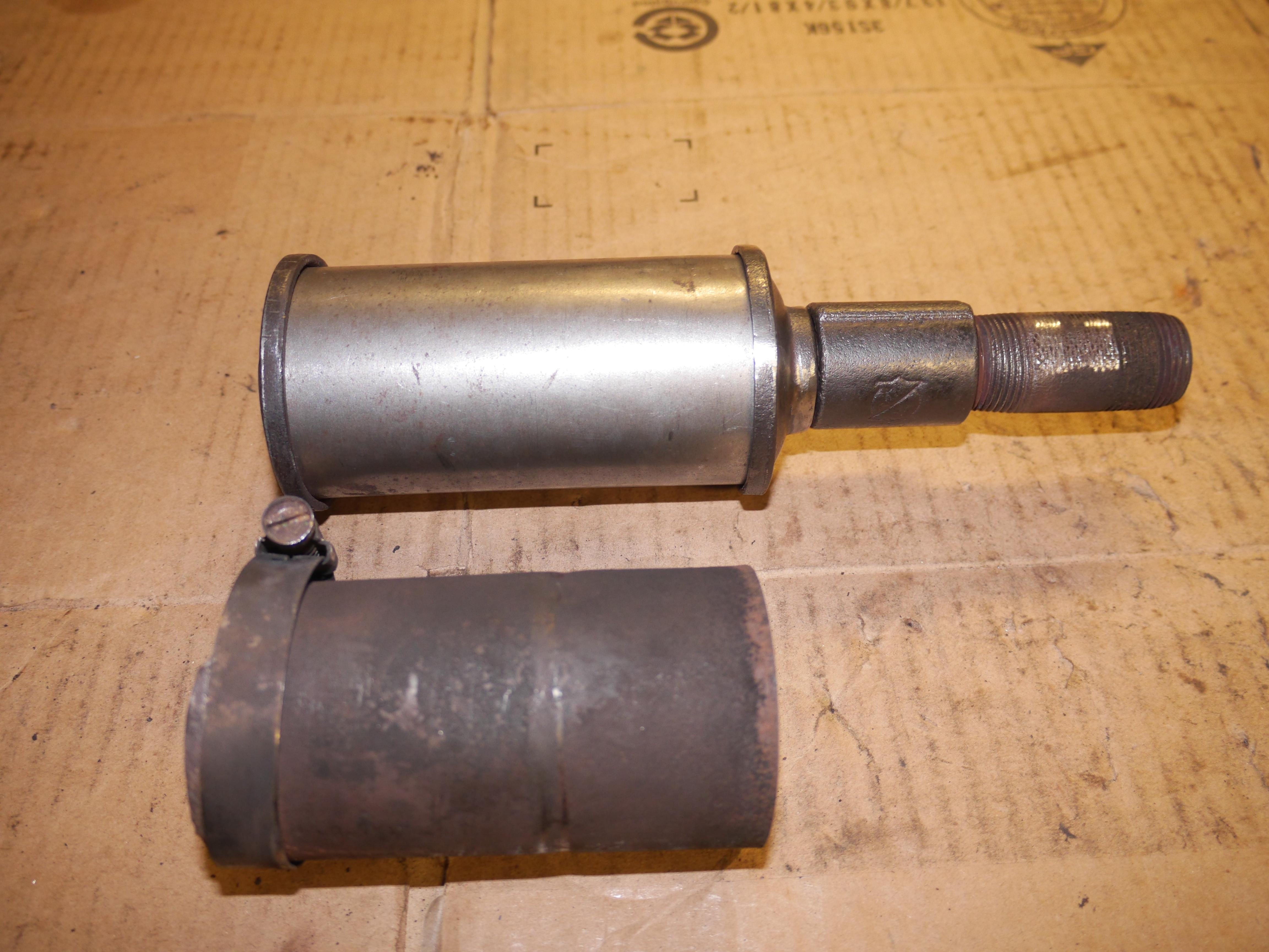
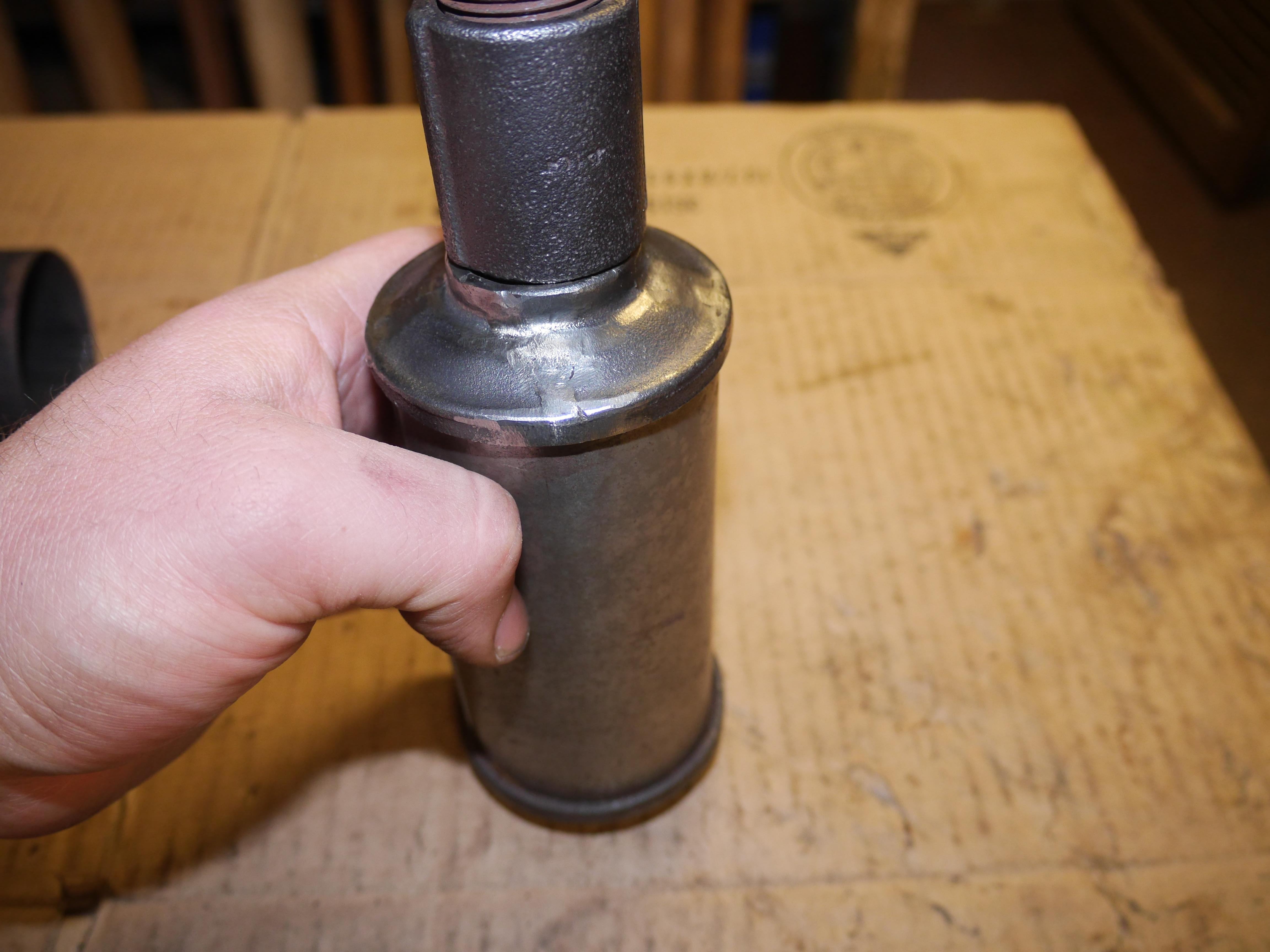
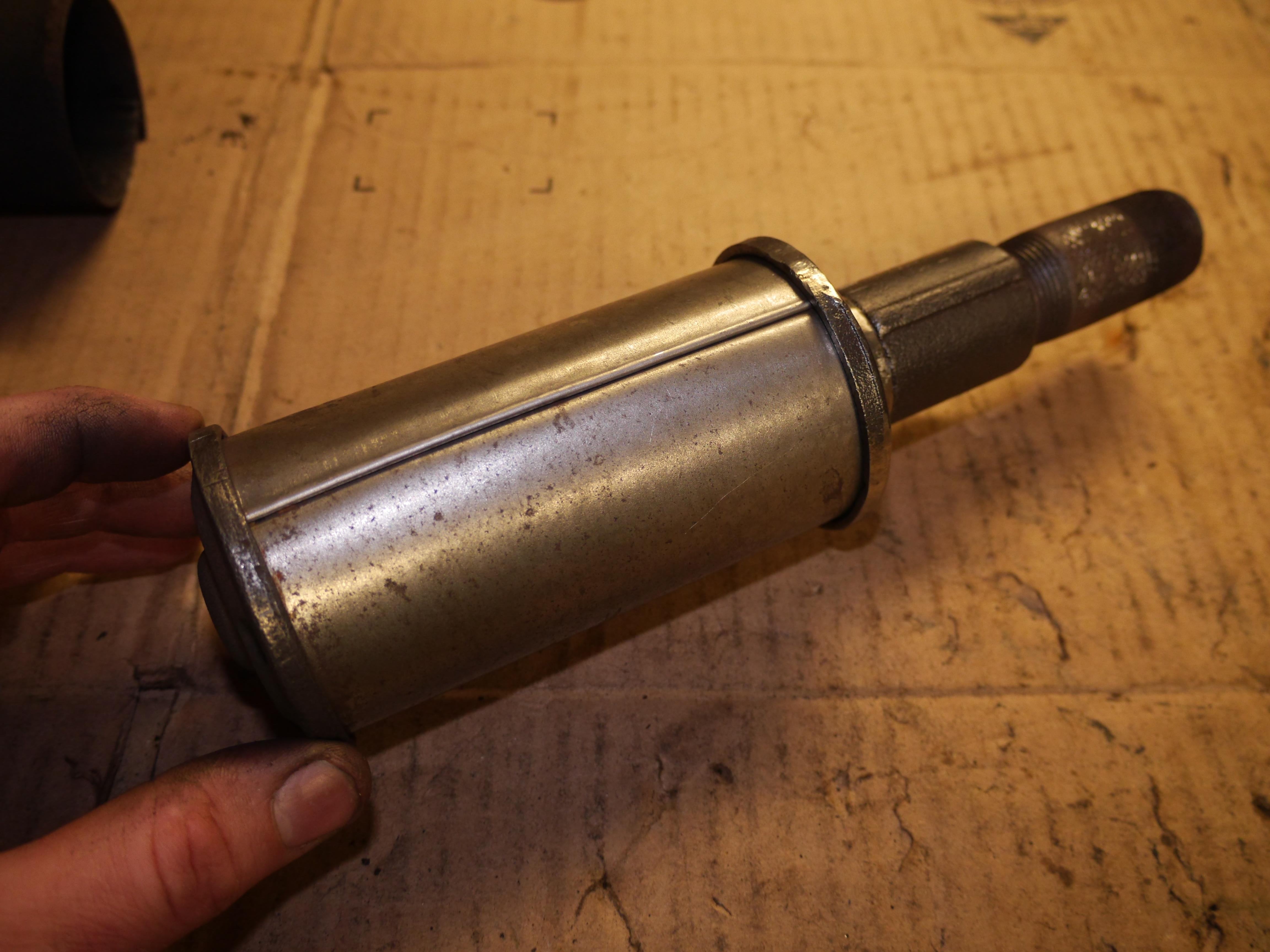
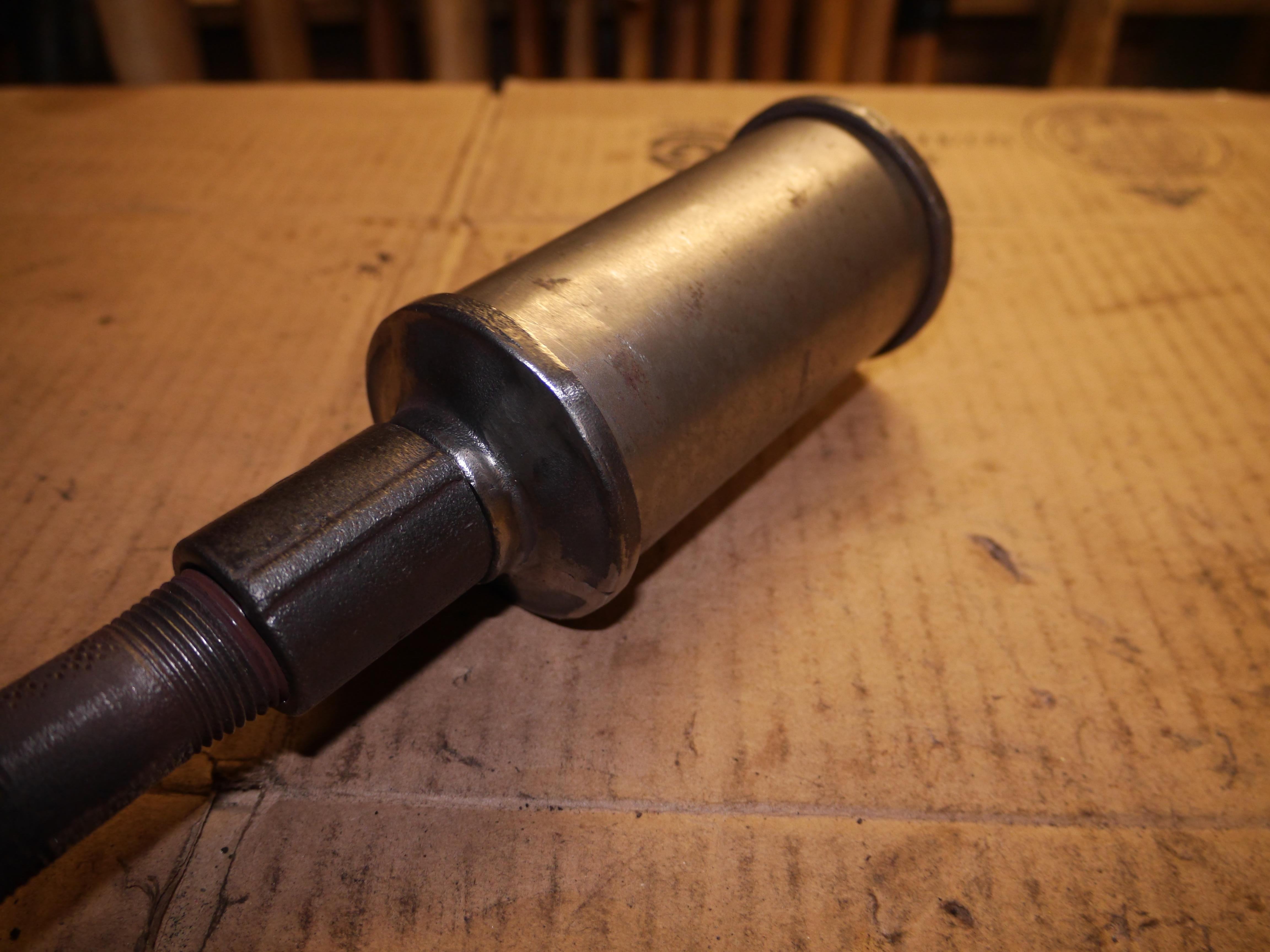
Next I decided to do something about the ring clamp holding the muffler together. With my extra large Knipex plier wrench and cobra pliers I was able to remove the seized in place muffler without damaging anything. In order to separate the muffler from the pipe nipple I decided that it would be best if I sacrifice the pipe nipple to save the specialty pipe coupler. This allowed me to really clean up the reverse of the muffler threads really good. With my smooth jaw plier wrench and a smooth jaw vise I was able to separate the muffler without damaging or marring anything special. The construction of this muffler is quite intriguing, and I will be replacing the two worn out pipe nipples. The rusted through can of the muffler just had to go. I took some measurements and was actually ready to machine a new can out of some 2-1/2” o.d. solid round stock before realizing how out of place that would look. I sat down and came up with a game plan on how to recreate the muffler can, and I think I nailed it. The new can looks just perfect. I assembled the new can into the cast iron head of the muffler and then aligned the rear cast iron cap of the muffler. I was two seconds from finishing the job when I heard ‘ting’ and the rear cap shattered into four pieces on the ground. I was so upset.

Without a good way to clamp the broken cap together I hot glued as much of it together that I could. Once the glue set I gently clamped the outside of the cap so that I could run my carbide burr over one crack at a time. I had no choice but to weld the cast cap cold so that the glue would not melt. The beauty of hot glue is that it peels right off in one piece if you can catch it before it re-melts. One crack at a time I welded the cap back together. Once cool, I re-ground the cap with my carbide burr and welded up both sides. It actually came out surprisingly nice considering that this was dirty cast iron completely impregnated with carbon. I have full intentions of having a new cap re-cast, as this is easily a six hour job to machine a new cap from scratch on the equipment I have. For now it will do. I still have quite a few odds and ends to finish up on this mower before it is ready to be put into service again. Until next time, I hope you have enjoyed the adventure in bringing this 1931 Coldwell back from the dead.
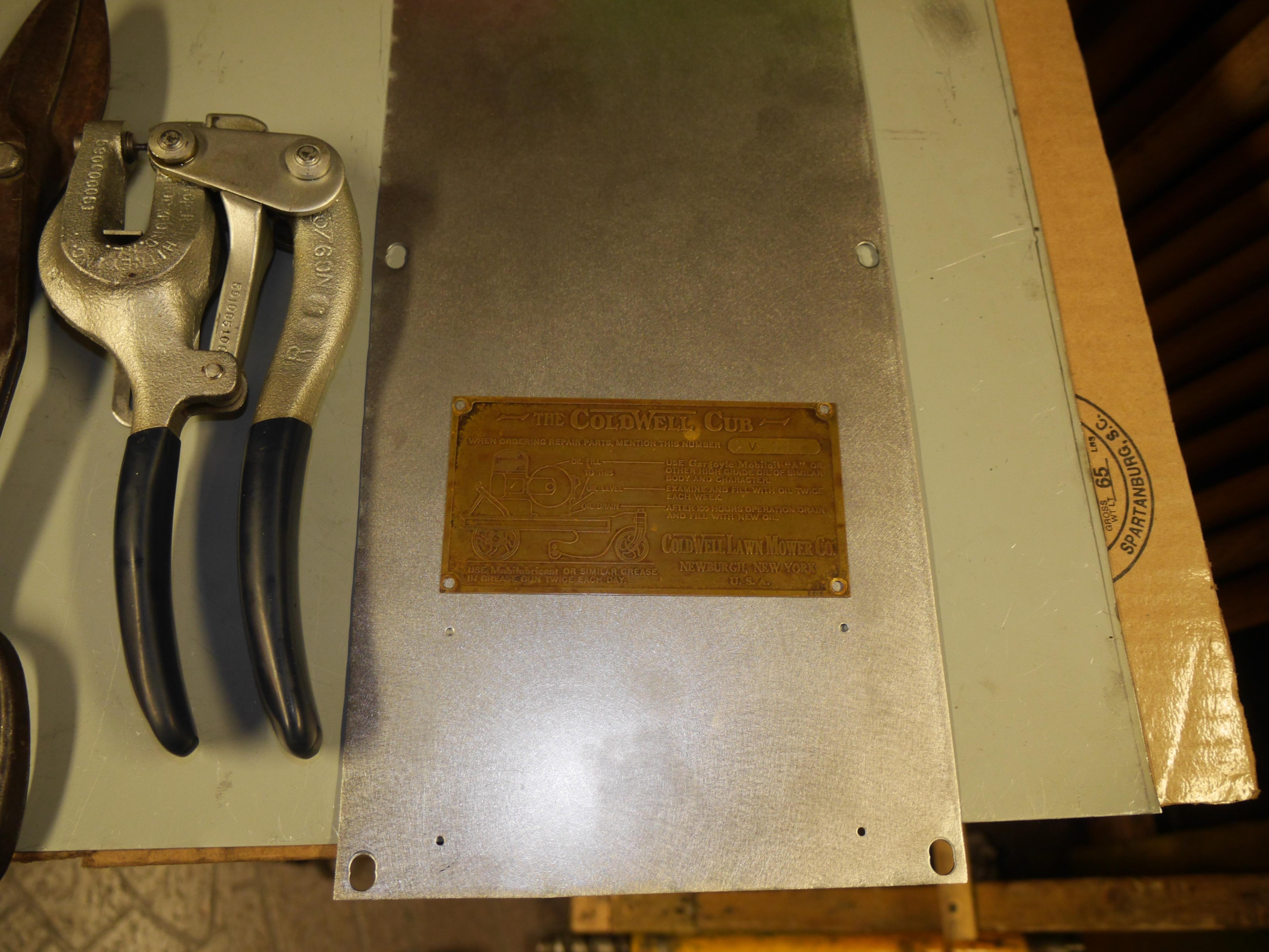
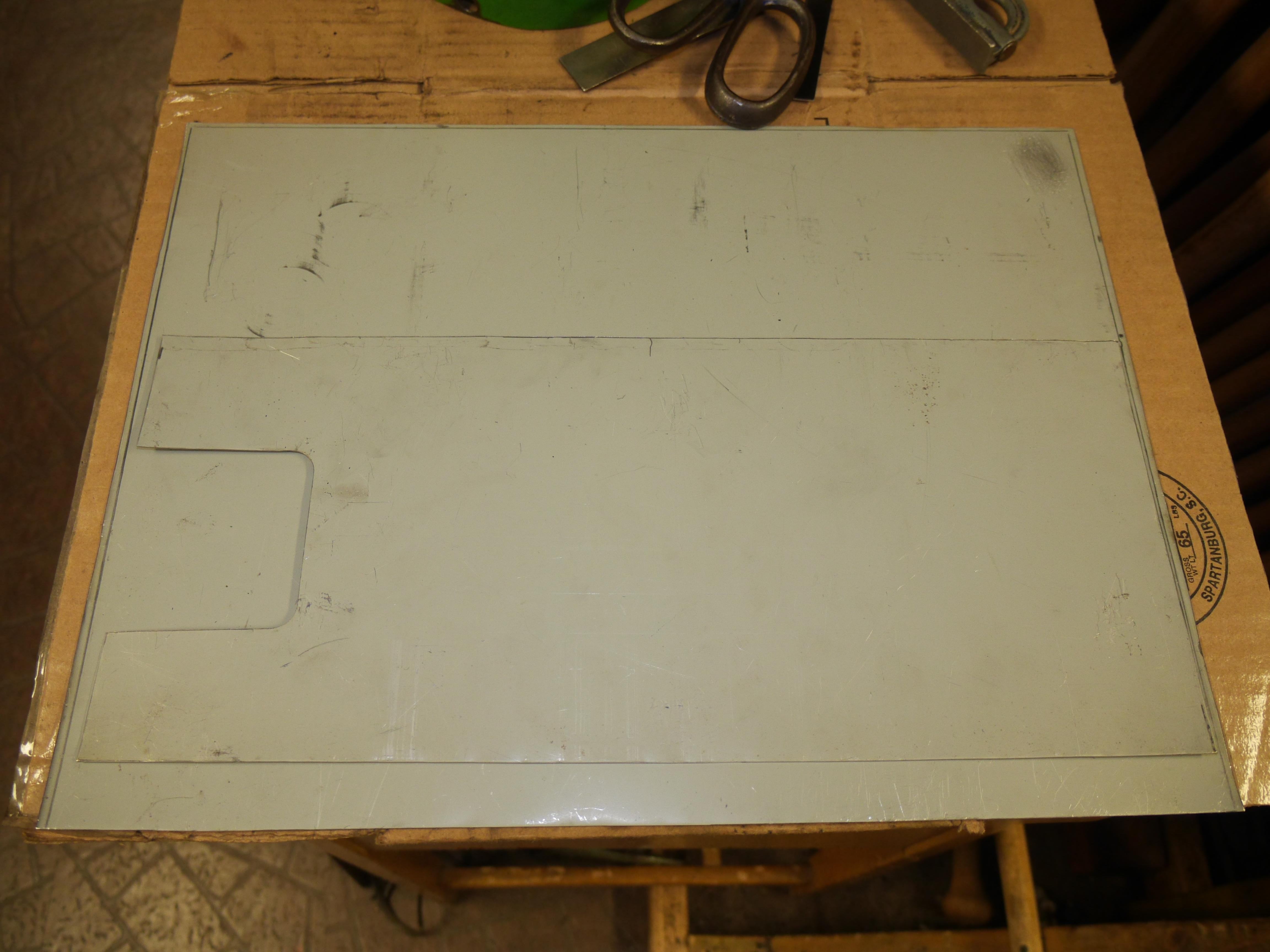
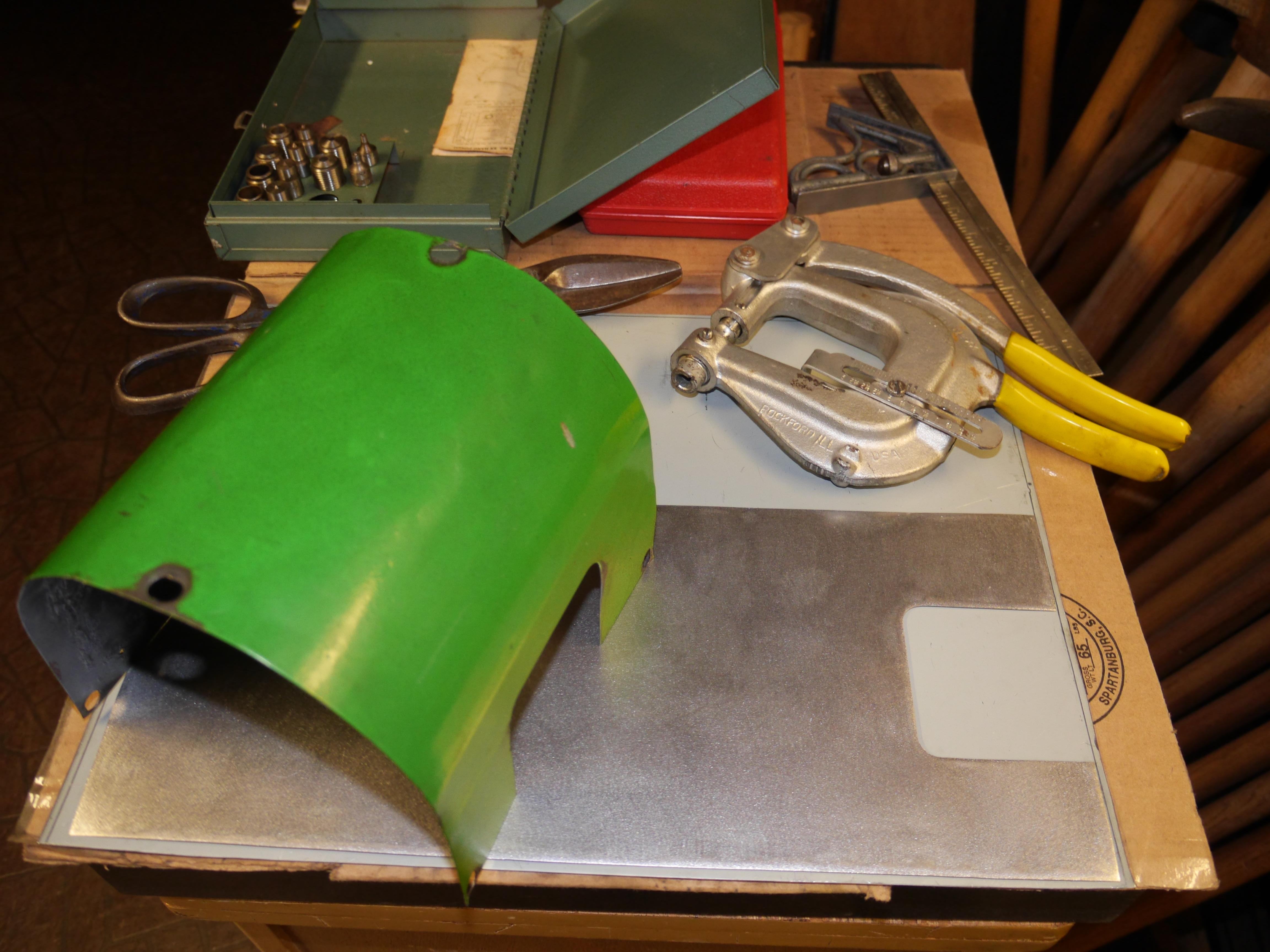
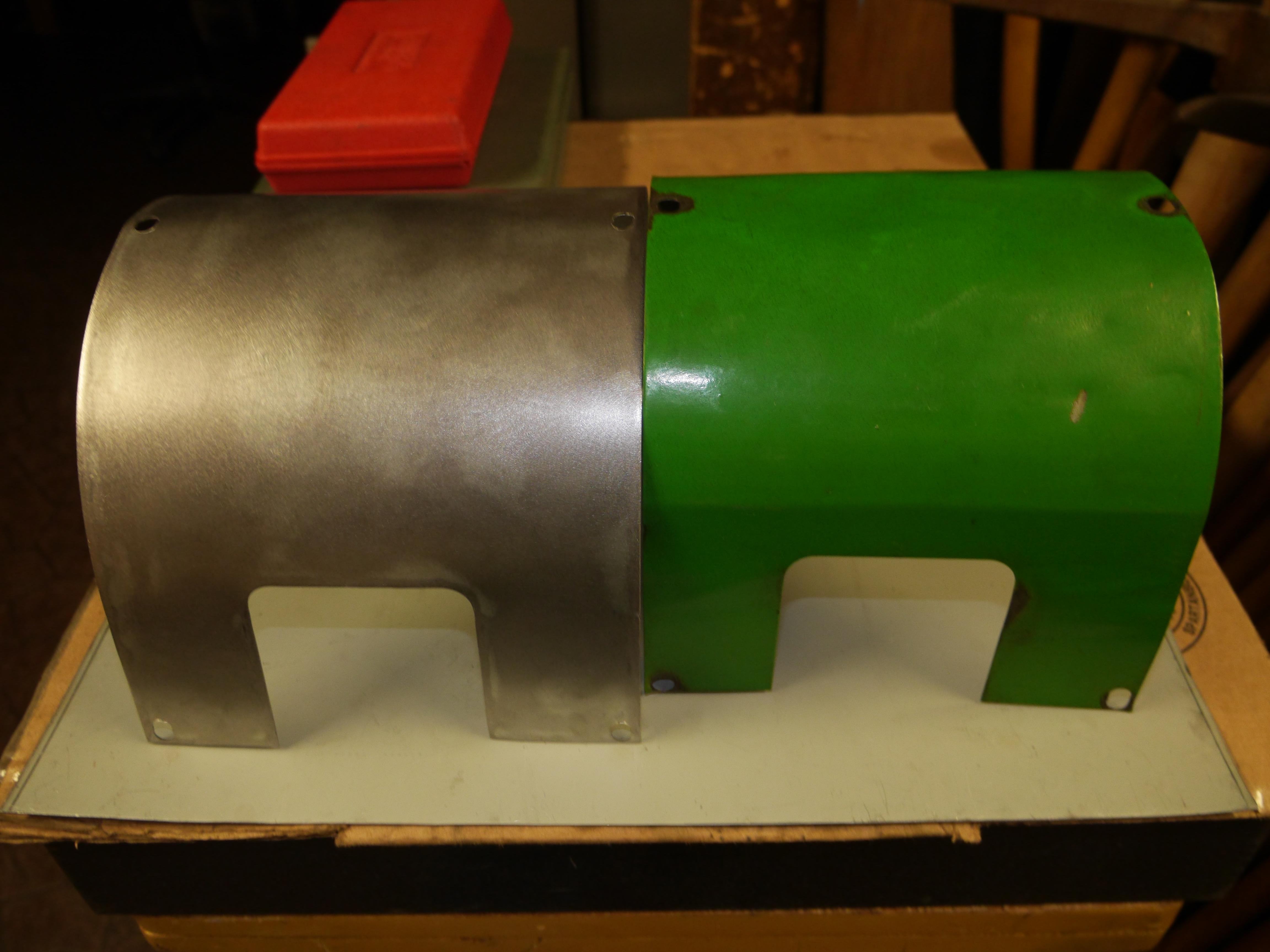
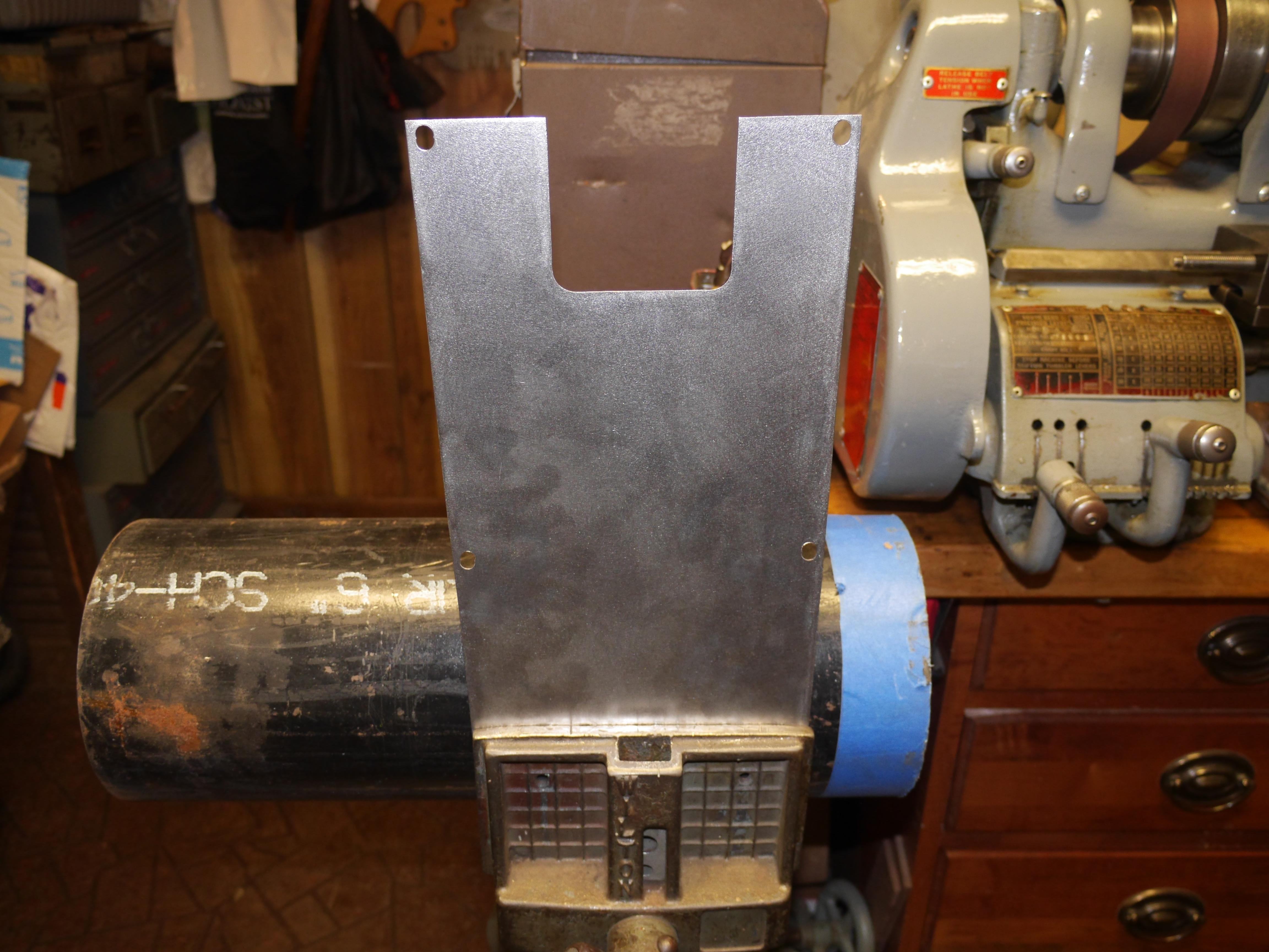
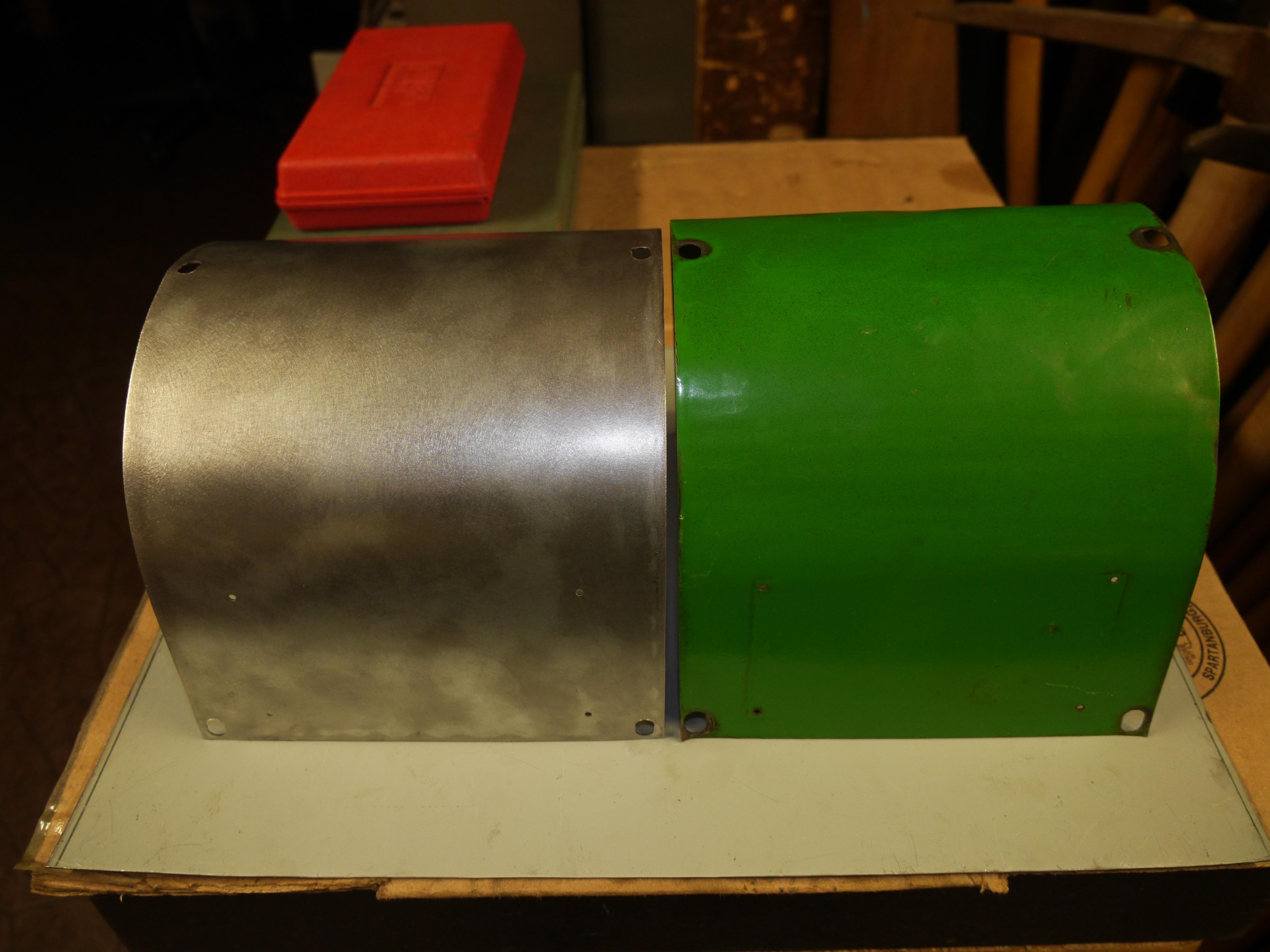
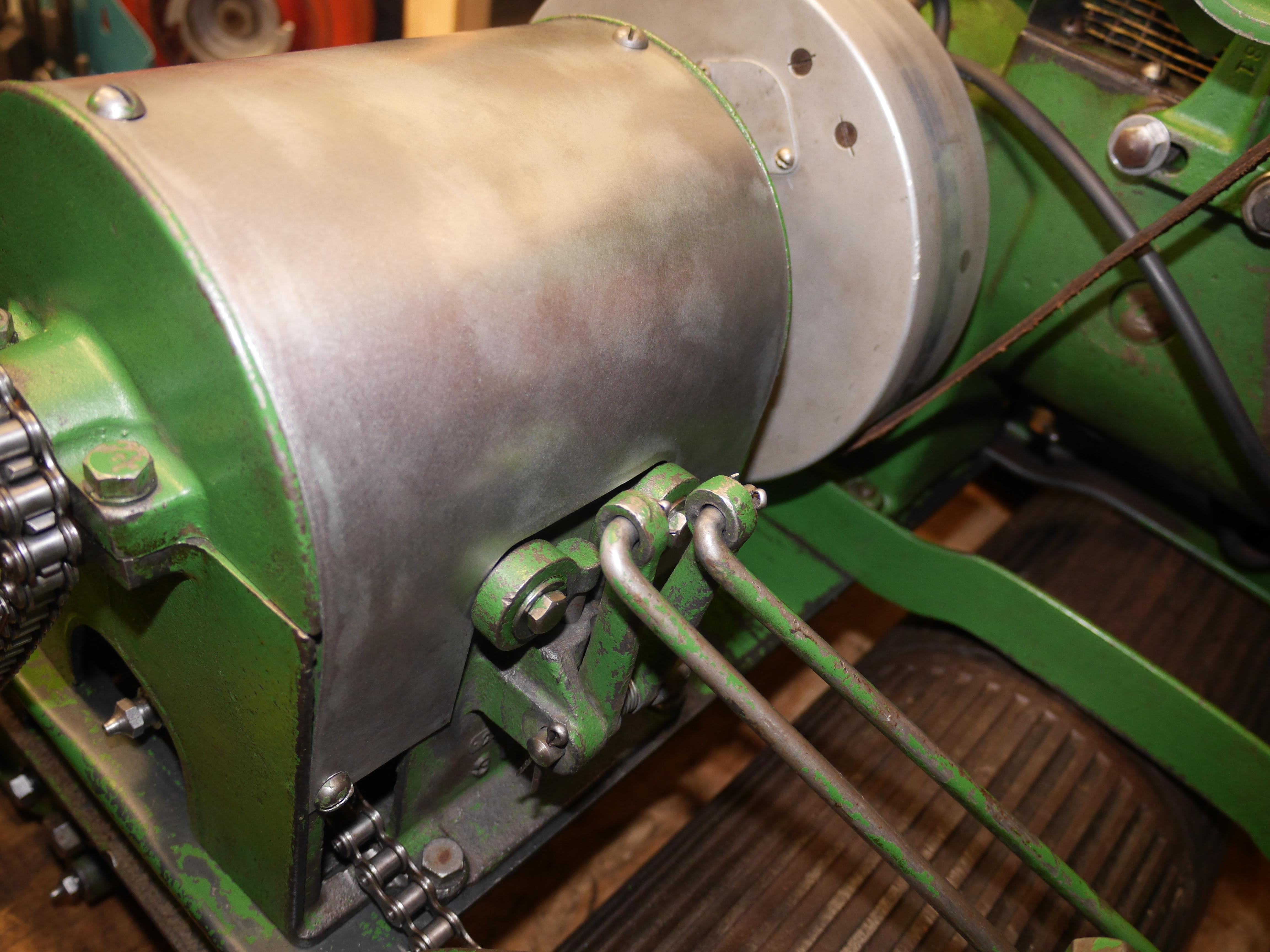
I dug out my 1935 Coldwell Cub this afternoon so that I could make a duplicate transmission cover for my 1931 Cub. As always the 1935 starts on the first pull and runs just perfect every time. It might be the most reliable engine I own. Even my prized Wisconsin's do not start as easy as that old girl. I dug through my sheet metal scraps and I had the perfect piece of steel just a few days ago before I cut it up to make the muffler can. I continued to look around and I stumbled across a really nice piece of 0.040" sheet metal from a mid 1990s Pentium 3 server case that I had kept around for too long. The side panel finally had a fitting use. I cut out the 7" x 16-1/4" piece that I needed, and then sanded it all down to remove the black painted finish. A few minutes with my Roper Whitney hand punches and I had a perfect blank to bend into the transmission cover. It turns out that the contour of the original transmission cover matched the outer curve of a piece of 6" black iron pipe. It took a little finesse, but the new transmission cover is an exact duplicate of the original. It fits just perfect, I could not be happier. The next update will probably be in a weeks time. I need to order some steel and supplies so that I can machine the remaining various oversized and custom fasteners that are either missing or mismatched. The only thing I have not been able to find that I cannot machine are three 1/8" NPT Alemite Zerks to match the rest of the grease fittings.


Thanks for Reading!
Want more? Here's a behind the scenes look at my workspace and some of the images that did not make the cut to be included in the write-up: