Remanufacturing a Missing Antique Chainsaw Clutch Cover

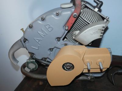
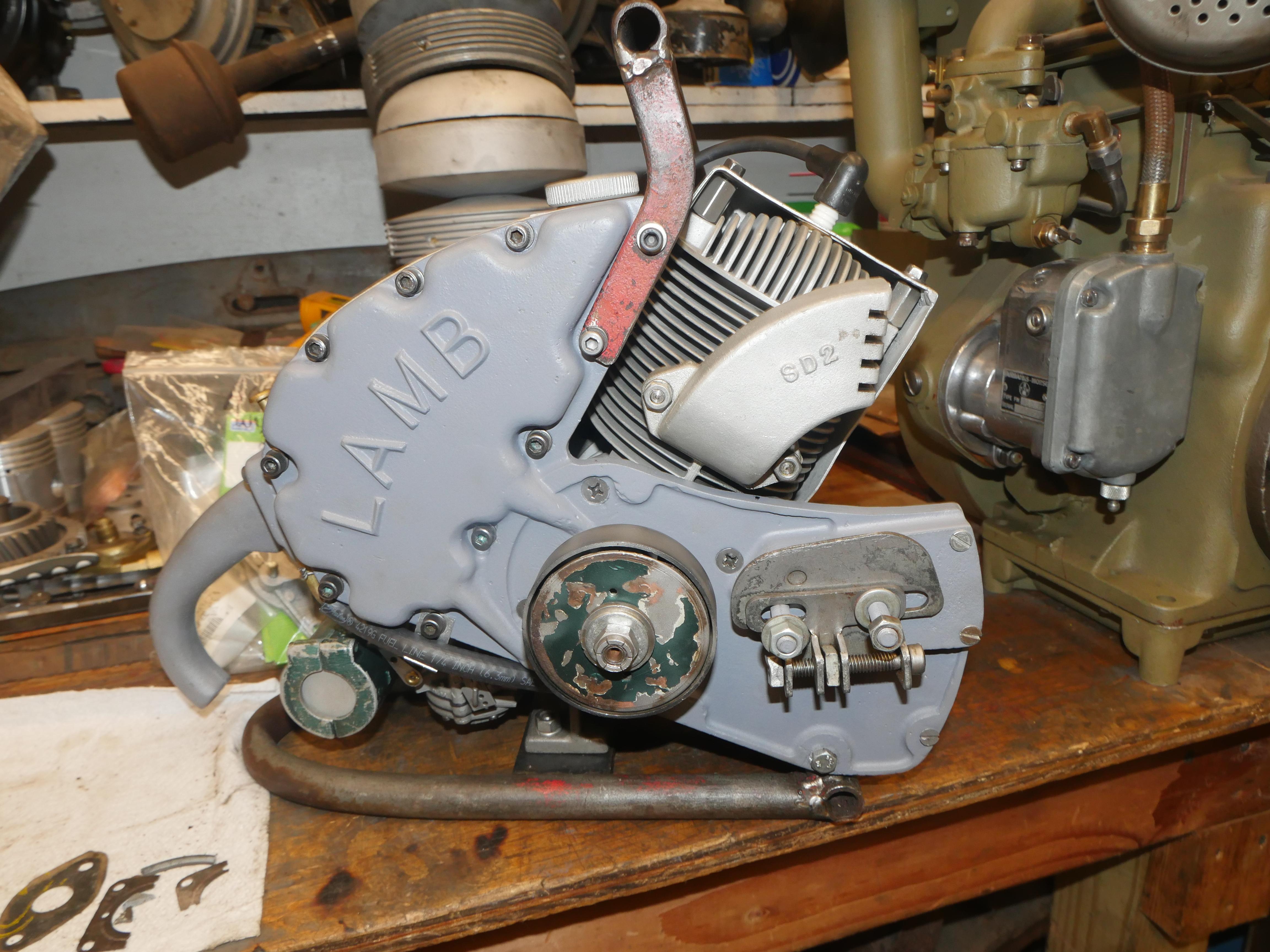
I bought this 1958 AC Lamb chainsaw made in Liverpool New York in June of 2021, which I thoroughly disassembled in December of 2022 when I brought it home. It was in really bad shape, thoroughly corroded and full of mud. It took many months to track down some very hard to find engine parts to bring her back to her former glory. From February thru March of 2023 I rebuilt the engine with all new bearings, rings, snap rings, gaskets, seals, etc. The engine is now brand new and runs perfectly.
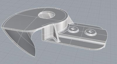
Sadly one critical part was missing, the clutch cover. This cover houses the tensioner for the bar and chain, so it is necessary for operation of the saw. Since I did not have one, I sought out another example of this saw, owned by Dean Depew of Sherburne NY. Dean let me take lots of pictures and dimensions of the clutch cover on his saw so that I could begin the process of making one for my saw. I consider this to be a rare saw with less than thirty known examples left in existence, so a valiant effort must be made to bring it back to its former glory.
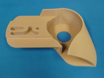
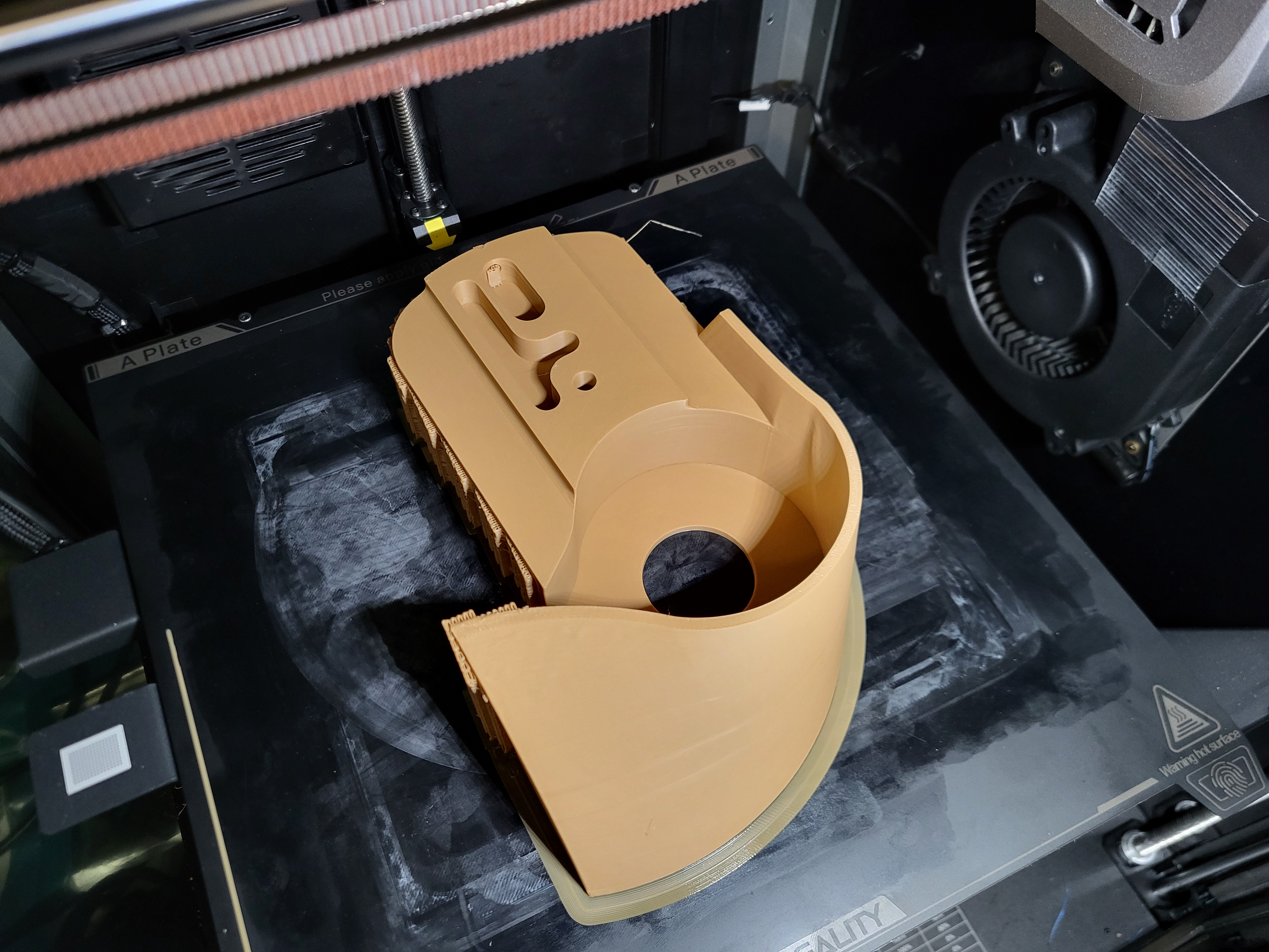
Last weekend I drew this part in Rhinocerous, often abbreviated "Rhino," a 3D modelling software for architects. There is nothing simple about the geometry of this clutch cover. Everything is curved and contoured to fit snug around the clutch and the engine.
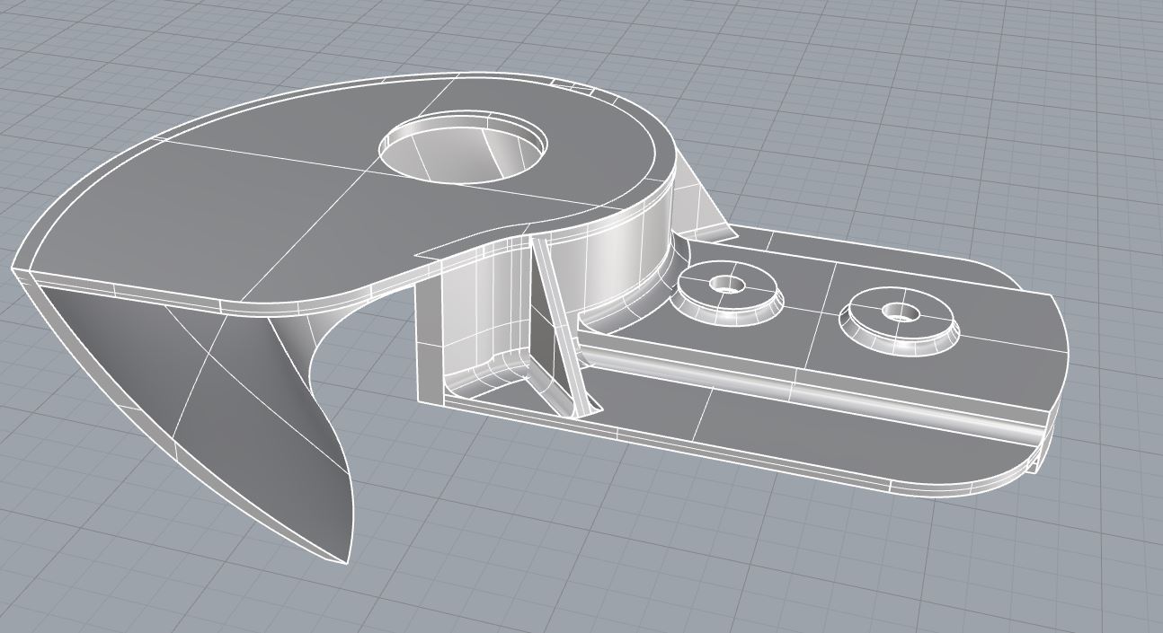
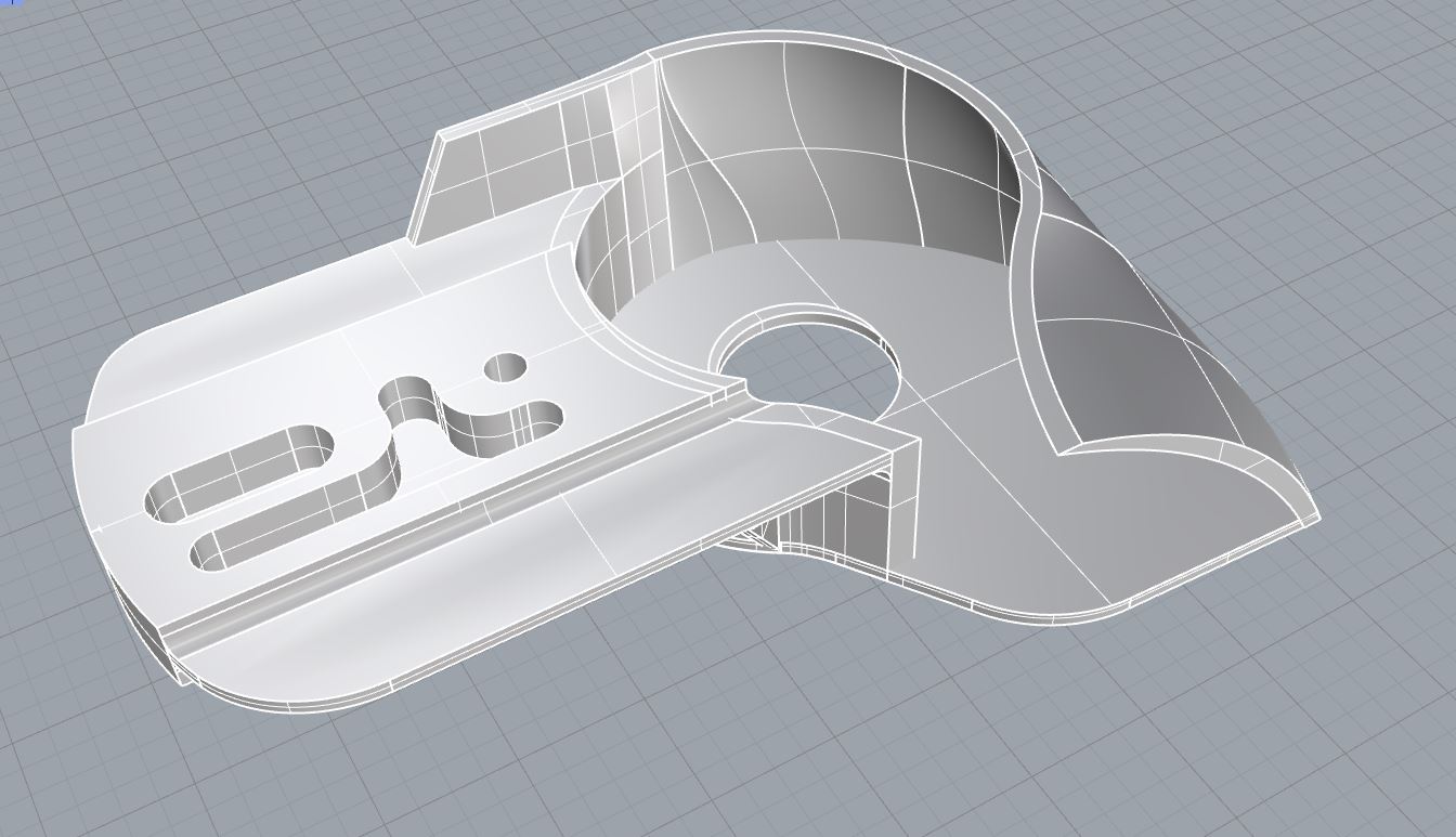
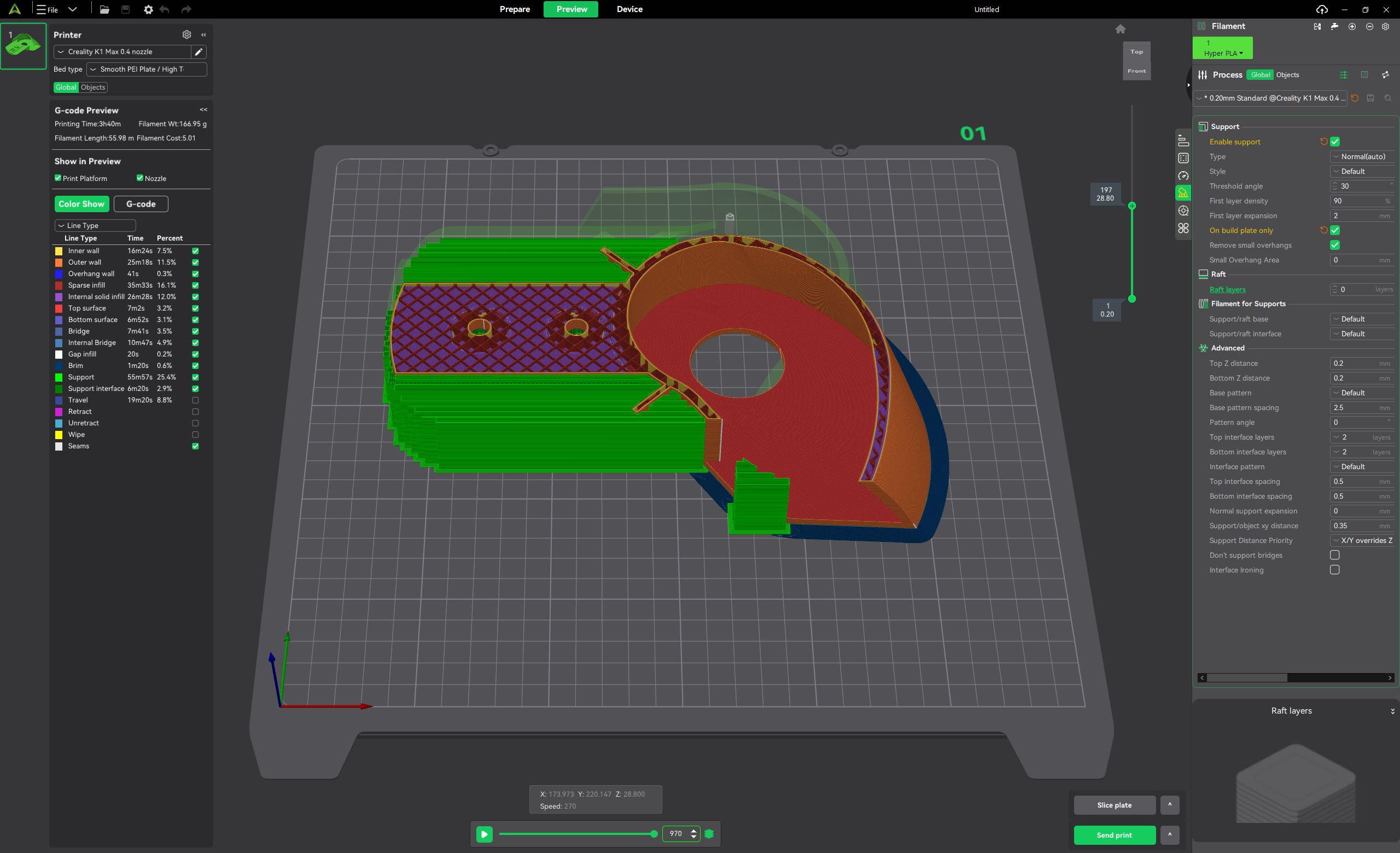
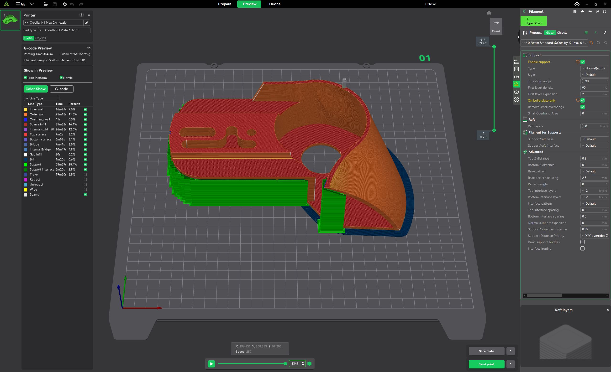
Rhino is not really a solid modeling parametric program like NX, solidworks, onshape, ptc creo, etc.. but with some tricks you can force Rhino into making closed surfaces and solid bodies. After several dozen ___ sweeps, and a final surface union function, I was able to export a usable .step file, which is a relatively universal file format for solid modeling. Luckily, recent advancements in 3D slicers brought direct .step import capability directly to slicers like PrusaSlicer, OrcaSlicer and Creality Print. .step files offer more detailed part information than .stl and is frankly more convienant to work with since you are no longer dealing with a point cloud.
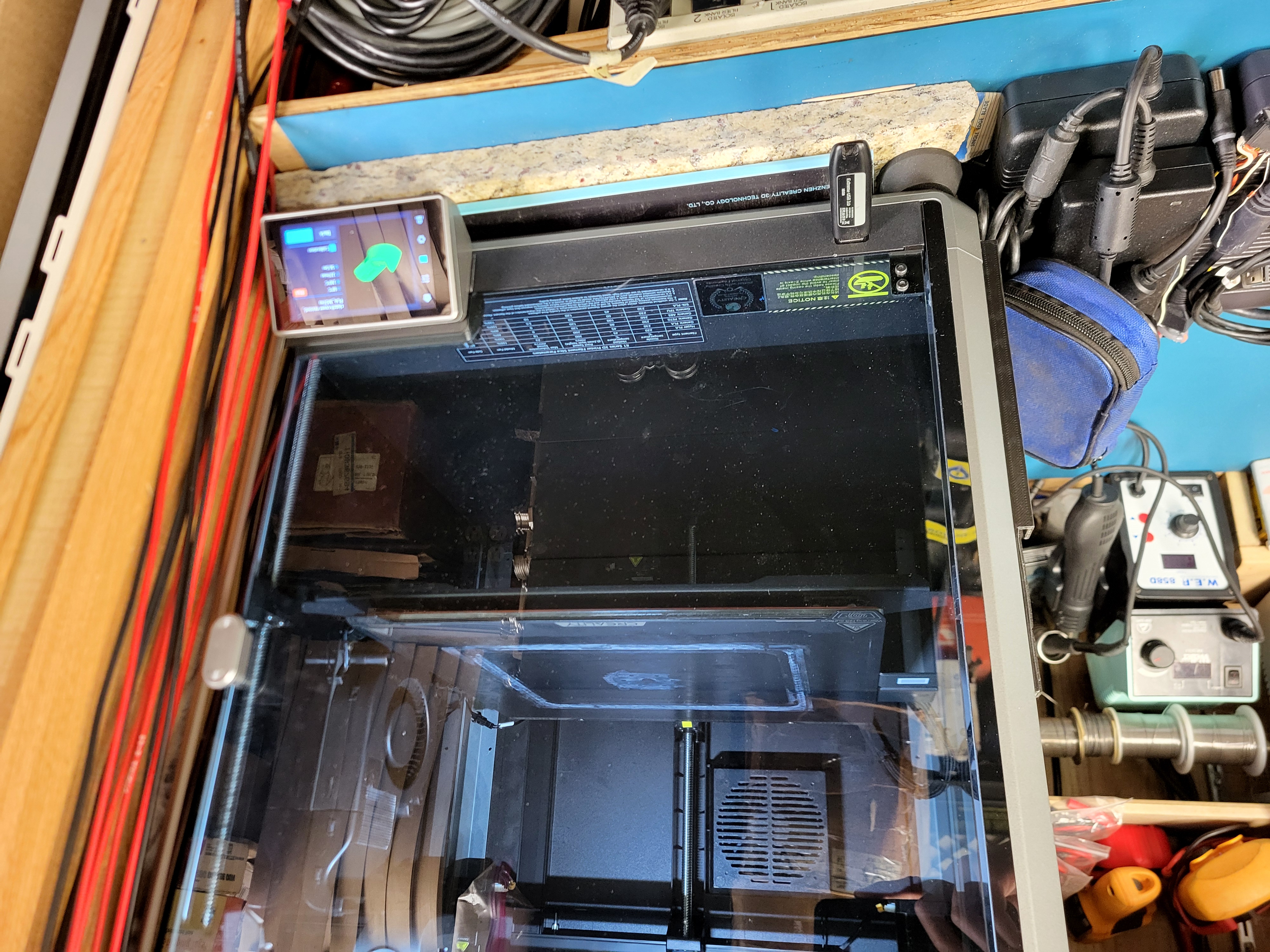
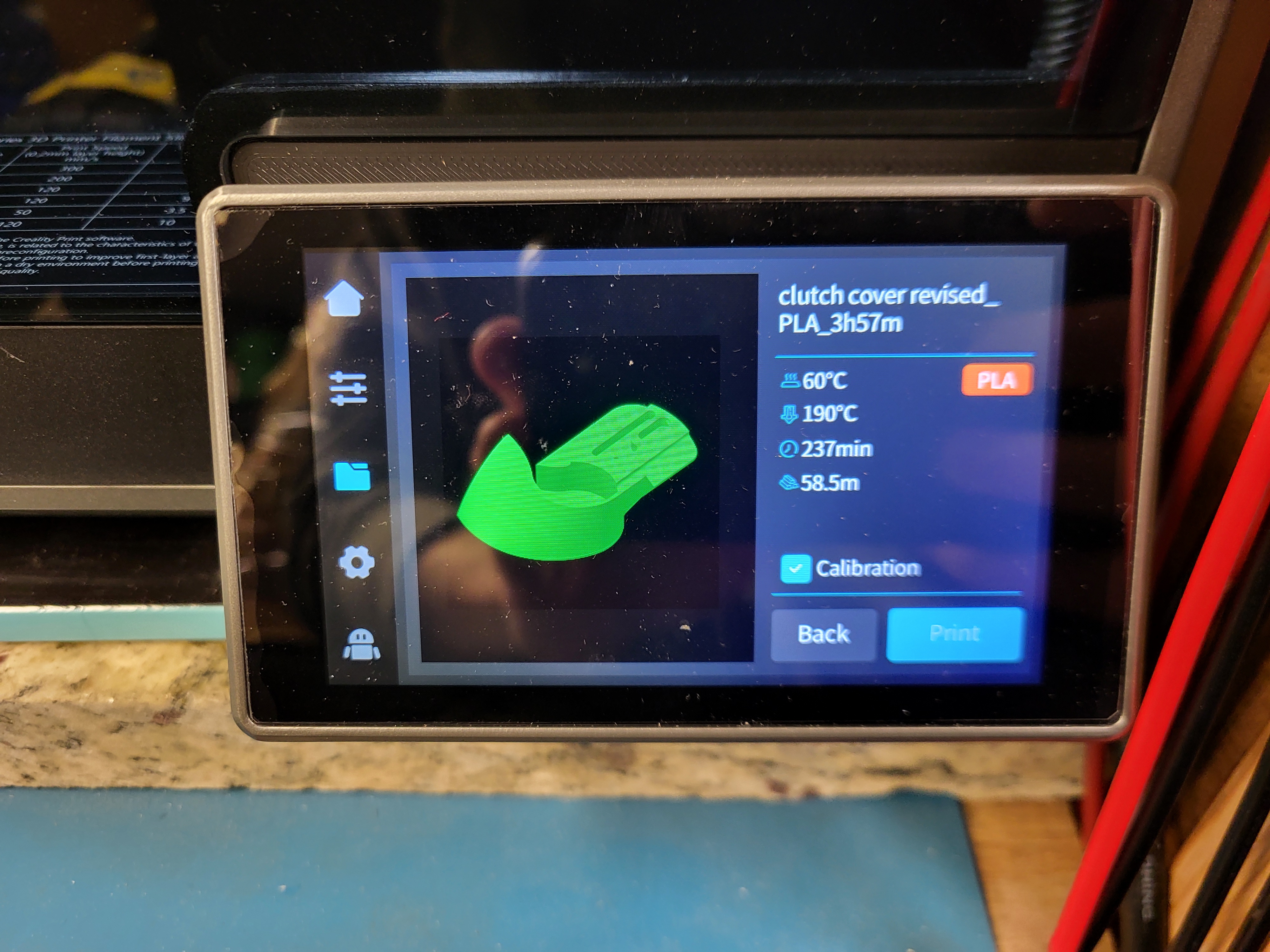
My brother recently picked up a Creality K1 Max 3D Filiment printer and it has been a real treat to use for modeling small parts under 12in cubed. In the essence of time, I stuck with Creality Print for this job since it had a built-in profile for the printer. With some minor tweaks, it worked surprisingly well for this new part. Just several months back, Creality print could not integrate circles correctly and would often create ovals instead of circles. Yes, I checked my belt tension, bed leveling and ran input shaping, but what solved that problem was just switching to prusaslicer for the time being. It seems the creality developers fixed the problem since.
This part was printed in PLA filiment, a material known for a good balance between stength, cost per unit length and ease of modeling. PLA is also less toxic than ABS and can be run in an environment without extensive ventilation. The K1 max actually has a carbon filter built into the back and this print was run with the doors closed and gluestick attached to the bed. In my experience with the printer, the parts do not warp from the bed if you apply gluestick and make a thermal profile for the filiment you use. If the printer nozzle is set too hot, the filiment will create strands and the final part will be far too stringy and overhangs that are not fully supported many sag significantly. If the filiment temperature is too low, the 0.4mm layers will not stick together and simply pull away from each other or collapse after enough layers are printed consecutively. Brown PLA was left over from another project, so it was perfect to use for this application.
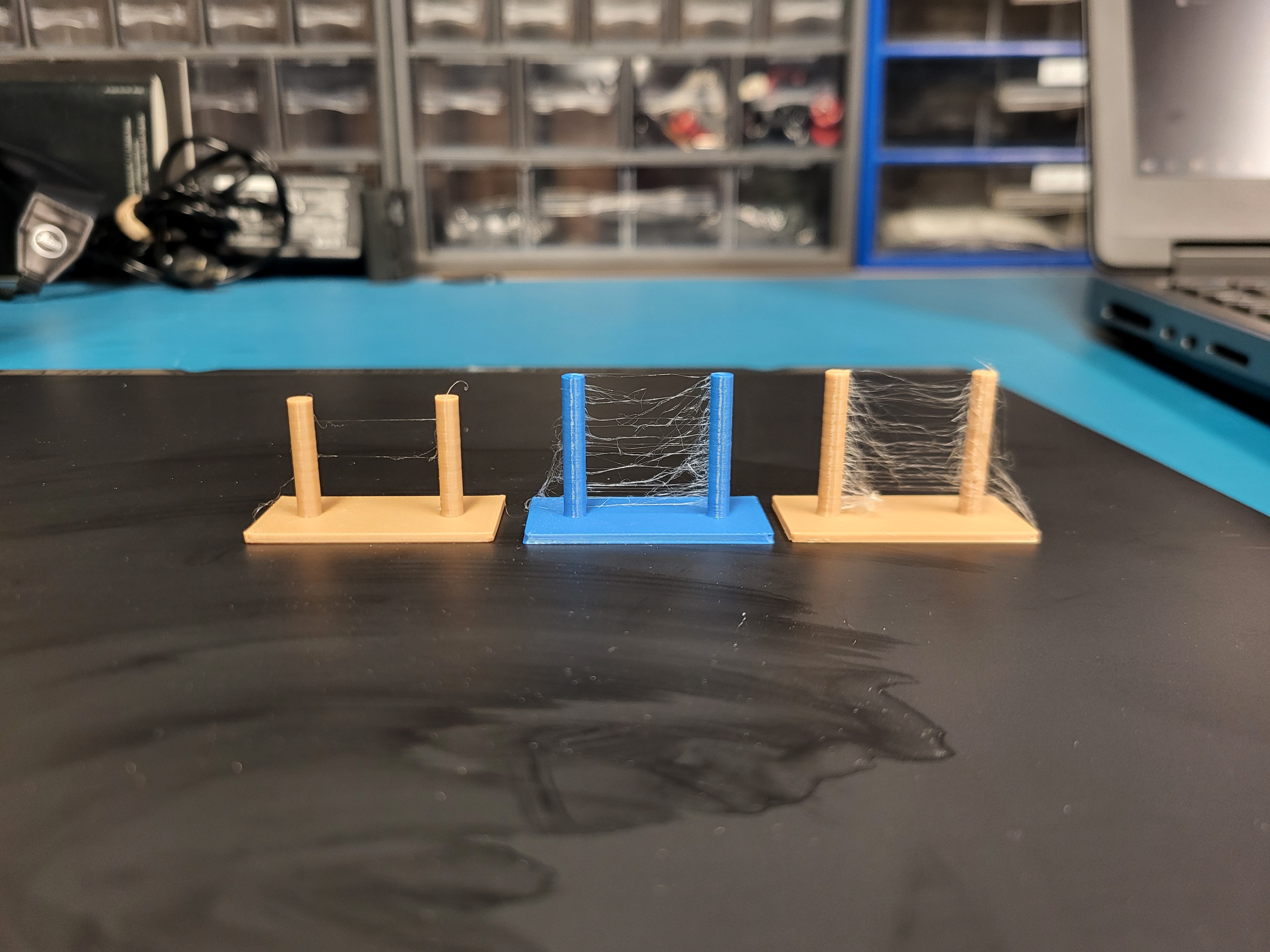
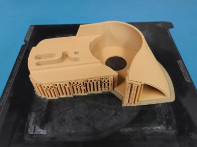
Another important note is to make sure the item you are printing is properly supported. A lot of folks online share this mentality of using as little support material at possible, but this is a silly metric to go by. Like everyting, there is a compromise. It's great to save time by not having to remove support mounts and save money by using less material but the loss in acuracy is hard to swallow in this application. I enabled full support for this print. I find that making the support material originate from the plate instead of the object cuts down on part cleanup time and does not consume much more material, which is a great compromise for me. I could have selected smaller areas to support and used more unsupported overhangs, but I wanted a properly dimensioned part. PLA from microcenter is also only $9 so whose counting pennies at that point!
The first print finished Sunday night and although the printer errored about three quarters of the way thru, it verified which parts of the geometry worked and which did not. I had to alter the model just a little bit to allow for the proper clearance for physical assembly.
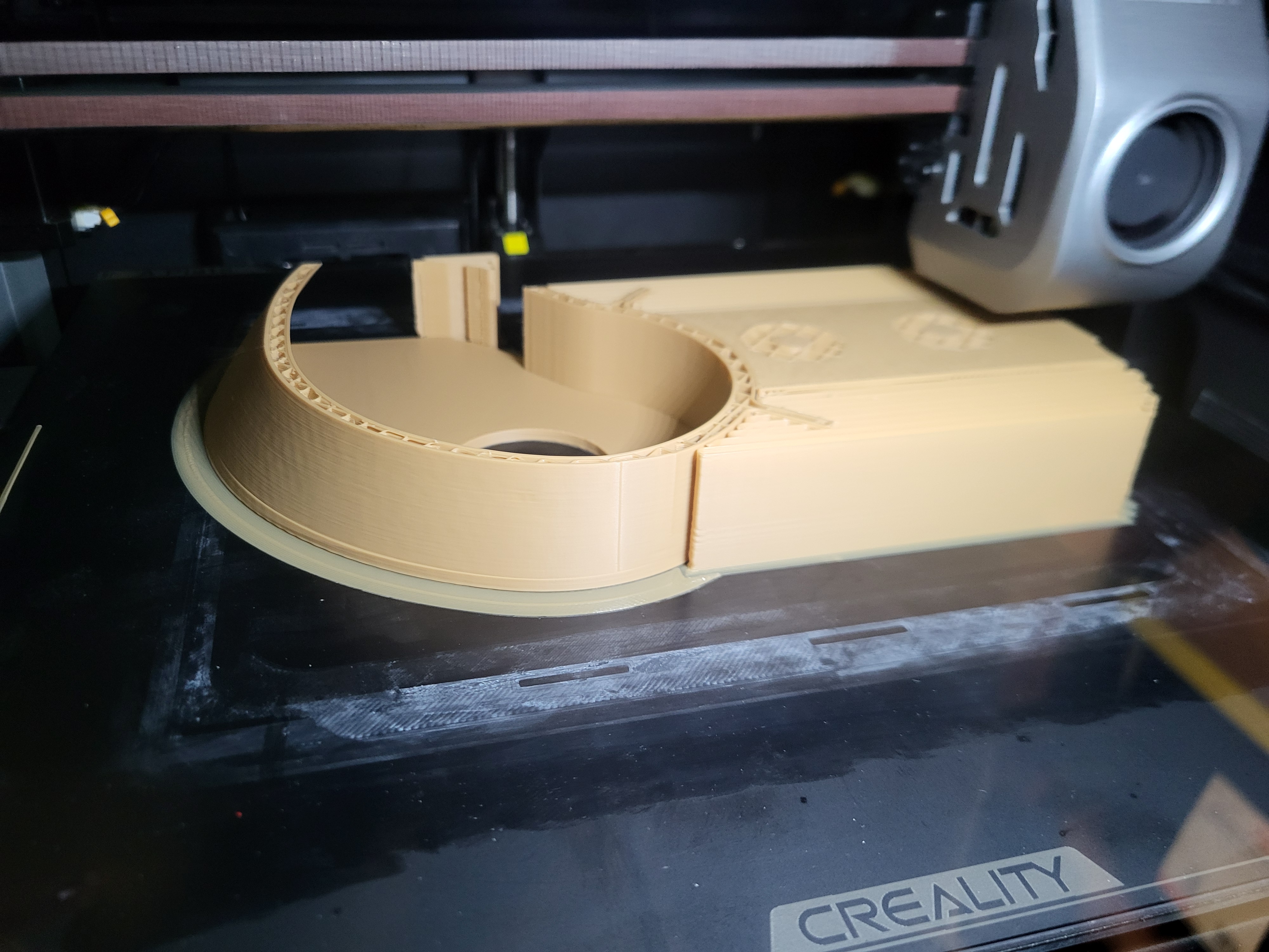
The second print came out really nice and fit without any issue. This print took just over four hours to complete.
The original part was made from cast aluminum, so that is ideally what it should be produced from. PLA is an incredibly convienant material to use for modeling, but it is not at all UV resistant and while It can take some abrasion, it suffers from the same layer adhesion limitation as all FDM prints. A duplicated cast metal is best. The model will now be scaled up to account for the 3/32” shrinkage of aluminum per foot, so that the cast part will be the correct size before final machining. All of the holes that are machined will be solid, so the fit can be made exact.

The saw has a 105cc 4.5hp @ 4500rpm west bend engine and is/was very impressive for its day and age. I had the opportunity to run and cut with Deans chainsaw and although heavy, it has a lot of torque to power thru the cut without slowing down. I thought you would like to see the 3D model and the printed result.
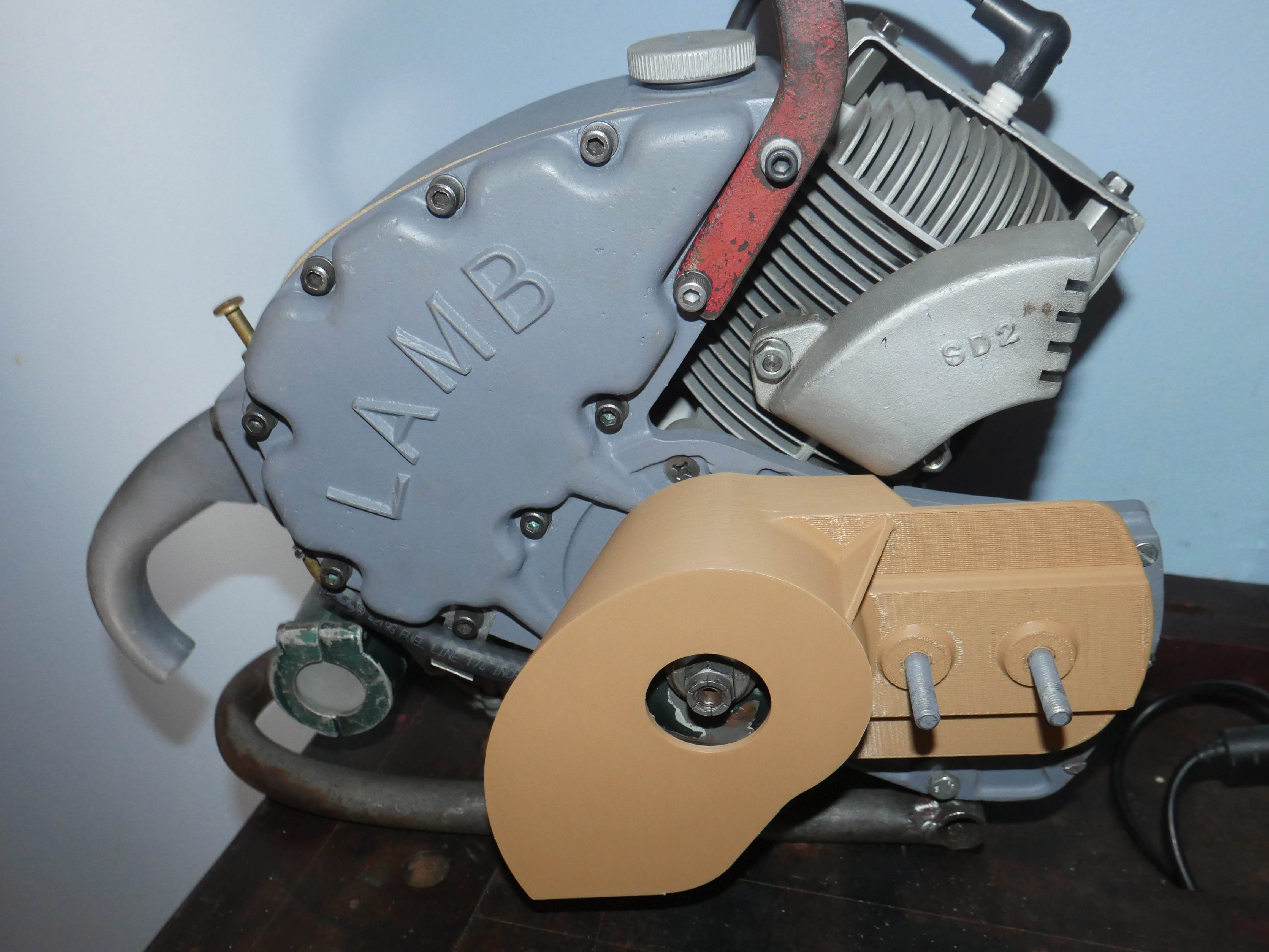
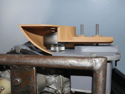
But wait, there's more! Look at that bottom side view. Snug like a bug in a rug!

Thanks for Reading!
Want more? Here's a behind the scenes look at my workspace and some of the images that did not make the cut to be included in the write-up: